SELF-HEALING MATERIALS FOR
RF
ANTENNA AND THEIR APPLICATION IN MININGSELF-HEALING MATERIAUX POUR ANTENNE
RF
ET LEUR APPLICATION DANS L'EXPLOITATION MINIEREMÉMOIRE PRÉSENTÉ
COMME EXIGENCE PARTIELLE DE LA MAÎTRISE EN INGÉNIERIE
PAR
EHSAN MAJIDI AHI
Mise en garde
La bibliothèque du Cégep de l’Témiscamingue et de l’Université du Québec en Abitibi-Témiscamingue a obtenu l’autorisation de l’auteur de ce document afin de diffuser, dans un but non lucratif, une copie de son œuvre dans Depositum, site d’archives numériques, gratuit et accessible à tous.
L’auteur conserve néanmoins ses droits de propriété intellectuelle, dont son droit d’auteur, sur cette œuvre. Il est donc interdit de reproduire ou de publier en totalité ou en partie ce document sans l’autorisation de l’auteur.
Warning
The library of the Cégep de l’Témiscamingue and the Université du Québec en Abitibi-Témiscamingue obtained the permission of the author to use a copy of this document for non-profit purposes in order to put it in the open archives Depositum, which is free and accessible to all.
The author retains ownership of the copyright on this document. Neither the whole document, nor substantial extracts from it, may be printed or otherwise reproduced without the author's permission.
Erchiqui, and Prof.Mourad Nedil and to my co-advisers Dr. Brahim Aïssa and Dr. Emile Haddad for the ir continuo us support and inputs for the ir patience, and especially for having shared their knowledge. Their guidance helped me in ali the steps of my current research and in writing my MSc thesis.
A special thanks to my beloved family, to my dear wife, my parents, my sister and my baby daughter for supporting me spiritually throughout writing this the sis and the ir assistance in my entire !ife in general.
Œ~l ... 9
Review ... 9
RF Self-Healing ... 9
1.1. Liquid metal ... 10
1.1.1. Liquid metal in micro channels ... 10
1.1.2. Liquid Metal in Wire ... Il 1.1.3. Liquid Metal in Capsules ... 13
1.1.4. Liquid Metal and Single Walled Carbon Nanotube (SWNT) ... 18
1.2. Carbon Nano Tube (CNT) ... 20
1.3. Resettable Fuse ... 28
1.4. Light Self-Healing ... 29
1.5. Software Self-Healing ... 31
1.5.1. Self-Healing by Oscillation principles ... 31
1.5.2. Feedback Loop ... 41
Chapter 2 ... 46
2.1. Them-y behind the self-healing process ... 46
Chapter 3 ... 49
experimental Procedures and results ... 4 9 3.1. Self-Healing Part ... 49
3.1.1. Chemical Elements ... 52
3.1.2. Oven ... 56
3.1.3. Microscope ... 57
3.3.2. An echoie cham ber ... 73 Œ~4 ...
u
Discussion ... 84 4.1. Irradiation Properties ... 85 4.2. Self-Healing ... 97 Chapter 5 ... 113Conclusions and outlook into thefuture ... l13 Future Works ... 114
BLACK ARROWS REPRESENT SOME POSSIBLE WIRELESS LINKS ALLOWING DATA TRANSFER FROM ONE SOLDIER TO ANOTHER. {CHAHAT 2014} ... 2 FIGURE 2: SIMULATED REFLECTION COEFFICIENT OF THE MICROSTRIPPATCHANTENNA. -INFREE
SPACE. --ÜNTHE SKIN-EQUIVALENT ... 3 FIGURE3: REPRESENTATION OF THE BAN SYSTEM IN ... 4 FIGURE 4: (LEFT)MINERS WORKING IN THE UNDERGROUND MINE (RIGHT) MINE GAS SUSPENSION IN
AIR ... 6 FIGURE 5: SYNTHE TIC MATERIALS AND BIOLOGICAL SYSTEMS ROUTES TO HEALING [BLAISZIK 2010] ... 7 FIGURE 6: SCHEMATIC EXAMPLES SELF-HEALING; (A) EXTRINSIC, (B) VASCULAR, (c) lNTRINSIC [BLAISZIK 2010] ... 8 FIGURE 7: (I) ILLUSTRATION OF THE DISCONNECTION AND RECONNECTION OF AN ELECTRONIC
CIRCUIT WITH USING A SELF -HEALING WIRE (SHS) (II) DISCONNECTED CIRCUIT (III) EGAIN CHANNEL TO BE ALIGNED FOR RES TORE ELECTRICAL CONDUCTIVITY ... 12 FIGURE 8: ILLUSTRATION SCHEMA TIC OF SELF-HEALING CIRCUIT PROCESS ... 14 FIGURE 9: A SCHEMA TIC EXAMPLE OF AUTONOMOUS CONDUCTIVITY RESTORATION CONCEPT IN A MICROELECTRONIC DEVI CE. A) LIQUID METAL MICROCAPSULES DISTRIBUTED IN A DIELECTRIC MATERIAL TO SELF-HEALING. B) A CRACK LEADS TO BREAKS THE MICROCAPSULES. C) THE
LIQUID METAL FLOWS FROM THE MICROCAPSULES TO lHE DAMAGE ZONE, AND THEN
RESTORINGA CONDUCTIVEPATHWAY ... 15 FIGURE 10: SELF-HEALING CIRCUIT COMPONENTS, MULTILAYER TEST SPECIMEN, AND EVIDENCE OF TRIGGERED RELEASE. SEM IMAGES OF: A) CA. 200 M M DIAMETER GA-IN-FILLED UF MICROCAPSULES; B) CA. 10 MM DIAMETER GA-lN UF MICROCAPSULE; AND C) CA. 10 MM DIAMETER CAPSULES PATTERNED ON AN AU LINE. D) SCHEMA TIC IMAGE OF A MULTILAYER TEST SPECIMEN CONSISTING OF A GLASS SUBSTRATE WITH A 100 NM TRICK AU LINE PATTERN,
SUPERIMPOSED, SHOWING MICROCAPSULES AND LIQUID METAL lHAT HAS BEEN RELEASED
INTO THE CRACK PLANE OF AHEALED SPECIMEN. [BLAISZIK2011] ... 17
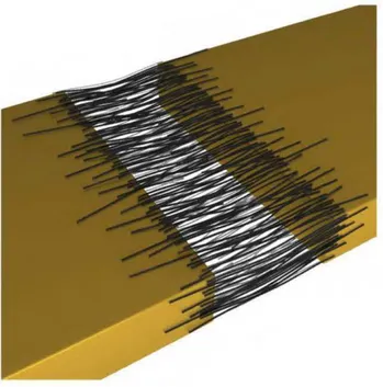
FIGURE 11: (A) TEM IMAGES OF SWNTS. (B) DIMENSIONS OF THE MICRO STRIP PATCHANTENNA (c) TOP-VIEW IMAGE OF THE EPOXY/SWNT -BASED FILAMENTS DEPOSITED BY UV-ASSISTED DIRECT WRITING TECHNOLOGY ON THE SUBSTRATE. (D) TOP-VIEW IMAGE OF THE PATCH ANTENNA PROTOTYPE ... 19
FIGURE 12: SKETCH OF THE STUDIED SAMPLES AND EVALUATION TESTS ... 20
FIGURE 13: (A) BROKEN CAPSULE (B) INSIDE OF MICROCAPSULE AND (c) OUTSIDE OF MICROCAPSULE TAKEN BY SEM MICROSCOPE ... 22
FIGURE 14: (A)MICROGRAPHS OF A CRACK IN ECNT CO A TING WITHOUT MICROCAPSULES (B) AFTER 24 H ( C) IN ECNT CO A TING WITH MICROCAPSULES CONTAINING EPA: ECNT AFTER CRACKING (D) AFTER24 H ... 23
FIGURE 15: (A) BEFORE ANY DAMAGE; (B) AFTER DAMAGE, FRACTURE OF GOLD LINE AND THEN RELEASE OF SWCNTS AND/OR GRAPHEME FROM MICROCAPSULES; AND (c) AFTER RESTORATION, "WHERE THE CONDUCTIVE PARTICLES HAVE BRIDGED THE GAP ON THE GOLD LINE ... 25
FIGURE 16: BRIDGING OF CARBON NANOTUBES IN A GAP OF GOLD LINE WITH PREFERENTIAL ORIENTATION DUE TO ELECTRIC FIELD MIGRATION ... 26
FIGURE 17: TEM IMAGES OF DRIED SUSPENSION ON CARBON GRIDS (A)-(c), OPTICAL MICROSCOPY IMAGES OF MICROCAPSULES SUSPENDED IN MINERAL OIL (D}-(F), AND SEM IMAGES OF MICROCAPSULES COATED WITH Au/PD ... 27
FIGURE 18: LIGHT -POWERED HEALING OF A CRACK ... 29
FIGURE 19: VARIOUS STAGES OF LIGHT-POWERED HEALING OF LINEARLY CRACKED PDO 3 FILMS BY SEM MICROSCOPE ... 30
FIGURE 20: SELF-HEALING SYSTEM ... 33
FIGURE 21: THE SELF -HEALING FRAMEWORK FOR RF CIRCUITS ... 34
FIGURE 22: SELF-liEALING ARCHITECTURE IN THE RF AMPLIFIER ... 35
FIGURE 23: SELF-HEALING ALGORITHM ... 36
FIGURE 29: DESIGNED SYSTEM ... 44
FIGURE 30: RECENT TAXONOMY OF PASSIVE SELF-HEALING CONCEPTS.[AISSA2014] ... 47
FIGURE 31: THE SELF-HEALING PROCESS. (I) THE HEALING AGENT, A MONOMER (E.G. THE DCPD) IS PREPARED AND STORED IN MICROCAPSULES. THE MICROCAPSULES AND A CATALYST ARE SPREAD AND EMBEDDED WITHIN THE STRUCTURE (MA TRIX). (II) WHEN A CRACK REACHES A MICROCAPSULE, IT CAUSES THE RUPTURE "WHICH RELEASES THE MONOMER-HEALING AGENT. (III) SELF-HEALING IS REALIZED BY POLYMERIZATION BETWEEN THE MONOMER AND EMBEDDED CATALYST.[AISSA2014] ... 48
FIGURE 32: VACUUM SYSTEM ... 50
FIGURE 33: EPON 828 ... 53
FIGURE 34: liARDENING AGENT (EPI CURE 3046) ... 54
FIGURE 35: MICROCAPSULE LESS THAN 200 MICROMETER DIAMETER ... 55
FIGURE 36: GRUBBS CATALYST UNDER THE MICROSCOPE ... 56
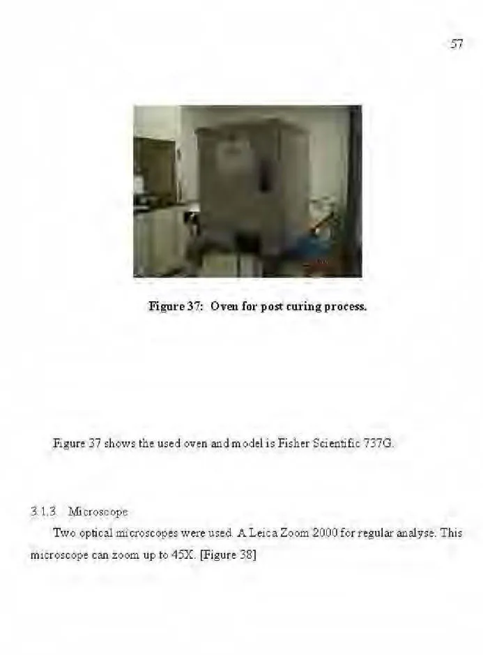
FIGURE 37: ÜVEN FOR POST CURING PROCESS ... 57
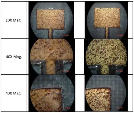
FIGURE 38: LEI CA ZOOM 2000 MICROSCOPE ... 58
FIGURE39: OMAXA35140UMICROSCOPE ... 59
FIGURE 40: SCHEMA TIC PICTURE OF THERMAL SHOCK TEST ... 60
FIGURE 41: THERMAL SHOCK FOR RF ANTENNA ... 60
FIGURE 42: THERMAL SHOCK FOR ANTENNA WITH SELF-HEALING MATERIAL AFTER FIRST LIQUID NITROGEN, (RIGHT) AFTER FIRST OVEN ... 61
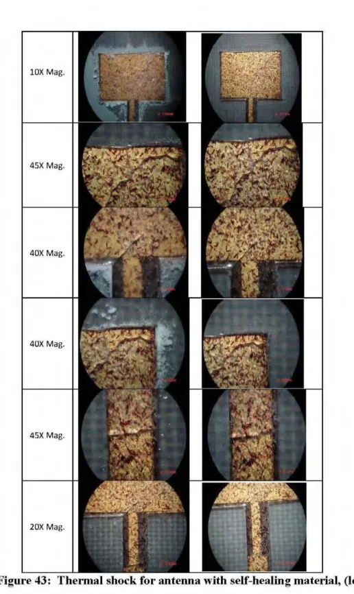
FIGURE 43: THERMAL SHOCK FORANTENNA WITH SELF -HEALING MATERIAL, (LEFT) AFTER SECOND LIQUID NITROGEN, (RIGHT) AFTER SECOND ÜVEN ... 62
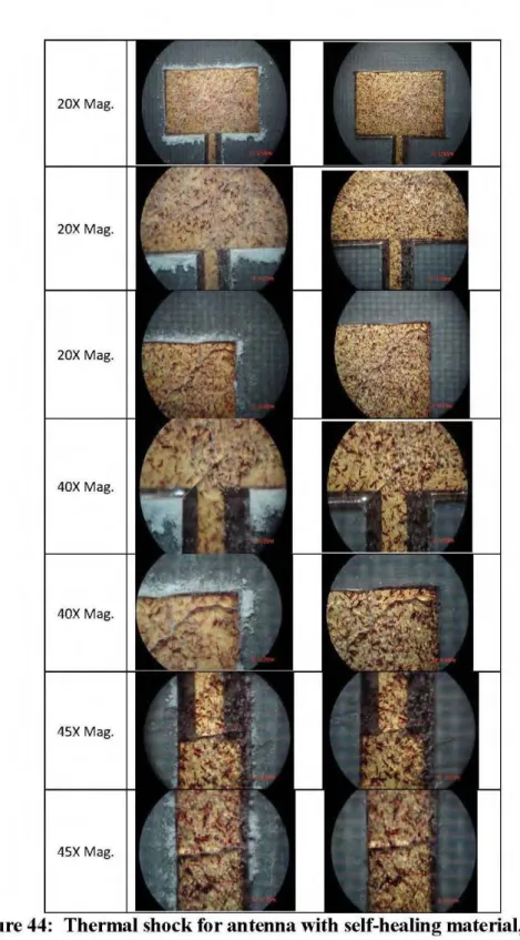
FIGURE 44: THERMAL SHOCK FOR ANTENNA WITH SELF -HEALING MA TERIAL, (LEFT) AFTER THIRD LIQUID NITROGEN, (RIGHT) AFTER THIRD OVEN ... 63
FIGURE 45: THERMAL SHOCK FOR ANTENNA WITH SELF -HEALING MATERIAL PLUS CNTs, (LEFT) AFTER FIRST LIQUID NITROGEN, (RI Gill) AFTER FIRST ÜVEN ... 64
FIGURE 46: THERMAL SHOCK FOR ANTENNA WITH SELF -HEALING MATERIAL PLUS CNTs, (LEFT) AFTER SECOND LIQUID NITROGEN, (RIGHT) AFTER SECOND ÜVEN ... 65
FIGURE 50: MEASURED S-PARAMETERS FOR ANTENNA 1 BY VN ... 70
FIGURE 51: MEASURED S-PARAMETERS FOR ANTENNA 2 BY VNA ... 71
FIGURE 52: RADIATION PATTERN BY ANECHOIC CHAMBER FOR ANTENNA 1 ... 73
FIGURE 53: RADIATION PATTERN FOR ANTENNA 1 WITH SELF-HEALING MATERIAL IN (f DEGREE(LEFT) AND 90" DEGREE(RIGHT) ... 74
FIGURE 54: RADIATION PATTERN FOR ANTENNA 1 WITH SELF -HEALING MATERIAL AFTER THERMAL SHOCK ... 75
FIGURE 55: RADIATION PATTERN FORANTENNA 2 WITH ONLYRESIN ... 76
FIGURE 56: RADIATION PATTERN FOR CLEANED (FROM RESIN) ANTENNA 2 ... 77
FIGURE 57: RADIATION PATTERN FOR ANTENNA 2 WITH SELF -HEALING MATERIAL PLUS CNT ... 78
FIGURE 58: RADIATION PATTERN FOR ANTENNA 2 WITH SELF -HEALING MATERIAL PLUS CNT AFTER THERMAL SHOCK ... 79
FIGURE 59: RADIATION PATTERN FOR ANTENNA 2 WITH SELF-HEALING MATERIAL WITH MICROCAPSULES CONTAINING CNT ... 80
FIGURE 60: RADIATION PATTERN FOR ANTENNA 2 WITH SELF -HEALING MATERIAL ... 81
FIGURE 61: MEASURED S-PARAMETERS FOR ANTENNA ! ... 85
FIGURE 62: MEASURED S-PARAMETERS WITH DIFFERENT MATERIALS FOR ANTENNA 2 ... 86
FIGURE 63: RADIATION PATTERN BY ANECHOIC CHAMBER FOR ANTENNA 1 IN THE 0 DEGREE ... 88
FIGURE 64: ZOOMED OF PEAK AREA OF RADIATION PATTERN BY ANECHOIC CHAMBER FOR ANTENNA 1 IN THE 0 DEGREE ... 89
FIGURE 65: RADIATION PATTERN BY ANECHOIC CHAMBER FOR ANTENNA 1 IN THE 90 DEGREE ... 90
FIGURE 66: ZOOMED OF PEAK AREA OF RADIATION PATTERN BY ANECHOIC CHAMBER FOR ANTENNA 1 IN THE 90 DEGREE ... 91
FIGURE 67: RADIATION PATTERN BY ANECHOIC CHAMBER WITH DIFFERENT MATERIALS FOR ANTENNA 2 IN THE 0 DEGREE ... 92
FIGURE 68: ZOOMED OF PEAK AREA OF RADIATION PATTERN BY ANECHOIC CHAMBER WITH DIFFERENT MATERIALS FOR ANTENNA 2 IN THE 0 DEGREE ... 93
FIGURE 69: RADIATION PATTERN BY ANECHOIC CHAMBER WITH DIFFERENT MATERIALS FOR ANTENNA 2 IN THE 90 DEGREE ... 95
FIGURE 73: WELL DISTRIBUTED CATALYST IN THE RESIN BAS(10X) ... 100
FIGURE 74: MANY UNBROKENMICROCAPSULES IN 10X ... 101
FIGURE 75: BROKENMICROCAPSULES IN THE PATH OF CRACK (20X) ... 102
FIGURE 76: MORE MAGNIFIED BROKENMICROCAPSULES IN THE PA TH OF CRACK (40X, 80X) ... 103
FIGURE 77: ZOOMED SELECTED DAMAGED AREA OF ANTENNA WITH SELF-HEALING PLUS CNTS IN 4X ... 104
FIGURE 78: SURFACE OF DAMAGED ZONE IN 10X ... 105
FIGURE 79: SURFACEOFDAMAGEDZONEIN20X ... 106
FIGURE 80: DIFFERENT FOCUS POINTS IN20X ... 107
FIGURE 81: TWO POSITIONS IN ANECHOIC CHAMBER TEST ... 109
FIGURE 82: MONTHLY EFFECTIVE MASS OF ÜBJECTS IN EARTH ÜRBIT BY REGION (OFFICIALLY CATALOGUED BY THE U.S. SPACE SURVEILLANCE NETWORK. DIVIDED INTO ORBITAL ALTITUDE REGIONS, "EFFECTIVE MASS" ACCOUNTS FOR lHE FRACTION OF ITS ORBIT THAT AN OBJECT MAY SPEND IN THE DIFFERENT REGIONS) ... 122
FIGURE 83: (A) SCHEMA TIC OF THE OPTICAL FIBER (B) LIGHT PHENOMENA IN THE FBG SENSOR. [AISSA 2014] ... 124
TABLE 1: REASONING FOR SELF-HEALING ELECTRONICS [FREI 2013] ... 9
TABLE 2: SUMMARY OF TESTED COMPOSITIONS (DETA CONCENTRATION IN ALL CASES WAS 12.4 WT% ), AND AVERAGE INITIAL ELECTRICAL RESISTANCE VALUES (RO) ... 21
TABLE 3: EXAMPLES OF THE SOFTWARE RF SELF-HEALING METHODS (FEEDBACK LOOP AND EDNA ARCHITECTURE) ... 40
TABLE 4: SUMMARY OF FEEDBACK LOOP SELF-HEALING BASED ON HUSIKAMP STUDY ... 45
TABLE 5: SELF-HEALINGPREPARATION ... 51
TABLE 6: SELF-HEALING ELEMENTS ... 52
TABLE 7: EPONSPECIFICATIONS ... 53
TABLE 8: HARDENING AGENT SPECIFICATIONS ... 54
TABLE 9: SUMMARYOFRADIATIONPATTERNINFORMATIONFORANTENNA ! ... 82
TABLE 10: SUMMARY OF RADIATION PATTERN INFORMATION FOR ANTENNA 2 ... 83
TABLE 11: MEASURED S-PARAMETERS BY VNA AND CALCULATED INFORMATION FOR ANTENNA 1 ... 86
TABLE 12: MEASURED S-PARAMETERS BY VNA AND CALCULATED INFORMATION FOR ANTENNA 2 ... 87
TABLE 13: RADIATIONPATTERNDESCRIPTIONFORANTENNA ! ... 90
TABLE 14: RADIATION PATTERN DESCRIPTION IN DIFFERENT DIRECTION FOR ANTENNA 1 ... 92
TABLE 15: RADIATIONPATTERNDESCRIPTIONFORANTENNA2 ... 94
TABLE 16: RADIATION PATTERN DESCRIPTION IN DIFFERENT DIRECTION FOR ANTENNA 2 ... 97
TABLE 17: COMPARISON OF IRRADIATION PROPERTIES IN THE FIRST POSITION OF ANECHOIC CHAMBER TEST (0" POSITION) ... 108
TABLE 18: COMPARISON OF IRRADIATION PROPERTIES IN THE SECOND POSITION OF ANECHOIC CHAMBER TEST (90" POSITION) ... 110
TABLE 19: COMPARISON OF IRRADIATION PROPERTIES IN THE FIRST POSITION OF ANECHOIC CHAMBER TEST (0" POSITION) AFTER THE THERMAL SHOCK ... 111
Certains systèmes de télécommunication (BAN) ont été proposés pour surveiller les accidents, l'emplacement des mines et l'existence de gaz toxiques dans les galeries des mines. Les BAN sont des systèmes de communication sans fil qui permettent la communication entre les dispositifs électroniques portables et implantés sur le corps humain. En raison de défaillances mécaniques et électriques des opérations de télécommunication dans l'environnement minier, ainsi que de la difficulté, du coût et du temps nécessaire à la réparation ; L'utilisation de matériel Self-Healing pour les systèmes de télécommunications devient importante. Le matériau Self-Healing peut les réparer avec ou sans influence externe. L'idée actuelle pour le travail de cette maîtrise à partir de mes recherches récentes sur les composites Self-Healing pour les applications spatiales. Pour éliminer les dommages possibles et également pour la surveillance de la santé des systèmes électroniques, une nouvelle génération de matériel intelligent pourrait être une alternative appropriée.
Il existe de nombreuses méthodes pour organiser des matériaux Self-Healing qm comprennent des microcapsules, des Ionomères, des Céramiques, etc., qui sont actuellement utilisés. Dans un premier temps, l'effet du matériau Self-Healing sur les propriétés électromagnétiques d'une fréquence radio(RF) est évalué. Deuxièmement, la capacité de Self-Healing pour protéger l'antenne est atteinte expérimentalement.
Sorne telecommunication systems (Body area networks, BANs) were proposed to monitor accidents, miner location and the existence of toxic gases in the mines galleries. BANs are wireless communication systems that enable communications between wearable and implanted electronic deviees on the human body. Due to mechanical and electrical failures of telecommunications operations in the mines environment, and also to the difficulty, cost and time needed for repairing; using self-healing material for telecommunications systems become important. Self-self-healing material can repair them either with or without external influence.
The present idea for this Master's work came from my recent research on self-healing composites for space applications. For eliminating the possible damage and also for health monitoring of electronic systems, new generation of smart material could be a suitable technological alternative. There are numerous methods for organising self-healing materials that include microcapsules, ionomers, cerarnics, etc., which are currently used. In the first step, the effect of self-healing material on the electromagnetic properties of a radio frequency antenna is evaluated.
Second, the capability of self-healing to protect the RF antenna is experimentally achieved.
Chemical vapour deposition (CVD)
Diethylenetriamine (DEI A)
Deviee under test (DUT)
Dichlorobenzene (DCB)
Electrically conductive epoxies (ECAs)
EPA ( ethyl phenyl acetate)
Electrochemical impedance spectroscopy (EIS)
GPS (Global positioning System)
Law noise amplifier (LNA).
Multivariate adaptive regressiOn splines (MARS)
Polymerie urea-formaldehyde (UF
Polymer poly (3-hexylthiophene-2, 5-diyl) (P3HT)
Polymerie Positive T ernperature Coefficient (PPTC)
Power amplifier's (PA)
Power management unit (PMU)
Radio Frequency (RF)
Radio Frequency Identification (RFID)
Self-healing wire (SHS)
Scanning electron microscope (SEM)
Single Walled Carbon Nanotube (SWNT)
System-On-Package (SOP)
System-In-Package (SIP)
System-On-Chip (SOC)
Transmission electron microscope (TE11)
Ultraviolet (UV)
Vector network analyzer (VNA)
INTRODUCTION
Recently, underground wireless communication has become one of the mam research areas in the telecommunications field.
Underground environments like mmes are challenging for wireless communication mainly because of the high path Joss and also dynamic channel conditions. However, many research studies have focused on the implementation of wireless communication systems in underground environments to increase the safety of the workers. In fact, underground mines are subjected to many fatal events. In addition to the accident occurring in mines, other hazardous elements like toxic gases such as carbon monoxide (CO), flammable gases like methane (CH4), fires, and insufficient oxygen concentration could be appeared. Thus, there is necessity to develop and improve advanced and updated technologies for underground safety of miners, especially to the sensing process and monitoring. [El Azhari 2015]
Using of wireless body area network (WBAN) is one way for the monitoring of min ers in underground environment. WBAN is a kind of wearable sens ors located on, off, or in the body. Also, they can benefit civilian parts such as healthcare, persona! entertainment, sports training, and emergency services. For exarnple, in hospitals, clinics, and public transportation system, there is a need to re lay personalized data to and from individuals, in crowds, where the high frequency and highly directive bearns from small millimeter-wave antennas will reduce interference between users and other communication system. Figure 1 show a scenario of soldier-to-soldier communications for a battlefield operation where co-located soldiers are wirelessly networked to allow
l ligh -speed oammurti cat/Qrrs witltin a <!isatt ànged utl:ratt warfa:r~ envirortrrtent [Figur e
1].
M0r eover, f or eaoh sofdier, there is an advanced i êchnology which improves sittiati onâi awa:r·ertess, iéthâii ty and sürvivabili ty such as GPS (Global p0siti onmg System), hel met m ounte d display, RADAR bull et detect~r. etc. [C halrt2Q14J
Figure l:
Soldier-tQ--siJldier C/Jln!lllllliclliiotss fort:l)vert htliJÙffield opemtions. 11ze hkv:k arrows represent some possi.hk wirekss link-s ((l/nwing àrtta t,ransfe" from one sokJierto
tozother.[Ciudutt 2014]
Wh en WB ANs is plaeed dose to the: hum an body, wea:rable antennas need t o be
designed in, su ch a way to operatedn a ·robust mar)ner t 0· minimize the body effect on the antertna: performance. In fa ct, Patch at\tennas are one of the· best Xlptiorts for off~
addition, their radiation at broadside allows maximizing radiations at the opposite side ofthe human body while reducing radiation towards the body. [Chahat 2014]
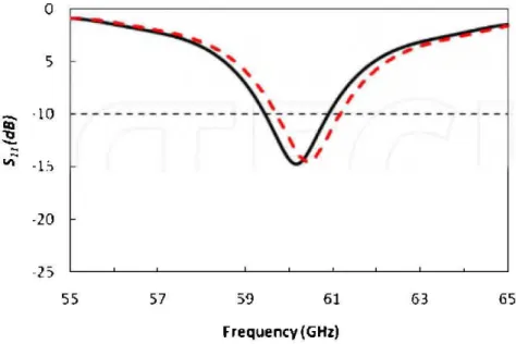
Wearable antennas which have to be integrated with the transceiver need to be as compact as possible. They have to be efficient with minimal power absorption inside the human body that behaves as a highly lossy dispersive dielectric media. In addition, they have to be light weight and, in sorne particular cases, conformable to the human body shape. Recently, researchers are working on the influences of human body on irradiation properties of antenna. Chahat has demonstrated that the reflection coefficient is very slightly affected by the human body, and the radiation pattern remained stable atthe opposite side of the human body as well [Figure 2]. These results have shown that micro strip patch antennas are only slightly sensitive to the human body proximity at 60 GHz. [Chahat 2014]
0 5 ëii' ·10 "l:l
-
~ vi ·b ·20 L> 55 57 59 61 ()3 65 Frequency (GHz)Figure 2: Simulated reflection coefficient of the microstrip patch antenna.- In free space. - - On the skin-equivalent
off-~ddyw~.,.b~ jll\leru~
tlesign
~optimizatio!l, WBAN
body chol)rœl ·modelit)g,
~
!lllàly.;is<oEO\ê
eff~~tsofliWlljU\bôdyonWireless pnf6mûlnée.
[G~2012]
Undet;ground ·mining is one of the most dangerous and l\â7;,tdous erovùotunent
However, for minirog induslly, safetyis undoubtedlythe moslimp:n'lont factor.
Fig~3
dis~so
a.$chemàtic 0fW:BI\N todurologyin
tk
mine. gallery
Figure.J :
Rq>resenlationofihe BAN
S}'liemin
There is permanent! y potential of accident events in the underground mines, and the se accidents le ad to fatal injuries, death of min ers, and hu ge economie !osses for the mining sector. For example, there were 300 coal mine explosions reported with 1037 deaths and over 600 injuries of coal mine workers between the period ofl981 and 2007 in the South African underground mines. There is a report in 1994, which presents rates for mining occupational injuries (per 10000 full-time workers) of 11:8 for disorder associated with repeated trauma, 6:6 for dust diseases of lungs, 3:0 for skin diseases and disorders, 1:8 for disorders due to physical agents, 1:2 for respiratory conditions due to toxic agents, and 1:4 for ali other occupational diseases. To avoid the great Joss lives ofworkers, safety is as mentioned earlier an important factor in the underground mining environment. The automated real-time rem ote monitoring system is established to monitor the gas levels in three different areas: entrance, stop, and stair regions in the underground mine. Rem ote monitoring refers to the access and monitoring of a deviee (in this case gas levels) from a distance location. [Raheem 2012]
Toxic gases are extremely prevalent in the underground mines and they cannot be easily detected by human senses. One of the solutions for monitoring of toxic gas in the mines is RF technology. Radio Frequency Identification (RFID) tag is used to monitor the toxic gas location and transmit signais to the connected sens ors to read the gas levels at a specified time and store them via the gateway to the mine server.
This technology is suitable to observe even the criticallevel; and alerts the mine safety officers on the critical situations in the underground mine regions. Then the mine managers should have communicating with the miners about the actions to take. Figures 4 shows photography of miners working in an underground mine and, a mine with a cloud of gas suspended in the air, respectively. [Raheem 20 12]
*ult
ôfti~tlll~or ilèbondin&, oolh
Withiltcondlltcliv~ patli~ai"'a>ii:lol mte><orw.o:ts
lea_d'·to.liin•~
of hfetim.: of 01\'elec.tronic·
device , Moteover, mecMnicàl âftec-ilitlœ:
~!'&·~mt p;ûomoat>;~of !itbilll1t-ion. b_atflhies ile th, iul!>gra'red cireuits: Jn t he
IJ.a.\le~Ss
rep;tition oflithiàtîo!landdelitlri_atiot) of
elec.lro.d~lud
1o'
pa
!til: le
frac\ute
atiâ
electricai
isoiatiot1,
àtdfinai!ytesuîrinj;
in ac tîeçteaœ i nbamtyc.aJ?I"'ity,
Actuai!Y,
ll'ot
lifdîme of el\)ç f!Olûc n:oatm<ls
oy
res_toring
:of
autollOlllQ\IS'
cOl\dUI<tiVity
throutll
the
Jl\~ase ôf•coi<du~~noati>riàls 'from 'l'llibedded'eaps!lks c&l
1;e
·exle~élWithôut
'"'!1llril)g
">!lydisassetnb
ly.anrJ.tepE~it of®m~edcdl't\)t>ll81lls. [O.dom 20 12]
&$itlÎlly,
wll8n a
1\oal~ria!
1s
lll'<lo< stress,
the
adects
likll
cta!llli;
ôr voiil:>
~~lopla·durillg
the
life
tm'oi< jl1ii le~to
ilSflrilutec
GO!ISeq~ntl:,ç i t's re):Qirii~g11èc.essities Mman inb!lventiott lnspite.d'
b.ytl\e
na!1l1~oro'
biolog~-science .. n..tènal
"'îentlsls:came out with a solulion
~ill8re l~:rtJare.rialcan 1~piirîlself.lndee.d, eitl<er
mh111,nan or orum;ù ôody, v.dilm.an
ÎI).J"'Y~Pr'-',..,.;, bo.ély
staJ1s
to
tepiir•ilsell'Q
y
wl~êllis
o.n.d:''.S'elr.BealllJt'
ot''S'elf'ltef"Îrin('
~ê$S T~J
..
~t)g•Cal\ b~
aulollOln'Îo
ot~·t~yi>$isl»dli4
ht-al,
ligl\for-eli>~likcal sig)lal'.A consi&wle pointis
:u~wMn ~d-.fètllil\#
'l'll~tsWtS
1U
Jl'Ol"'~•le.,. tl\è hbl~.pro.ce'l! Wilfstarl'
inl;,~ntly.'Tl\1;"'Jl'.
-l"
""'"""'l"''
.
...,,..,._
I.:U..I ._!\lll!ol
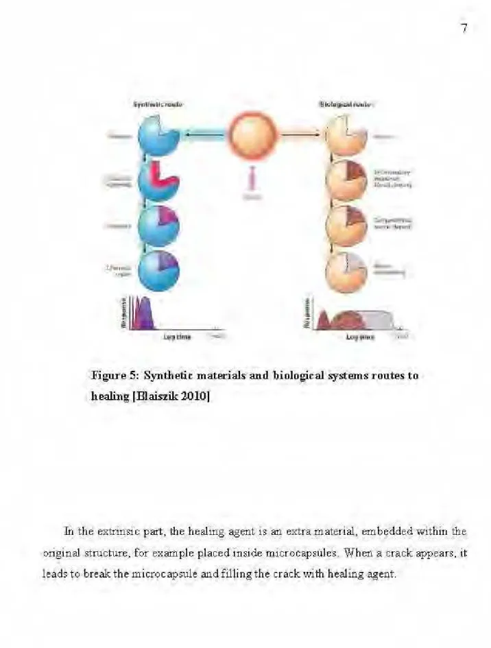
Figure 5: Synthetic m àterials and biolo!:Îcal systems routes to healing (.Blaiszik 2010)
In
the extrinsic part, the healing agent is an extra !llat.erial, embedded within the original structure, for ex ample placed inside microcapstdes . Wh en a crack appears, it Jeads t.o break the microcapsule and filling the crack with healing agent .C: !Mt'IT•
,--- - ----:= =--=-·
Figure 6: Scbematk exam·ples s.elf-heali11.g; '(a) E:.."trinsic,
(b)
Vascula!'.;
(c)
Intrin sic [Blaiszil{.2010)
Il) the caseofintrinsic self-healing prq.ces·s, lliematerials (e.g_ polymer) will repair
themse~ves 'llnder certain cono!lition., like· mechanical stress or temperature.
[Franc es cotti 2012]
The gôal ôf stûdy·t s'the protection of RF ântenna circl\t ts and RFï nstrumênts in general that ar·e· operating in. the ündergrc;>Und mine: environment, by self-healing material film. Also, to increase their lifet:ime, resin ep<DXy' and micro capsules are added to mixtur.e. Moreover,:c.arbon nrurorubes (CNrs) w:ereadded to intprove them:ethanical pr<>perties, and in sorne extend the electricall?rqperties. as weiL
S~at~
of Art
T0 the best ofourknowleqge, this.is firs.t application ofself-healing f!li' teri'al f:Ç>r a
CHAPTER 1
REVIEW
RF SELF-HEALING
Recently, self-healing for RF antennas and circuits attracted increasing attention. There is potential for circuits to have varions defects and then lead to break. Especially for the miniaturized systems, for economical reasons and for saving the time, healing phenomena can be considered. Scientists are working on different kind of healing technologies for multiples purposes. Table 1 shows different kind of self-healing reasoning.
Table 1: Reasoning for self-healing electronics [Frei 2013]
Method Reasoning
Data-restoring algorithm Development of algorithm; laboratory hardware
demonstration
DNA approach Theoretical development awaiting hardware implementation
Healing nana-tubes Nana-tube suspension in capsules demonstrated; healing of
electronic material to be demonstrated
Healing capsules Laboratory demonstrations showing healing of electronic
material
Melting fuse ln active use for seve rai years for production repair and in-use
self-repair
Embryonic Hardware/software at conceptual stage; sorne instances of
hardware validated in a laboratory environ ment Software and formai methods
Technology concept formulated for red un dancy
Sharing of local/global diagnosis
Technology concept formulated information
1.1. Liquid metal
1.1.1. Liquid metal in micro channels
Dickey et al. used liquid metal as microcapsules to self-healing applications. [Dickey 2014]
Liquid metal (Eutectic Gallium Indium, EGain) was injected into the elastomeric micro channels. By cutting the wires with a blade, oxidation allows the liquid metal to remain in the channels and also stay flush when interfaces are made by cutting. With pushing the wire to back, initial shape physically, then polymer self-heals by hydrogen bonding and establish the electrical conductivity again.
Because mercury is a toxic element, another alternative like EGaln which forms a thin oxide layer on its surface, was considered. Participation of oxide interferes with electrochemical measurements, alters the metal fluid dynamic behavior. Dickey has showed that solid oxide "skin" leads to new usages for liquid metals, including self-healing circuits, shape reconfigurable conductors, and stretchable antennas, wires, and interconnects.
Most of the metallic elements are solid at room temperature, but there is another group of metals which are liquid at room temperature, like Mercury, francium, caesium, gallium, and rubidium. Francium is radioactive, caesium and rubidium are both explosives, and mercury is toxic. So, only gallium and its alloys are proper for safe applications.
In the presence of oxygen, gallium surface makes a passivating oxide layer, which provides a physical, chemical, and electrical barrier which cau hinder the metal to be in direct contact with the environment.
Self-healing w1res made by injecting EGaln into microchannels which is composed of self-healing polymer. Another possible way to make self-healing wires is dispersing liquid metal droplets in polymer which is then placed on the conductive traces of gold. After the cutting by blade, the gold breaks, and liquid metal escape from the pol ymer matrix and contacts the resulting gap. Renee, allo ys with the gold material could help to regain electrical conductivity along the gold pathway. [Dickey 20 14]
1.1.2. Liquid Metal in Wire
Palleau has fabricated a w1re of liquid metal which was injected into microchannels composed of self-healing pol ymer [Figure 7]. Cutting by razor leads to oxidation the surface of the liquid metal, and forms a thin oxide film. The film prevents the metal from escaping from the microchannels and also makes it flush with the interface of the channel. [Palleau 2013]
This film also helps the metallic element to adhere to the polymer. EGain was used as liquid metal because of its conductive pathways with high electrical conductivity that benefits from the low melting point (15. 7
°
C) and low viscosity, showing a promising way to create both mechanically and electrically self-healing composite. Metal is able to be shaped via its injection in microchannels, which could be useful for antennas, interconnects, soft electronics, reconfigurable optics, and micro fluidic deviees.withEGaln
+
-(iii)
+
-Figure 7: (i) Illustration ofthe disconnection and reconnection of an electronic circuit with using a self-healing wire (SHS) (ii) Disconnected circuit
(iii) EGaln channel to be aligned for restore electrical conductivity.
Self-healing wires can increase the electronic components lifetime and are also important for the field of stretchable electronics in which components could undergo significant defom1ation.
T11e self-healing wires offer a new solution to self-rewire electronic circuits and are a potential way for reconfiguring micro fluidic channels into more complex shapes
by a razor. On the other hand, coverage of liquid metal as microencapsulated droplets in the polymerie material could lead to a damaged film of gold to self-heal electrically. The mixture of self-healing pol ymer (Reverlink®) structured with microchannels filled with liquid metal (EGain) is a new method to the manufacturing of shape-reconfigurable and electrical self-healing stretchable circuits.
After cutting by razor, with joining the two parts of the self-healing wire, the electrical conductivity restores instantly. Alignment oftwo wires by hand depends on hand-eye coordination. Palleau has succeeded to align the wires with a diameter of 100 Jlm. After alignment, the liquid metal (EGaln) components connect together forming a conductive wire again. [Palleau 2013]
1.1.3. Liquid Metal in Capsules
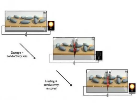
Dadi et al. have used liquid metal as healing capsules having diameter of 10 Jlm. They were coated along the external part of the component with self-healing material. By initiating a crack, the microcapsules are broken and then release the liquid metal into the crack. After filling the crack, electrical flow is established ag ain. [Dadi 20 12] Figure 8 and 9 showing a schematic of this self-healing method as capsules.
"'""'
~""'
condu<tm~
" \ .restored
Figure 8: Illustration schematic of self-healing circuit process.
In another work, Blaiszik has proposed an electrical self-healing method tore store electrical conductivity in a broken circuit automatically.
Release and transfer of liquid metal microcapsules to the area of dan1age are the bases to this self-healing method. Be cause EGaln allo y has relatively high conductivity of 3.40 x 10⁴ S/cm and a melting point around 16 °C , proposed as the healing agent.
Also polymerie urea-fom1aldehyde (UF) was used as shell wall for encapsulation of EGaln. [Blaiszik 20 11]
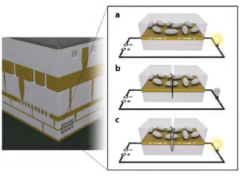
Figure 9: A schematic example of autonomous conductivity restoration concept in a microelectronic deviee. a) Liquid metal microcapsules distributed
in a dielectric material to self-healing. b) A crack leads to breaks the microcapsules. c) The liquid metal Oows from the microcapsules to the
damage zone, and then restoring a conductive pathway.
In fact, electrical conductivity was recovered with low quantity of smaller EGaln microcapsules specifically located at the damage site. With decreasing the microcapsule size or increasing oftheir volume fraction, probability of intersecting and rupturing a capsule with the propagating crack will increase as well. After the propagation of the crack and the rupture a microcapsule, the liquid metal is released and makes an electrically conductive pathway where the electrical conduction
restoration happens with high efficiency. W ith considering the size scales of the circuit damage, optimal conductance restoration may need a variety of capsule sizes. Self-healing procedure and sorne SEM images of system shown in the figure 10.
Figure 10: Self-heating circuit components, multilayer test specimen, and evidence of triggered release. SEM images of: a) ca. 200 p.t rn diameter Ga-In-f:tlled UF microcapsules; b) ca. 10 p.t rn diameter Ga-In UF microcapsule; and c) ca. 10 p.t rn diameter capsules pattemed on an Au tine. d) Schematic image of a multilayer test specimen consisting of a glass substrate with a 100 nm thick Au tine pattern, epoxy dielectric with dispersed Ga-In microcapsules, notched glass top layer, and acrylic bottom layer. Crack damage initiates at the notch root and propagates through the specimen before arresting and debonding at the acrylic interface. e) Cross-sectional SEM image showing the location of the damaged area and subsequent liquid metal release (false color). f) Micro-CT data, with schematic superimposed, showing microcapsules and liquid metal that has been released into the crack plane of a healed specimen. [Blaiszik 2011]
Blaiszik et al. have also demonstrated successful autonomous recovery of electrical conductivity in mechanically damaged circuit. This kind of Self-healing method of circuits will increase the lifetime and reliability of deviees in mechanical environments, and also it is enabling new applications in microelectronics, advanced batteries, and electrical systems. [Blaiszik 20 11]
1.1.4. Liquid Metal and Single Walled Carbon Nanotube (SWNT)
Aissa et al. have designed by the UV assisted direct-writing technology a fluid patch antenna which is operating at the S-band frequency domain, and based on an electrically conductive nanocomposite, that is composed of EGaln and Single Walled Carbon N anotube (S WNT) material. [Ais sa 20 13]
The fabricated fluidic antennas have shown an increase both in their electrical conductivity and reflection coefficient as a function of the integrated quantity of SWNT (results were supported by simulations works ). As mentioned, Ais sa et al. have first utilized a UV -assisted direct-writing technology to design the patch antenna onto a PDMS substrate, followed by injecting and encapsulating the conductive EGaln/SWNT nanocomposition. [figure 11]
20nm
(b) w
Substrate
PDMS
Figure 11: (a) TEMimages ofSWNTs. (b) dimensions ofthe micro strip patch anterma (c) top-view image ofthe epoxy/SWNT-based filaments deposited by UV -assisted direct writing technology on the substrate. ( d)
top-view image of the patch antenna prototype.
On the other hand, they have demonstrated that SWNTs have a direct effect on the long-tem1 stability of the antennas by mechanically bending them more than 12 months.
1.2. Carbon N ano Tube (CN T)
1.2.1. CNT as a Microcapsule
Baileya et al. have used the CNT as microcapsule with epoxy for self-healing purpose. Having an EP A (healing sol vent: ethyl phenyl acetate): CNT core in microcapsules, contribute to electrical conductivity and mechanical properties were restored to be 64% and 81 %, respectively. Figure 12 shows when a crack occurred, the microcapsules are broken and fill the crack path by the healing solvent. Using the electrically conductive epoxies (ECAs) for extemal coatings will contribute to electrically self-healing. [Baileya 20 15]
0 0
°
0 0°
0 o 0 0° -
Microcapsules containing o 0 o o Epocyl and El A Coating is applied to substrate for testin/mmM5005
l
l
l
CNT: \ Hardener:/ 50~m PENElectrochemical Impedance Tenslle loadlng wlth slmultaneous electrlcal
Spectroscopy- verity electrical measurement -% of mechanical and electrical conductivity and barrier restoration restoration
However, the main element that ensures an electrically conductive self-healing is the carbon nanotube material. Because of their excellent electrical conductivity and also high aspect ratio, CNT are an excellent option for regenerating the electrical conductivity. Using the CNTs may increase brittleness and then cracking. They made two self-healing coatings contained microcapsules filled with EP A and either epoxy with CNTs or without CNTs [Table 2]. Therefore, two different methods were used for self-healing evaluation. First, electrochemical impedance spectroscopy (EIS) which is a non-destructive method and, second, test method was a novel in situ electro-tensile test. In fact, EIS was utilized to assess the potential of the CNT and without-CNT microcapsules to bridge and restore cracks.
Table 2: Summary oftested compositions (DETA concentration in all cases was 12.4 wt% ), and average initial electrical resistance values (RO).
Microcapsule Average initial
Pur pose core Coating composition resistance (RO)
composition [MO]
Mechanical and electrical 97.5 wt% ECNT + Microcapsules:
healing EPA:2.5 wt% di eth yi enetria mine( DET A) 0.86±0.12
ECNT 97.5 wt%
ECNT + Microcapsules:
Mechanical healing EPA:2.5 wt% 1.30±0.22
di eth yi enetria mine( DET A) EPON
Control (Eiectrochemical Impedance spectroscopy
100%
-EIS- and in situ electro ECNT + Microcapsules:
tensile loading)-effect of hexylacetate di eth yi enetria mine( DET A) 1.55±0.26 microcapsules on coating (HA)
properties
Control (EIS and in situ No ECNT:
electro tensile loading) microcapsules di eth yi enetria mine( DET A) 0.45±0.23
Control (EIS)-effect of No
conductive capsule microcapsules EPON:
di eth yi enetria mine( DET A)
T11ey used 97.5 wt. % EPA: 2.5 wt. % ECNT for Microcapsule core composition and ECNT
+
Microcapsules: DETA for coating composition and for mechanical and electrical healing.Figure 13 shows a cross-section view of the microcapsule, which it's inside smooth and rough outside. The detailed view of the intemal surface of microcapsule which is in contact with the healing sol vent (EP A: ECNT) is available in Fig. 13b. T11is surface is capable to decrease mass transport of the material through the microcapsule she11. T11en, it leads to relatively better containing healing agent in the microcapsule until
dan1age occurs. In contrast, Fig. 13c shows outside surface ofthe microcapsule which is rough due to agglomeration ofUF Nano particles.
Figure 13: (a) broken capsule (b) inside ofmicrocapsule and (c) outside of microcapsule taken by SEM microscope.
Figures 14a and 14b show the optical micrographs of original and healed cracks of a sample of pure ECNT deposited on substratum where the crack is still present after 24 hours. Also, there are similar results for HA capsules were added into the film. Crack width values are shown in the micrographs.
-24hours...,.
Figure 14: (a)micrographs of a crack in ECNT coating without microcapsules (b) after 24 h (c) in ECNT coating with microcapsules
EIS testing demonstrated that coatings containing microcapsules with an EP A: ECNT or EP A: EPON core lead to improved barrier restoration, and also when microcapsules with an EP A: ECNT core were incorporated into the coating, electrical conductivity and mechanical properties were restored to 64 % and 81 % respectively.
1.2.1. SWNT and Graphene as Microcapsule
Odom used microcapsules including suspensions of polymer-stabilized carbon nanotubes and/or graphene flakes for the conductivity self-healing in fractured gold !ines. Advantage of using the CNT is bridging a gap in go id line with preferential orientation because of electric field migration.
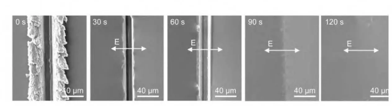
When the sample broken, a crack formed in the go id line, then conductivity will be !ost. Once the carbon nanotubes and/or graphene suspensions from capsule cores released in the same time, conductivity restored instantly. Electronic materials lifetime can be extended with conductivity self-healing via the releasing of conductive materials from embedded capsules, without repairing of damaged components. Autonomie restoration of conductivity of fractured patterned gold !ines by damage triggered release of polymer-stabilized carbon nanotube and/or graphene suspensions is shown in Figure 15.
{Cl)
.
'
Figure
J~:(a)liefOre
any
dllll\age;;j)ü'afler daJI)age,. fràcturé
c~(gold<line!:lnd
ihen zelease. of,SWGNTs•andlurgr'!Phemt! fmm lllilroèap•ule:9;
am'(<)
aller resii>raüm,:where tllllc.onlw:.tire
puticle•
have1>rilgr.d•lliegap on ihe
golcfline.
l':ddiliortilly,.
Mcto.~a~.s ll$-&~te!ISP.tl'"
f.Ql~l)lij[tlf
~1\0ricircllliÛ)& of
eiSt®ni,c ci\c1lit colnJ!-'ll'tlfs whetl
ele.ctric. freld
tn~gl!llioll mvig~~sthe
c.ôibotl
c\OiiOllla1eÛâJsJ,U.Jetel\1i'àJJ)/
1(tij.,
flllcttil~ 2))\\èS'\'tÎthùl "'"'J<goJ!{Jj,lll,,~
Opti:>Sod
(O.~ l;aidot~ CJ'YS~lizalîoll· o~
c!wge transfer s;ùt pr capillaJY-.dtiVan d!>liw;y of llqwB.
Figure 16: bridging of carbon nanotubes in a gap of gold line with preferential orientation due to electric field migration.
This method doesn't need any external intervention or reliance on back-up circuits. These microcapsules compare to the transfer salts and liquid metal eutectics, are more compatible in environments like lithium-ion batteries where anodes are often made with graphitic materials. Also, microcapsules reduce the potential for short circuit. Odom et al. have used the conducting polymer poly (3-hexylthiophene-2, 5-diyl) (P3HT) as an additive to gain stable CNT and/or graphene suspensions in the solvent o-dichlorobenzene (DCB) to improve the efficient release and assembly of carbon nanomaterials from broken microcapsule.
Deposition ofthe solution on gold lines with pre-fabricated 5 ).Un gaps, helped to analyze the electrical behaviour ofthese suspensions. [Figure 17]
Figure 17: TEM images of dried suspension on carbon grids (a)-(c), optical microscopy images ofmicrocapsules suspended in mineral oil (d)-{f),
and SEM images of microcapsules coated with Au/Pd
By applying a 5V potential across the gap, the carbon nanotubes moved to the gap in the gold line preferentially with the direction of the applied electrical field.
They fabricated microcapsules including suspensiOns of graphene and a combination of SWNTs and graphene. In fact, both suspensions of SWNT and graphene are being able to efficient self-healing. Averagely, complete conductivity self-healing happened in 25% of samples and also partial self-healing occurred in 50% of samples, and only 25% with no healing response.
1.3. Resettable Fuse
This kind of fuses utilize a thermoplastic conductive element known as a Polymerie Positive Temperature Coefficient (PPTC)thermistorthat impedes the circuit during an over current condition (by increasing deviee resistance). The PPTC thermistor is self-resetting in that when current is removed, the deviee will cool and revert to low resistance. These deviees are often used in aerospace/nuclear applications where replacement is difficult, or on a computer motherboard so that a shorted mouse or keyboard does not cause motherboard damage. [Kishore 2014]
U
lighl Seif-Hea/ing
Kong et al. have prop>sed a light-p>v,.red
self-heal~electrical conpuctor for
""arable deviees (e.g., the electronic skirl, sensitive
to·mechanical motion). Compare
toother self.healing methods, his method
with
1\elping the green light
~ati.oncan
heal the darnaged electrical conductor·much faster (Jess !han 3
min).[Kong 20141
Figure 18 shows howctacks be healedby light. The.yhave used an ep>xybased
amorphpus p>l}tller, p>ly(dispnse orange) 3 (PD03) as azobenzene mabnial.
Kang et al. have also used a photochromic soft material or photofluidic diffusible polymerie backing layer (azobenzene material), and this material was found to be able to be directionally diffused along the light polarization.
Also, regardless of crack propagation direction, light incident angles, and the number of cracks with respect to light polarization, this material diffusion directionality enables an efficient healing method. [Figure 19]
Figure 19: Varions stages oflight-powered healing oflinearly cracked PDO 3 tums by SEM microscope.
By light healing method, silver nanowires can be deposited as conducting material on the top layer of the photochromic soft material.
Also, healing method can be repeated for 3 times. Directional photofluidic diffusion of AgNW (Silver nanowire) mesh/azobenzene material, distributes the basic concept of light-powered healing for rem ote restoration of multiple irregular cracks on
curvilinear substrate (for wearable deviees applications). Light-powered healing needs improvement in the repeatability and this is crucial for realistic wearable electronic deviees applications.
1.5. Software Se/fHealing
1.5.1. Self-Healing by Oscillation principles
During the last decade, System-On-Chip (SOC) method has been performed to integrate digital, analog and RF circuits on a single chip to miniaturize wireless communication systems. In addition, SOC method is a promising solution for the miniaturization of RF systems, but it is restricted by Low-Q passives and substrate coupling. Other approaches for miniaturization are System-On-Package (SOP) and System-In-Package (SIP) approaches which have shown potential to better integration of digital, analog and RF performances. Even though, these related technological advances have been reduced many problems associated with manufacturing complex integrated RF systems.
The manufacturing cost of RF systems is still a major concern for industry because ofhigh test cost and yield issues of RF circuits.
Reducing the transistors size willlead to:
Lower power consumption
- Higher integration of systems on chip
In addition, the power amplifiers will suffer from lower supply voltages and Process-Voltage-Temperature and Environment (PVT-E). A self-healing method can help to repair any differences in the RF-power amplifier caused by PVT-E variations and decrease overhead on the RF-power amplifier system. By performing self-healing, the efficiency of the RF-power amplifier can be increased.
There are severa! methods for acquire the data required for RF self-healing:
- A common method is based on the self-resonance method. In this case, the RF circuit is brought into oscillation and its output signal is investigated. The resulting waveform can then be used as input parameters for the self-healing algorithm.
- Another method is to determine the amplitude of relevant signais and uses these in the self-healing feedback loops. Most amplitude detectors consist of simple circuits and use little space and power. One of the main disadvantages of this method is that the phase and shape of the signal is disappearing, and then smart measurement points and relations should be used to measure the relevant parameters.
It is possible to gain detailed information on the power amplifier's (PA) performance conditions by utilizing expensive measurement equipment. The acquired information from these measurements can then be used to improve the sub-optimum performance of the PA which would lead to decreased design margins, but this is a time consuming and costly. Also the information of input and output signal of the RF-power amplifier is limited.
···---···
' l'hl~
wolkt
11
M!:nkttrr!t
L_.
_ _
- - ---.-1
M
go ri tluri
Omtrol
Figur e
20: Self,healing
~ystemPow~r
.atrtpfifiers
$u.f~rlrPfil
PVT-E ÇP'racess~Volt~e-~Temperature andEnvi'rQlun ent)
~m1
aiion s- w1ri.Gh
are nonn
W!y
slow pr«cess:es; hu:thave high-
itnp.al:t on the:amrtlifier behaviol• ar,J
peif~rmance.Thes'e·
variation:•
caü~ed Îr,r'FilT -JE
f;1J!lbe
rem ove: d by a :self -h êalin,g
s ys.rem[figure·
2JJ]
In a~lf-heal~g
sy:netn,.
atnplÜLerpr·opertîes
we
adj~J>Stedto
t>;mp:en~atearry
PVT-E
cliffefertee~that o'Ccuneil
durlng
pt~:>du.ctipn ·Or·QperatiPn.
whicb:
>l
achieved
by
a$~um»tg
that tll:e runplifi:et
is. diff:ereM friltu the Ideal
~n:e.Reoently, mi niàturi:1;ing,ofthe-RF
syste:l)ls C\3!1 be dot~e. .QySy$!e.m-Oh-ô!\ip
($:OC), S.y~ tem-On-Package(S:O!')
and S.,ste:l)l.Jn:.-Pack~ge(SŒ)
approaches
Tf!
façt:; SQC intygrate th~ digital, anal,og,.~à RF circuits to .a u,nifontLc)iip.
Althoughàl!
o.f the:se
AblûlaSll P,li>p:ised a
ft~)'!Ork·fbrthis
pl'Oblelll. This
fran~eworkiJ·;,;luded k>w
cast
testiJrg me.thodolo.zy for
llJ'
ampiifœr
[Fig1llll
21]
,l!
us~s 10\~ l'ie~sl€)11ll
atid
lly
lo'
il\reglat.l' RF' subslrares
to
an
~rnb~dde<llU'
~sivefiller.
Qscilhtîoli
prif,;i]:ik
\!Sed jo
~wbfe
lest~ot:Tl:F'cfrc.ui!S
without
!lll)reliNrnàl Utfluellces.
'Sè~or.dpîrt•of this f'ialîtovlork•s imteasing tlœ:
R:F'tfrc.uît
yjeld'for
j.aranletricdefect V?ltich
il;,;ludedadîagr.osis slgpritlu:n fori del)tify clal:naged circuits. [Aohllasl\ 20! ! ]
- - - + - - - _ _ . _
'
'
Te.slj!'.g t.f Rf $1Jbsl'i'ii\e'"i
~~~E!Jid-~ RF P.a~iYe filiel'i).
J~•lln~ Ul
li'{F-(\-:livo: Orçûits t'RF .alnplifi'~?i:)
'
'
•• : kQp!j:S~.d! <P T !'~t lnt-lt'tlt.t<r-'
'
.,.
''
.f.
'
'
•
· - - - - + - - - · - - - ~'
'
'
.Sejt;;Healing êfRF" Circtjit~ (embetl.d~d RF c:tt(';\lit~)'RF arn~lf'1et an·J1 M!xer
t
'
'
1"~
tlll.$1!'a\Q ' Yie4:JlmprOv~rr.~·
t
'
'
~liSt ~1tlc ~feçts, ~\iiasJt~!iiL ir~ us~~-~· t®!i<wfujogyba:s~<ioo>oscilllltio!\
)lliÎrol;i~
m
dlmQelll\d~•lilst
(Qtrfl
Wlùcll
i!Sftlf
~tl!lrat~tl1!1i!;SI,sil!))lll!ll!>.
'Tio~;stùnulli$~•~s
to
o$ses~ tl'$ir,J<j>'icl
of' f®c.~s~ \~tiôttl Ol) ~DlJT o:wratJOn. ill
ailèlifibrt,
cOtnplliS!!.ùoll
for
Joss
.qf[;iut
nnfO®at~Ce
d11ê-ioN>tlàt=
•-•:>cwt
''~
atlji!Sti~ ,th); ~allb"raliollltu(ù~og,W'b"'-
l!r ill!'
~ll!!oealit)g 11t:oil~<.ei<tmoal
f.tedl>~d;ellaJiJ>-$""'10Ss th~·JbwtiOi9l 'alfiP.hf~Gf
(JJ{A), lFJ!§lll>l'
~2)
f!O
J;$ TO-!K ® ur>L""F.;'111~, )-NAos~UMe ~ntrare
a
sir.II!SO~sig,roal
fortesfu;g-~dcahh!iilîOll.ill
~~,tire ~~$ÇkMt~rothl:>a )Jha's'~ shi
fj2r
"iûclt
cattbt<
oçcmnpilshe:d.
O~C
cJ®omff-ç'fujloot 1i<e C'ircJli1S.
,A-ç~ually; plfl!se~l~r ,is,I;()M~>:çl>c!
10.umut
.wt
t\U~
t'l!1sof
LJII,~
oy
KF'S~<~
to\:'omPie
t<
tlJP fé.eéll>.ad;; loqp. Fi!111lJ>'23 SllilWl> V01
a~ritht)<
ni
<
-'
ln ,the 'l'@sence.of :<ariatibns, s.èlf..J,.aling of the !JNA attOilted byadjUstiltg
ti,.
LHA
JUilii)t!®>bs fiotn
on•chip p:tv,.,r m~<qgement1llli1(PMJ);vrtlt
is
ùsin): i l..:
es~n~l
nece$sities-forwireless conu:t\;UIÛCatîOn,Jilœ ·on-chip RF·
nû:x~r~.J\.00~low
- --
---+- --1
~b"râti~niT"Iljri.§ léJobs.'
'
'
··-·--·-~--·--·---·--( fiF U h• 0 r Bfim1- . RF l,'CiW-plWl: 0.$\? ;!o!(J {i!\\ll
~
Q
!
L
Flilel't:<~~mr.
.:'11~11AOC
pf
~G·enarotion !.'irttUI S...gnal~'- f
·- ··-··-··-··---·-è(lp : ... _. .. ,__ _ _
:'7':":""" ··•
0 "'1·. '
P.reso:.u:t=:::cG
'
'
.
.
,.S.\~1~~
'
t
.
-! .
5elf.':Mli~~_,lt~l fo~ · Fk11'!:e-O::Ii~'
Tn
W;-çummts~lf-~alin&tt\elhofulog)f,
fàil!ll1!d~l!>.klion-p<tf6m~dby
pre&cllW
o'ô;ilhtticorb~éa
l!i:rting
"'rhiclt
is:
clev!llor-<i!
fC>r Pt;-t hi:g
i?stfJ;>g.
·of
RF
lll)lpllûo.r.
l<tèlefore .•dttectilm of:tiW!Is J;ill
be·
p:ossiblè, B.eoli.use o! éxtsteliCe·
Jnajl}\\ill!\'be~•n
1!>..«!
sig_l)aQJre at:•d LNJ>.
sp,cifk~tior;s:A
bilas!)~ JÙ.l<I!Y'> Jl!Op>'sedfor
fu;;t
tim!1,
yield
itrtJ)!Ovt!tiient utlli1'ing
œ.cill>tion.
J!Dl"'!f?lô$.
lll;additiol~ ~lf-iiéa~
Rf
:OU)JllÎtscM
bp ç.on1l'àlkd
by
~.olibtatiolt(
!\llÙt>g,
kno'b:..
~~o,_
tiœ desjgtt
:of
knQbs must be
1tttlt~!
DU1!'
•s}:!lcifi~alionsb•
~petld!>l:ltof'
othm'
Wlcificatior.s,
thlS .
.no•m
.n
sp>olfJ.Cûtiom
to
be·ccm1!!Jlled ùtdècent!ytO
yièid
tecow>y.
lJ'.iJ;,Ure
241
ko~mlfy; t.alibnooru~otte.ctlolt
J)!OPedüre
can be one-tÙ'ile: orit•retive·. h!sa,
t1œ.
iti>totiw
IJlO.<;~urekads
to
lu)]): yield
recOW};j/'b11t. tin>e
cot)Sil!Xoing.l'jbilaslt
for
tktnD.tlS!lliteo
t11e.
""ifhè.ilt)!:;
10rnU4~
t.Wt>
LNPi~;,
Sielè
liB'!'
ut~
o;.d
erros
RF
LHA, 'Fottlie
f~one. ll'tr~uroing ~~10bs
, d,
fiT
c!<ôi>g~t1lf'bia-~·1;Jlltellt(i
_'bi.,;).ana
-A1so>
.to
,!l~lTI)inl;Il«
Uf.~es&Jl)pit.s·
for
~~alîlîraJiorJ~Orre.kiÎOJl, ca ~~ ~.dic.Jionn-oO!l!Ü
~lot<>dfrolll
Mollt.
C;ulo s:imlll~on n~.tlloil by-Jrt!lltiv.dlià~OJ:Iaptive·
1~tasl<ionsplins (MAltS). Mont;)< Càtla.·sim\!Mnon conducted witb 30U
UIM. 'l'hi$·
nred\cûon
n•od~lliPtMèd ID PJ!'dli:.l
•r(lall
sig>:~"!t!Sl)Stt\ÎSsii:>l\g.ain.aJ:od [.
tiB•
t.otrgltés~ÙD~i
t,em!
(PlilB,
i'IBri(J.
TI~·
,J'ii'éliiettdl\
:intJdel
];O!fonn.d
to,f'md
~tûu;atio)ls~ld j:lf•dicre~gail\.
Tl"'
Abll~'lltrot>tl)o'do1o~)! l~.aeen.Sh!lWJ<d.ollOll'tl'(ibtdc!ea
RF LN
A-fu
1hè
W
fîout-eru3'
~•;•lèlros.lt
l\âs.
be~tt:slrow.:n
tlutJ~h·s:imU!atJo>:lS
tliata. ;,jgrurlctutt
~lal:inf.®V'l'1ltelit dfllre
:RF
&l\pliftèt'c.al\
1>e ob1ail\ed
b,ythis~thodo~y.<l1
~boa~a..
leve! prototype and a chip-level prototype of the self-healing LNA have been demonstrated. Also the performed experiments results were encouraging and it can be concluded that the methodology can be considered as a new solution for the development of future self-healing RF systems. Also, Abilash demonstrated for the first time that RF amplifiers can be tested for their specifications using oscillation principles and yield improvement using oscillations principles for active RF circuits. As shown in the table 8, the novel achievements of Abilash thesis are summarized. Table 3 exhibits the example of the software RF self-healing methods.
Table 3: Examples of the software RF self-healing methods (feedback loop and eDNA architecture).
SH method Innovation and Method
Important points
ln fa ct, eDNA architecture included a distributed array of multiple homogenous processing units cal led electronic cells eDNA architecture and and The duty is to impie ment the eDNA program, which is specified by the programmer. Also eCell conta in a
eDNA Architecture
the eDNA program microprocessor and a 32 bit ALU which is configured by the microprocessor to do a function described by the gene. The DNA is a program written for the eCell microprocessor, which performs self-organizing and self-healing of the eDNA architecture. Ali eCells conta in a copy of this program.[Boesen 2011]
Yield improvement
The proposed methodology is based on oscillation principles in which the Device-Under-Test (DUT) itself generales the utilizing oscillation
output test signature with the help of additional circuitry. ln the proposed methodology, the self-generated test princip les. Self-healing
signature from the DUT is analyzed by using on-chip resources for testing the DUT and control ling its calibration knobs to Feedback loop RF circuits can be
compensate for multi-parameter variations in the DUT's manufacturing process. This methodology does not require the controlled by
calibration/ tuning use of external test stimulus for performing self-healing because the stimulus is self-generated by the RF amplifier, with knob s. the help of additional circuitry and by using oscillation princip les (feedback loop).[Abhilash 2011]
A low power signal waveform sampling
Feedback loop system for self-healing Integra ting the measurement circuits in the sa me chip and use the measured RF-signais in a feedback loop to correct the RF-power amplifiers is performance of the RF-circuit.[Huiskamp 2015]
designed and simulated.
1.5.2. Feedback Loop
Husikamp et al. have proposed a self-healing methodology that integrates the measurement circuits in the same chip with using measured RF signal in feedback loop. [Huiskamp 20 15]
Figure 26: Self-Healing methodology.
In this system, if assuming that the amplifier is different from the ideal amplifier, its duty is compensating for any PVT-E changes that occurred during production or operation. In addition, controllable parameters like biasing voltages, bias currents and
matching networks must be changeable to compensate to PVT-E influences. [Figure 26 & 27]
For the real1ze of · Self-healing compensation
Figure 27: Self-healing algorithm
Simple amplitude Detectors
full ADCs
Basically, for perfom1ing the compensation, amplifier infom1ation is required, so some sensors should be adjusted in design. They could range from simple amplitude detectors to full ADCs. Although, DC sens ors could be applying to measure bias points, but they cannot retum amplifier infonnation.
However, Sampling the RF -wavefonn with an ADC will retum the information, but that is power inefficient. This approach the baseband ADC of the baseband
~
17
'~
J:la~c~:îllJi , l:f@ t;fC{If9;'-..
..,._
~.
. _ _
t
-
•
-
•
-
•
-
• Srtll!PI'"f..;..
H""'""'d
<~m:
.
.
• " ••
.
-.
•
'•
Tli\> '-l
oJik.
•
.
-.
1
.
.
•
.
CJootlt
at
n..;;atl~t•
.
-
•
•-
•
-
~-..
--·-·~·f.-'10~-Actu.Jjy;
il\
tÎie'ltlodmt~çuollio •tl:àllSinittet ·~~tél!L<, ihe.~ignaijs:~~q
bq
àiligilal bas®.3lld
pto<;.~;ssor'<1'1Ml;
modulal~sth!.
dola
<îgnaLAful'yt~·sigl)!l) &OlM'rlta
the
;>Mlog;
do~mj!l)q
'lM
m&dlilabd
da
ta
<î'grtlil' is-'tl)!'n
.c;onv~~dto
.tl~, ~r!h<;quen~y.lFilplle
481
TJs~y,
il;
il)numn~ G)JS!o>lll, 1\~ d~layloop iS-tlo,;lsed
'Wl'il) tl~PA
ft•qutl'lt)'
~nàmares
tl"'
t.liffelèl\tpha"'$10l'~j:li• t1~e
t'êfuV•Int RF-WW'#
fortns-of'lhe
PA.
1\iso,
tiwsam1~àllil '~iiçui1S teturt1-the'.e,q:u.llysj:a~ed.
S$'plos-?V'!t 1l!lé P,riQc!of'lhe
!'"Vift
forn•-
H~nce~tMyc.Ol'Mlttbythe' ADC~tl., <nl!llP&dOm~I!J -~digijal
1!01\lànt
-aildalro,,
11\e·
di?i!Ol·salfipies,cdrr1.ertbytlle DFT to .tbe
~usoids. tl~eoutteni$Ji'Sremcan acquire the RF -signal characteristics by converting the high frequency RF -signal
to DC values. In addition, they can be sampled at low frequencies. Because the ADC
can work at very low speeds, so this saves a lot of energy compared to the Nyquist speed ADC. In the Figure 29, proposed system is shown;
This work .-
---
-1Delay Locked Loop 1 Complex harmonies 1
u-ut ~
1 DFT
,...___~~
Sample and Hold ADC
1
---Figure 29: Designed system.
Huiskamp et al. have designed a low power signal waveform sampling system for self-healing RF -power amplifiers is designed and simulated. Also, the sampling system samples RF-waveforms at equally spaced points across one period ofthe fundamental frequency. Seven samples are needed to define the RF -waveform up to the third harmonie. The information about the RF power amplifier can be retumed and this information can be utilized in a self-healing system. However, table 4 illustrate the comparison oftwo methods. Table 4 shows summary offeedback loop self-healing;
Table 4: Summary of feedback loop self-healing based on Husikamp study
Self-Healing method Comment
Compensation of PVT-E (Process-lntegrating the measurement circuits Voltage-Temperature and
in the sa me chip and use the measured Environ ment) variations which are RF-signais in a feedback loop to correct normally slow processes but has great the performance of the RF-circuit. impact on the behaviour and
performance of an amplifier by self-healing method.