Science Arts & Métiers (SAM)
is an open access repository that collects the work of Arts et Métiers Institute of
Technology researchers and makes it freely available over the web where possible.
This is an author-deposited version published in: https://sam.ensam.eu Handle ID: .http://hdl.handle.net/10985/17209
To cite this version :
Duc Tan VU, Ngac Ky NGUYEN, Eric SEMAIL, Walter LHOMME - Electric Vehicles Driven by 5-phase Open-End Winding Machines Fed by Battery and Supercapacitors - In: IEEE VEHICLE POWER AND PROPULSION CONFERENCE VPPC-2019, Viêt Nam, 2019-10-15 - IEEE VEHICLE POWER AND PROPULSION CONFERENCE (VPPC2019) - 2019
Any correspondence concerning this service should be sent to the repository Administrator : archiveouverte@ensam.eu
Electric Vehicles Driven by
5-phase Open-End Winding Machines
Fed by Battery and Supercapacitors
Duc Tan Vu ductan.vu@ensam.eu
Ngac Ky Nguyen
ngacky.nguyen@ensam.eu eric.semail@ensam.euEric Semail walter.lhomme@univ-lille.frWalter Lhomme Univ. Lille, Arts et Metiers ParisTech, Centrale Lille, HEI, EA 2697 -
L2EP - Laboratoire d’Electrotechnique et d’Electronique de Puissance, F-59000 Lille, France Abstract — This paper presents the modeling and control of an
Electric Vehicle (EV) driven by a 5-phase Permanent Magnet Syn-chronous Machine (PMSM). The machine in an open-end winding configuration is supplied by two isolated 5-leg Voltage Source In-verters (VSIs). The inIn-verters are fed by a Hybrid Energy Storage System (HESS) consisting of a battery and Supercapacitors (SCs). To increase the battery lifetime, the SCs are used to provide the high-power requirement during driving operations. In addition, an Energy Management Strategy (EMS) is proposed to take ad-vantages of this EV architecture. Numerical results are derived to verify workability of the EV system.
Keywords — PMSM, multiphase machine, energy management strategy, open-end winding, supercapacitors, electric vehicle
I. INTRODUCTION
Machines with a high number of phases, i.e. greater than three, have been used in several applications such as ship pro-pulsion, aircraft and traction in recent decades due to their ad-vantages such as low torque pulsation, fault tolerance, and re-duced per phase power rating [1]. The recent design, modeling, and control of multiphase machines are analyzed in [2]. Three-phase open-end winding configurations fed by an inverter and a DC voltage source in the flux-weakening region [3] and in degraded modes [4] have been introduced. The open-end wind-ing topologies supplied by dual inverters and two isolated DC voltage sources with 3-phase machines [5, 6] and with multi-phase machines [7, 8] for automotive applications have been extensively investigated to verify advantages of the architec-ture. Indeed, with given values of DC bus and power, the ma-chine voltages are doubled, and the currents are divided by two. Moreover, in the case of failure of one inverter, the remaining healthy inverter can operate independently, which helps to re-sume quickly the operation of the drive system. In an EV sys-tem, the open-winding structure allows also to use two different DC sources to split the peak power demands that occur in ac-celerations and deac-celerations.
The degradation of battery in EVs has been one of the most challenging problems. In driving operations, the battery life-time is badly affected by peak values of the power demands [9, 10]. Besides other factors affecting the battery aging process, the RMS value of battery current is considered as one of critical criteria having impacts on the battery lifetime [11]. In this con-text, the combination between batteries with the high energy
density and supercapacitors with the high power density is one of promising solutions, tackling the problem of high battery RMS currents [12, 13]. Supercapacitors can be used in acceler-ations and deceleracceler-ations (short-term power demand) while the battery is used for operations at constant speeds. The EVs driven by wye-connected winding 3-phase machines fed by sgle inverter, using batteries and supercapacitors, have been in-vestigated in [14-17].
In this paper, the proposed EV system is comprised of a 5-phase open-end winding machine fed by two independent in-verters with HESS. The drive system is described by the Ener-getic Macroscopic Representation formalism (EMR) [18]. Due to the characteristics of the multiphase machine, a proposed EMS enables to control four power flows within the drive sys-tem. In addition, thanks to the supercapacitors, the battery cur-rent is smoothly regulated, hence, the battery lifetime can be increased. The workability of the architecture is verified by simulation results.
The paper is organized as follows: section II describes the modeling and control of the EV; in section III, an EMS is pro-posed to distribute the power flows of the EV; the simulation results are presented in section IV.
II. MODELING AND CONTROL OF THE ELECTRIC VEHICLE
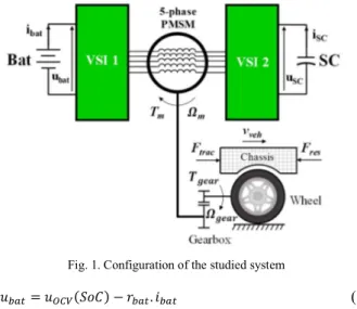
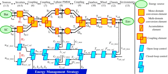
The EV architecture in this study is shown in Fig. 1, con-sisting of a 5-phase PM machine fed by 2 VSIs. The first in-verter, namely VSI 1, is supplied by a Li-ion battery package and the second inverter, namely VSI 2, is connected to SCs. The machine drives a wheel and chassis through a gearbox. In this section, all elements of the studied system will be represented by the EMR formalism. EMR is a functional description of en-ergetic systems for control purpose. The system is split into el-ementary subsystems in interaction [18]. All subsystems of the studied EV are interconnected as in Fig. 2. The models of sub-systems are described in this section. Inversion-based control laws (IBC) [18] are applied to define controllers (in light blue parallelograms) of the EV. In addition, an EMS, controlling the power flows within the drive system as well as to help extend the battery lifetime, is analyzed in section III.
A. Sources and inverters
Energetic models used for the battery and SCs are described in (1-3).
Fig. 1. Configuration of the studied system
𝑢 = 𝑢 (𝑆𝑜𝐶) − 𝑟 . 𝑖 (1)
𝑆𝑜𝐶 = 100%. 1 − ∫ 𝑖 𝑑𝑡 (2)
𝑢 = 𝑢 − ∫ 𝑖 𝑑𝑡 − 𝑟 . 𝑖 (3)
where 𝑢 is the battery voltage; 𝑢 (𝑆𝑜𝐶) is the battery open-circuit voltage (OCV) depending on the state of charge of the battery package (SoC); 𝑟 is the battery equivalent series resistance; 𝑖 and 𝐶 are the battery current and capacity re-spectively; 𝑢 and 𝑢 are the SCs instantaneous voltage and the initial SCs voltage; 𝑟 is the SCs series resistance; 𝑖 and 𝐶 are the SCs current and SCs capacitance respectively.
The average linear models of two 5-leg inverters VSI 1 and VSI 2 are shown in (4-5).
𝑢 = 𝑚 . 𝑢
𝑖 = 𝑚 . 𝑖 ;
𝑢 = 𝑚 . 𝑢
𝑖 = 𝑚 . 𝑖 (4-5)
where 𝑢 and 𝑢 are the 5-dimentional output phase volt-age vectors of VSIs 1 and 2 respectively; 𝑖 and 𝑖 are the 5-dimentional current vectors of VSIs 1 and 2 respectively; 𝑚 and 𝑚 are the duty cycles of VSIs 1 and 2 respectively.
Owing to the open-end winding structure, the phase volt-ages of the 5-phase machine are determined as in (6).
𝑢 = (𝑢 − 𝑢 )[𝑀𝐴] (6) with [𝑀𝐴] = ⎣ ⎢ ⎢ ⎢ ⎡−1/5 4/5 −1/5 −1/5 −1/5 −1/5 4/5 −1/5 −1/5 −1/5 −1/5 −1/5 4/5 −1/5 −1/5 −1/5 −1/5 −1/5 4/5 −1/5 −1/5 −1/5 −1/5 −1/5 4/5⎦ ⎥ ⎥ ⎥ ⎤
where 𝑢 is the dimentional phase voltage vector of the 5-phase machine.
The EMRs of the sources and inverters are described in Fig. 2. The battery and SCs are represented as source elements (green ovals). The inverters are described by conversion ele-ments (orange squares) and the voltages and currents are merged by a coupling element (interleaved orange squares). The pictograms of different elements are described in Fig. 2.
B. 5-phase PM machine
To model the 5-phase PM machine, the following assump-tions are considered: 5-phase windings are equally shifted and open-ended; the saturation of the magnetic circuits is not con-sidered in the calculation of the back-EMFs and fluxes; and no reluctance effect.
Clarke and Park transformation matrices are applied to con-vert the machine parameters from natural frame to rotating frames as expressed in (7). According to [19], in rotating frames, the real 5-phase machine is equivalent to three fictitious machines (the first 2-phase machine, the second 2-phase ma-chine and the zero-sequence mama-chine). Each fictitious mama-chine consists of a given group of harmonic components. Ideally, if each fictitious machine has only one harmonic, values of cur-rents and back-EMFs in d-q frames are constant, facilitating the use of simple controllers such as proportional-integral (PI). Therefore, it is assumed that the first machine only has the first harmonic back-EMF while the second machine only consists of the third harmonic one. Other harmonics of back-EMF do not exist in the considered machine. Thus, the first and second ma-chines contribute to the torque generation while the zero-se-quence machine does not because its harmonics of back-EMF are equal to zero.
𝑢 𝑢 0
= [𝑇 ][𝑇 ]𝑢 (7)
where 𝑢 = 𝑢 𝑢 and 𝑢 = 𝑢 𝑢 are voltage vec-tors of the firstand the second machines in rotating d-q frames; [𝑇 ] and [𝑇 ] are Clarke and Park transformation matri-ces for 5-phase machines [19].
The relationships between voltages, currents and back-EMFs of the two fictitious machines are describes as follows:
𝑖 = 𝑢 − 𝑒
𝑖 = (𝑢 − 𝑒 ) (8)
where 𝑖 = 𝑖 𝑖 and 𝑖 = 𝑖 𝑖 are current vectors of the firstand the second machines in rotating d-q frames respec-tively; 𝑒 = 𝑒 𝑒 and 𝑒 = 𝑒 𝑒 are back-EMF vec-tors of the firstand the second machines respectively; (𝐿 , 𝑅 ) and (𝐿 , 𝑅 ) are the inductances and resistances of the first and second machines in rotating frames respectively; 𝑠 is the La-place operator.
The total torque of the machine is the sum of torques of the fictitious machines as follows:
𝑇 = 𝑇 + 𝑇 with 𝑇 =
𝑇 =
(9)
where 𝑇 and 𝑇 are the torques produced by the first and sec-ond machines; 𝑇 and Ω are the total torque and rotating speed of the machine rotor.
Fig. 2. Energetic macroscopic representation and inversion-based control of the studied electric vehicle
The model of the 5-phase PM machine is represented by EMR as shown in Fig. 2. A coupling element represents the conversion from natural frame to rotating frames. The machine windings are described as accumulation elements with orange crossed rectangles. The electro-mechanic conversions from electrical variables (currents and back-EMFs) to mechanical variables (torque and rotating speed) are depicted by multi-do-main elements (orange circles). Finally, the torques by fictitious machines (𝑇 , 𝑇 ) are merged by a coupling element to obtain the real machine torque 𝑇 .
C. Gearbox and wheel
The gearbox is considered as ideal (no losses). It is used to reduce the machine speed and increase the torque. The wheel is assumed to be a cylinder and its linear velocity is the same as the velocity of the EV (bicycle energetic model). Their mathe-matic models are described in (10-11) and represented by EMR as in Fig. 2.
𝑇 = 𝑇 . 𝐾
𝛺 = 𝛺 . 𝐾 ;
𝐹 = 𝑇 .
𝛺 = 𝑉 . (10-11)
where 𝑇 and 𝐾 are the gearbox torque and gearbox ratio respectively; 𝛺 is the reduced rotating speed of the drive system after the gearbox; 𝐹 is the traction force that drive the EV; 𝑅 is the radius of the wheel; 𝑉 is the linear ve-locity of the wheel as well as of the EV.
D. Chassis and environment
The chassis and environment models are described in (12-13) and depicted by EMR as in Fig. 2.
𝑣 = . (12)
𝐹 = 𝐹 + 𝐹 + 𝑚 . 𝑔. 𝑠𝑖𝑛𝛼 (13)
with 𝐹 = 0,5. 𝜌𝐶 𝐴(𝑣 + 𝑣 )
𝐹 = 𝑓 . 𝑚 . 𝑔. 𝑐𝑜𝑠𝛼
where 𝐹 is the total resistant force including the aerodynamic force 𝐹 and rolling resistant force 𝐹 ; 𝑚 is the mass of the vehicle; 𝜌 is the density of the air; 𝑐 is the air drag coeffi-cient; 𝐴 is the front area of the vehicle; 𝑣 is the wind veloc-ity; 𝑓 is the rolling resistance coefficient; 𝑔 is the accelera-tion due to gravity; 𝛼 is the slope rate.
E. Inversion-based control of the drive system
In order to control the vehicle, an inversion-based control scheme is applied as in Fig. 2. The control scheme comprises of local and global levels. Pictograms of the local level are light blue parallelograms while the global level refers to EMS in the blue parallelogram. The local level enables the vehicle to track the velocity profile while the global level is to manage and dis-tribute the energy of the system.
In local control, the accumulation elements are inverted with the crossed light blue parallelograms which correspond to closed-loop controls. Controllers such as proportional-integral, integral-proportional and proportional can be applied. The con-version elements are inverted with the light blue parallelograms corresponding to an open-loop control. The energetic coupling is inverted with the overlapped light blue parallelograms.
III. ENERGY MANAGEMENT STRATEGY
A. Power flows in the EV system
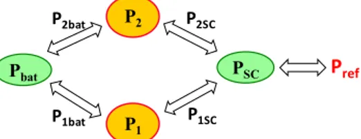
When an EV operates, there is a power demand (Pref) for the
drive system according to the velocity profile. Fig. 3 describes the possible power flows between four sources consisting of the battery package (Pbat), the supercapacitors (PSC), the first
ficti-tious machine (P1) and the second fictitious machine (P2). The
relationships between these powers can be described as follows:
𝑃 = 𝑃 + 𝑃 𝑃 = 𝑃 + 𝑃 ; 𝑃 = 𝑃 + 𝑃 𝑃 = 𝑃 + 𝑃 ; 𝑃 = 𝑃 + 𝑃 𝑃 = 𝑃 + 𝑃 (14-16) where 𝑃 and 𝑃 are power flows between the battery and the first and second machines respectively; 𝑃 and 𝑃 are
ubat ibat Env Tm Tgear Wm m2 uSC iSC SC Bat Wgear Ftrac vveh vveh Fres m1 m1 vveh_ref Ftrac_ref Tgear_ref Tm_ref Wm Wm T1_ref T2_ref uinv1 uinv2 iinv1 iinv2 um im u2 u1 i2 i1 uinv2_ref um_ref ubat_mea
Energy Management Strategy
kP
k1, k2, k3, k4
uinv1_ref Inverters
Sources Coupling Coupling 5-phase PMSM Coupling Gearbox Wheel Chassis Environment
(1-3) (4-5) (6) (7) (8) (9) (10) (11) (12) (13) Energy source Mono-domain conversion element Multi-domain conversion element Accumulation element Coupling element Open-loop control Closed-loop control i2 e2 i1 e1 T2 T1 u1_ref u2_ref i1_ref i2_ref i2_mea e2_mea e1_mea uSC_mea Fres_mea vveh_mea e2_mea e1_mea i1_mea
Fig. 3. Possible power flows of the studied electric vehicle
power flows between the SCs and the first and second machines respectively.
B. Proposed Energy Management Strategy
The proposed EMS allows to manage the powers between the first and the second fictitious machines using the power ra-tio 𝑘 as shown in (17). In addira-tion, in each fictira-tious machine, to control the powers of the battery and supercapacitors, low-pass filters are applied as shown in Fig. 4. The filter time con-stants 𝜏 and 𝜏 , in other words, the cut-off frequencies, can be determined as in [20], depending on response times and sizing of equipment, even the driving cycle. By using the filters, the power flows between the two fictitious machines, battery and SCs can be expressed in (18-19).
𝑘 = = = = (17) 𝑃 = 𝑃 𝑃 = 𝑃 ; 𝑃 = 𝑃 (1 − ) 𝑃 = 𝑃 (1 − ) (18-19) C. Voltage references
When the power partition within the EV system are deter-mined, the voltage references for inverters VSI 1 and VSI 2 can be calculated by using the method of unity power factor for su-percapacitors as presented in [5]. The method allows to charge and discharge the SCs in which the power factor of the second inverter VSI 2, connected to the SCs, equals to 1. Fig. 5a de-scribes an equivalent circuit of the first fictitious machine in d-q frame. The ed-quivalent circuit for the second machine can be expressed similarly. The machine voltage reference vectors in d-q frames (𝑢 , 𝑢 ) of the first and second fictitious machines are determined by voltage vectors (𝑢 , 𝑢 ) of the first in-verter VSI 1 and voltage vectors (𝑢 , 𝑢 ) of the second in-verter VSI 2 as described in (20). Fig. 5b describes the relation-ship between battery and SCs voltages in rotating frame of the first fictitious machine. The relationship between the battery and SCs in the second machine is like the first machine.
𝑢 = 𝑢 − 𝑢
𝑢 = 𝑢 − 𝑢 (20) where 𝑢 = 𝑢 𝑢 and 𝑢 = 𝑢 𝑢 are d-q voltage vectors of the battery and SCs respectively, cor-responding to the first machine; 𝑢 = 𝑢 𝑢 and 𝑢 = 𝑢 𝑢 are d-q voltage vectors of the battery and SCs respectively, corresponding to the second machine.
(a) (b)
Fig. 4. Power distribution between the battery and supercapacitors for: (a) the first machine, (b) the second machine (𝜏 = 𝜏 = 8𝑠)
(a) (b)
Fig. 5. Determine voltage references in the first machine: (a) Equivalent cir-cuit, (b) Voltage distribution in rotating frame using unity power factor
In the first machine, there are 4 d-q voltages (𝑢 , 𝑢 , 𝑢 , 𝑢 ) that need to be defined (21-22). Four d-q voltages (𝑢 , 𝑢 , 𝑢 , 𝑢 ) for the second machine can be similarly calculated as expressed in (23-24). Thus, eight d-q voltage references for the entire system are de-termined. To define the inverter voltage references in the local level of control of the EMR, four ratios 𝑘 , 𝑘 , 𝑘 and 𝑘 be-tween d-q voltage references of VSIs over the d-q total voltage references of the two fictitious machines (𝑢 , 𝑢 , 𝑢 , 𝑢 ) are used and described in (25-26) and Fig. 2.
𝑢 = 𝑢 − 𝑃 𝑢 = 𝑢 − ( )𝑃 ; 𝑢 = − 𝑃 𝑢 = − ( )𝑃 (21-22) 𝑢 = 𝑢 − 𝑃 𝑢 = 𝑢 −( )𝑃 ; 𝑢 = − 𝑃 𝑢 = −( )𝑃 (23-24) 𝑘 = = + 1 𝑘 = = + 1 ; 𝑘 = = + 1 𝑘 = = + 1 (25-26) IV. NUMERICAL RESULTS
The studied EV system is simulated with the parameters as described in Table 1. In this table, parameters of the vehicle, battery, SCs and the electrical machine are given. The 5-phase machine to validate the workability of the drive system in this study is chosen so that the second fictitious machine consists of the third harmonic with its amplitude similar to the first har-monic of the first machine. Therefore, the two machines can share alike powers, leading to more possibilities in power man-agement. In this simulation, the power is equally distributed in-
Pbat PSC P2 P1 P1bat P2SC P1SC P2bat Pref 𝟏 𝝉𝑳𝑷𝑭𝟏𝒔 + 𝟏 𝑷𝟏 𝑷𝟏𝒃𝒂𝒕 𝑷𝟏𝑺𝑪 − + 𝟏 𝝉𝑳𝑷𝑭𝟐𝒔 + 𝟏 𝑷𝟐 𝑷𝟐𝒃𝒂𝒕 𝑷𝟐𝑺𝑪 − + 𝑢 𝑖 𝑅1 𝐿1 𝑒 𝑢 𝑢 q d 𝑖1 𝑢1𝑏𝑎𝑡 𝑢1𝑆𝐶 𝑖𝑞1 𝑖𝑑1 𝑢𝑑1 𝑢𝑞1 𝑢1 𝑢𝑞1𝑏𝑎𝑡 𝑢𝑑1𝑏𝑎𝑡 𝑢𝑞1𝑆𝐶 𝑢𝑑1𝑆𝐶 -𝑢1𝑆𝐶
TABLE 1. PARAMETERS OF THE VEHICLE
Parameter Nomenclature Unit Value
Vehicle
Curb weight mveh kg 692
Rolling resistance coefficient froll p.u 0.02
Aerodynamic standard cwA m2 0.7
Gearbox ratio Kgear 9.32
Battery
Capacity Cbat Ah 102.5
Battery resistance rbat Ω 0.0015
Battery OCV uOCV V 300
Mass kg 330
Supercapacitors
SCs capacitance CSC F 30
SCs resistance rSC Ω 0.04
SCs nominal voltage uSCnom V 90
Mass kg 18.9
5-phase PM machine
Maximal Power Pmax kW 15
Number of phases 5
Number of pole pairs pp 8
Stator resistance R1= R2 Ω 0.0324
Inductance L1 mH 0.102
Inductance L2 mH 0.158
Speed-normalized first harmonic EMF E1n V/rad/s 0.0874
Speed-normalized third harmonic EMF E3n V/rad/s 0.1181
Rated RMS current IRMS A 190
Maximum peak phase current Ipeak A 280
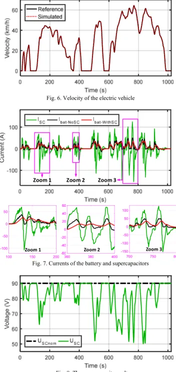
-to two fictitious machines (𝑘 = 0.5). The time constants of the low-pass filters 𝜏 and 𝜏 are set to 8s according to the sizing of the battery and supercapacitors. To verify the stud-ied EV, the velocity profile of Worldwide harmonized Light ve-hicles Test Cycle (WLTC) is applied with the maximum veloc-ity of 64km/h. The driving cycle time is 1022 seconds. The pro-portional controller is used to control speed while the currents are controlled by PI controllers. Fig. 6 shows that the simulated velocity tracks properly the velocity reference.
To verify the changes in battery current with the studied structure, a comparison with the EV using the same machine but in the wye-connected winding configuration fed by single inverter and without SCs needs to be made. In Fig. 7, the battery current with the support of SCs is much smaller with a lower maximum peak value (35A) compared to the case without SCs (50A). At some periods of the operation, the peak values of bat-tery current using SCs are reduced by 50% compared to the case without SCs as shown in zoomed parts of Fig. 7. Moreover, the RMS value of battery current during the driving cycle decreases from 16A to 12A when SCs are used. Thus, from the aforemen-tioned analyses in the introduction section, the battery lifetime can be improved by reducing the RMS battery current.
From Fig. 7, the battery current waveform is smoother, and its values are rarely negative while the SC current is comprised of negative and positive values with the highest peak value up to 153A. Fig. 8 shows that the SCs have been fully recharged to its nominal voltage (uSCnom=90V) at the end of the considered
driving cycle. Therefore, all the regenerative energy is recov-ered to the SCs, which makes the SCs are ready for next opera-tions of the EV. The SC voltage is kept within their limit region from the minimum value (0.5uSCnom) to the nominal value.
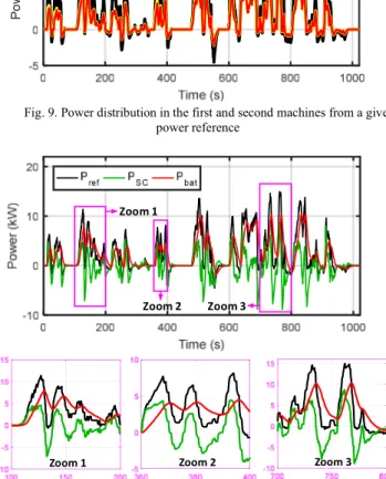
In Fig. 9, because the power ratio between the first and sec-
Fig. 6. Velocity of the electric vehicle
Fig. 7. Currents of the battery and supercapacitors
Fig. 8. The supercapacitor voltage
-ond machines 𝑘 is set to 0.5, the total power reference with the maximal value of 14.9kW is equally shared by the first and second machines. The power distribution between the battery and SCs in the vehicle is shown in Fig. 10. As the above dis-cussions, the processes of charging and discharging of the SCs are frequent while the battery mostly discharges in the driving cycle. It means that the charging number of the battery is re-duced, improving the battery lifetime. In addition, from zoomed parts of Fig. 10, if SCs are not used, the maximum power re-quired for the battery must be equal to the power demand of the entire system with 14.9kW. The stress on the battery power re-duces 30.2% from 14.9kW to 10.4kW when SCs are applied,
C u rr e n t ( A )
Zoom 1 Zoom 2 Zoom 3
100 150 200 -100 -50 0 50 Zoom 1 Zoom 2 700 750 800 -150 -100 -50 0 50 100 Zoom 3 V o lta g e ( V )
Fig. 9. Power distribution in the first and second machines from a given power reference
Fig. 10. Power distribution in the battery and supercapacitors from a given power reference
leading to a reduction in the battery dimension. The maximum power of the SCs is 8.9kW, lower than the power of the battery.
V. CONCLUSION
The modeling and control of an electric vehicle driven by a five-phase permanent magnet synchronous machine in open-end winding configuration has been detailed in this paper. The two 5-phase inverters have been successfully fed by a hybrid energy storage system consisting of a battery and supercapaci-tors. With the proposed energy management strategy, the peak and RMS values of battery current are smoothly reduced, im-proving the battery lifetime. In addition, the energy manage-ment strategy enables to control four power flows within the drive system. The simulation results have validated the worka-bility of the proposed strategy in the considered electric vehicle. In future, other advantages (for example, fault-tolerant capabil-ity) as well as drawbacks of the system and other energy man-agement strategies need to be investigated.
REFERENCES
[1] E. Levi, "Multiphase Electric Machines for Variable-Speed Applica-tions," IEEE Transactions on Industrial Electronics, vol. 55, no. 5, pp. 1893-1909, 2008.
[2] F. Barrero and M. J. Duran, "Recent Advances in the Design, Modeling, and Control of Multiphase Machines Part I," IEEE Transactions on In-dustrial Electronics, vol. 63, no. 1, pp. 449-458, 2016.
[3] P. Sandulescu, F. Meinguet, X. Kestelyn, E. Semail, and A. Bruyère, "Control Strategies for Open-End Winding Drives Operating in the Flux-Weakening Region," IEEE Transactions on Power Electronics, vol. 29, no. 9, pp. 4829-4842, 2014.
[4] O. Béthoux, E. Labouré, G. Remy, and E. Berthelot, "Real-Time Optimal Control of a 3-Phase PMSM in 2-Phase Degraded Mode," IEEE Trans-actions on Vehicular Technology, vol. 66, no. 3, pp. 2044-2052, 2017. [5] B. A. Welchko, "A double-ended inverter system for the combined
pro-pulsion and energy management functions in hybrid vehicles with energy storage," in 31st Annual Conference of IEEE Industrial Electronics So-ciety (IECON), Raleigh, NC, USA, 2005, p. 6 pp.
[6] D. Casadei, G. Grandi, A. Lega, and C. Rossi, "Multilevel Operation and Input Power Balancing for a Dual Two-Level Inverter with Insulated DC Sources," IEEE Transactions on Industry Applications, vol. 44, no. 6, pp. 1815-1824, 2008.
[7] K. K. Mohapatra and K. Gopakumar, "A Novel Split Phase Induction Motor Drive without Harmonic Filters and with Linear Voltage Control for the Full Modulation Range," EPE Journal, vol. 16, no. 4, pp. 20-28, 2006.
[8] E. Levi, M. Jones, and W. Satiawan, "A multiphase dual-inverter sup-plied drive structure for electric and hybrid electric vehicles," in IEEE Vehicle Power and Propulsion Conference, Lille, France, 2010, pp. 1-7. [9] S. M. Rezvanizaniani, Z. Liu, Y. Chen, and J. Lee, "Review and recent advances in battery health monitoring and prognostics technologies for electric vehicle (EV) safety and mobility," Journal of Power Sources, vol. 256, pp. 110-124, 2014.
[10] M. Jafari, A. Gauchia, K. Zhang, and L. Gauchia, "Simulation and Anal-ysis of the Effect of Real-World Driving Styles in an EV Battery Perfor-mance and Aging," IEEE Transactions on Transportation Electrifica-tion, vol. 1, no. 4, pp. 391-401, 2015.
[11] F. Savoye, P. Venet, M. Millet, and J. Groot, "Impact of Periodic Current Pulses on Li-Ion Battery Performance," IEEE Transactions on Industrial Electronics, vol. 59, no. 9, pp. 3481-3488, 2012.
[12] S. F. Tie and C. W. Tan, "A review of energy sources and energy man-agement system in electric vehicles," Renewable and Sustainable Energy Reviews, vol. 20, pp. 82-102, 2013.
[13] B. Nguyen, R. German, J. P. F. Trovão, and A. Bouscayrol, "Real-Time Energy Management of Battery/Supercapacitor Electric Vehicles Based on an Adaptation of Pontryagin's Minimum Principle," IEEE Transac-tions on Vehicular Technology, vol. 68, no. 1, pp. 203-212, 2019. [14] A. Castaings, W. Lhomme, R. Trigui, and A. Bouscayrol, "Comparison
of energy management strategies of a battery/supercapacitors system for electric vehicle under real-time constraints," Applied Energy, vol. 163, pp. 190-200, 2016.
[15] P. Golchoubian and N. L. Azad, "Real-Time Nonlinear Model Predictive Control of a Battery–Supercapacitor Hybrid Energy Storage System in Electric Vehicles," IEEE Transactions on Vehicular Technology, vol. 66, no. 11, pp. 9678-9688, 2017.
[16] O. Gomozov, J. P. F. Trovão, X. Kestelyn, and M. R. Dubois, "Adaptive Energy Management System Based on a Real-Time Model Predictive Control With Nonuniform Sampling Time for Multiple Energy Storage Electric Vehicle," IEEE Transactions on Vehicular Technology, vol. 66, no. 7, pp. 5520-5530, 2017.
[17] Y. Mahadik and K. Vadirajacharya, "Battery Life Enhancement in a Hy-brid Electrical Energy Storage System Using a Multi-Source Inverter," World Electric Vehicle Journal, vol. 10, no. 2, 2019.
[18] A. Bouscayrol, J.-P. Hautier, and B. Lemaire-Semail, "Graphic formal-isms for the control of multi-physical energetic systems," in Systemic Design Methodologies for Electrical Energy: Analysis, Synthesis and Management, X. Roboam, Ed. Hoboken, NJ, USA: Wiley, Oct. 2012, pp. 89-124.
[19] E. Semail, X. Kestelyn, and A. Bouscayrol, "Right harmonic spectrum for the back-electromotive force of an n-phase synchronous motor," in the 39th IEEE Industry Applications Conference, Seattle, WA, USA, 2004, vol. 1, pp. 71-78.
[20] T. Christen and M. W. Carlen, "Theory of Ragone plots," Journal of Power Sources, vol. 91, no. 2, pp. 210-216, 2000.
P o w e r ( kW ) Zoom 1 Zoom 2 Zoom 3