HAL Id: tel-01137779
https://tel.archives-ouvertes.fr/tel-01137779
Submitted on 31 Mar 2015
HAL is a multi-disciplinary open access archive for the deposit and dissemination of sci-entific research documents, whether they are pub-lished or not. The documents may come from teaching and research institutions in France or abroad, or from public or private research centers.
L’archive ouverte pluridisciplinaire HAL, est destinée au dépôt et à la diffusion de documents scientifiques de niveau recherche, publiés ou non, émanant des établissements d’enseignement et de recherche français ou étrangers, des laboratoires publics ou privés.
media using wavefront adaptive holography techniques
in NdYO4
Baptiste Jayet
To cite this version:
Baptiste Jayet. Acousto-optic and photoacoustic imaging of scattering media using wavefront adaptive holography techniques in NdYO4. Other [cond-mat.other]. Université Pierre et Marie Curie - Paris VI, 2015. English. �NNT : 2015PA066039�. �tel-01137779�
THÈSE DE DOCTORAT
DE L’UNIVERSITÉ PIERRE ET MARIE CURIE
Spécialité
Optique physique expérimentale
(ED 564 - Physique en Île-de-France)Préparée à l’Institut Langevin - Ondes et Images Présentée par
Baptiste Jayet
Pour obtenir le grade de
DOCTEUR de l’UNIVERSITÉ PIERRE ET MARIE CURIE
Sujet de la thèse :
Acousto-optic and photoacoustic imaging of scattering
media using wavefront adaptive holography
techniques in Nd:YVO
4Soutenue publiquement le 04/02/2015
devant le jury composé de :
Mme. DA SILVA Anabela Rapportrice M. DAMZEN Michael Rapporteur M. FABRE Claude Examinateur M. BRIGNON Arnaud Examinateur
M. RAMAZ Francois Directeur de thèse M. HUIGNARD Jean-Pierre Membre invité M. ADAM Philippe Membre invité
Université Pierre & Marie Curie - Paris VI Tél Secrétariat : 01 42 34 68 35
Bureau d’accueil Fax : 01 42 34 68 40
Inscription des doctorants et base de données Tél pour les étudiants de A à EL : 01 42 34 69 54
Esc G, 2eétage Tél pour les étudiants de EM à MON : 01 42 34 68 41
15 rue de l’École de Médecine Tél pour les étudiants de MOO à Z : 01 42 34 68 51
Remerciements
B
ien que ce manuscrit n’ait qu’un unique auteur, sa réalisation a grandement bénéficiédes soutiens, encouragements et aides que j’ai pu trouver tant au sein de l’Institut Langevin que dans mon entourage. Je tiens donc maintenant à remercier toutes ces per-sonnes, ami(e)s, familles, collègues, ou simples connaissances, dont la présence m’a été d’une grande aide pour l’achèvement de ces travaux.Tout d’abord je souhaite remercier mon directeur de thèse, François Ramaz, pour la confiance qu’il m’a accordée. Son soutien s’est manifesté dès le début par la recherche de financement pour le projet. Puis tout au long de la thèse à travers d’une part son enthousiasme pour mes résultats, souvent plus grand que le miens. Et d’autre part, par la grande autonomie qu’il m’a laissée ce qui m’as permis d’explorer, de proposer des idées (plus au moins farfelues), de les tester, bref... de chercher!
Quand on commence dans un domaine nouveau et qu’on arrive un peu perdu, avoir un interlocuteur d’expérience est un vrai bonus. Pour cela je tiens à remercier Jean-Pierre Huignard pour les longues discussions que l’on a eues sur la physique des mélanges d’ondes, la diffusion multiple, la modulation acousto-optique et bien d’autres sujets... Son expérience en holographie dynamique m’a été d’une grande aide tout au long de ces trois ans.
Si j’ai pu travailler sur ce projet, c’est aussi grâce aux financements qui lui ont été accordés. Je tiens donc à remercier la Direction Générale de l’Armement et l’Agence National de la Recherche pour nous avoir fourni les moyens financiers nécessaires à l’achat de matériel et pour que je puisse manger pendant ces trois ans.
Ma thèse s’est conclue par la rédaction de ce manuscrit et par la soutenance de mes travaux. Ma gratitude va donc à Anabela Da Silva pour avoir pris le temps de rapporter cette thèse ainsi que pour ses commentaires sur le manuscrit et ma présentation. I would like add Michael Damzen to these acknowledgments. He also accepted to read and
evalu-ate my work had very kind comments regarding my manuscript and my presentation. Je
remercie aussi les autres membres du jury, Arnaud Brignon et Claude Fabre pour l’intérêt qu’ils ont porté à ce travail. Enfin je souhaite aussi remercier Philippe Adam, notre
cor-respondant avec la DGA, pour sa curiosité envers mon travail à travers les discussions que nous avons eues, notamment durant les longues heures de vol vers San Francisco pour
Photonic West.
Je souhaite remercier l’ensemble des membres de l’Institut Langevin pour leur accueil chaleureux. J’ai vraiment pris plaisir à avoir de nombreuses discussions et débats quoti-diens avec plein de gens différents sur des sujets pas nécessairement scientifiques.
Mes remerciements s’adressent aussi à l’ensemble du personnel technique et de gestion du laboratoire qui m’a aidé pour les nombreuses tâches administratives et les commandes de matériel.
Un merci particulier s’adresse à celles et ceux avec qui j’ai travaillé durant ces trois années. D’abord François et Jean-Pierre, cité plus haut, mais aussi les doctorants qui m’ont précédés, Max Lesaffre et Salma Farahi qui m’ont éclairés au départ sur l’acousto-optique. Puis les doctorants et post-doctorants avec qui j’ai partagé la salle de manip et les problèmes expérimentaux, Emilie Benoit, Jean-Baptiste Laudereau, Clément Dupuy et Kevin Contreras. A cela viennent s’ajouter Emmanuel Bossy, Olivier Simandoux, Flo-rian Poisson et Jérôme Gateau pour leurs conseils sur la photoacoustique, et le prêt du laser nanoseconde pour mes expériences du dernier chapitre!
Comment ne pas remercier les joyeux lurons qui ont partager mon quotidien dans mes deux bureaux. D’abord à l’ESPCI : Marc, Karlaa et Emilie, puis après le déménagement, dans le bureau R31 à l’IPG : Emilie (et oui encore!), Nicolas V., Camille, Sylvain, Fabien, Amir, Anne (la génération initiale!) et JB, Olivier T. (continue à parler Handball avec les autres, même quand je ne serai plus la!!), Vincent, Marion (bon courage dans ce bureau masculin!), Clément D., Peng, et sans oublier ni le ficus, ni Yann "Présence" Desailly (les nouveaux occupants!). Merci à vous pour les multiples discussions, utiles et inutiles qu’on a pu avoir, les gâteaux partagés au moment du goûter, les moments en dehors du labo, et la bonne ambiance qui fait que même quand on a la flemme de travailler on vient quand même au labo, et du coup on travaille histoire de ne pas être venu pour rien! Pour ceux d’entre vous qui sont encore là, gardez cette ambiance, essentielle pour avoir une bonne santé mentale! Je vous souhaite bon courage pour la suite (et notamment pour la rédaction)!
Ils et elles n’ont pas partagé mon bureau, mais ça ne nous a pas empêché de passer plein de bon moment. Un merci particulier va donc à Ariadna, Daria et Francois B. pour votre bonne humeur, les pauses cafés, les soirées et les débats (surtout avec Daria!). Merci aussi à Olivier S. pour tes nombreuses questions de physique qui m’ont fait beaucoup re-réfléchir!
Merci également a tous les autres doctorants et post-doctorants du laboratoire, Pierre, Thomas, Matthieu, Nadège (je repars un peu triste qu’on ai pas fini OF), Florian, Lermu, Charlie, Clément P., Nikos, Thu-Mai,... et bien d’autres pour la bonne ambiance générale, les pauses midi avec QPUC, Haxball, et autre jeux sur internet, les verres du vendredi (et des autres soirs)! Je vous souhaite bon courage à tous pour la suite, et particulièrement à ceux et celles d’entre vous qui vont démarrer la rédaction de leur thèse!
iii En dehors du laboratoire je souhaite remercier mes amis d’horizons divers, de Meudon, du Hand,... pour leur présence! Merci particulièrement à ceux qui se sont prêtés au jeu de la relecture de mon manuscrit (sans vraiment comprendre pour certains) : Olivier, Manu, Jonas, Benoit et Dr. BenJ.
Enfin mes derniers remerciements vont à ma famille pour leur soutien. Un merci par-ticulier à mes parents qui m’ont toujours fait confiance dans mes études et m’ont laissé une liberté totale dans mes choix d’orientation en faisant en sorte que je puisse faire mes études dans de bonnes conditions! Je remercie aussi mes frères Cyril (merci pour la relecture d’un chapitre!) et Mikaël ainsi que ma belle-soeur Laetitia pour leur soutien! J’espère que les deux petits nouveaux membres de la famille, Aliénor et Constantin, que j’ai eu la joie d’accueillir pendant cette thèse, s’intéresseront de près ou de loin à la science.
Résumé
L
’imagerie optique des tissus biologiques est un défi du fait de la diffusion de la lumière.Pour sonder les propriétés optiques à quelques cm de profondeur,on peut coupler l’information optique des ultrasons. De cette idée sont nées les imageries acousto-optique et photoacoustique. La première repose sur la modulation de la lumière par des ultrasons balistiques. La seconde se base sur la génération d’ultrasons lors de l’absorption de lumière par un objet.Que ce soit pour l’une ou pour l’autre, l’enregistrement du signal nécessite la mesure de très faibles modulations de phase dans une figure de speckle. L’holographie dynamique est une bonne solution. En effet, les techniques interférométriques sont suffisamment sen-sibles pour mesurer de telles modulations et l’holographie permet de corriger la nature speckle de la lumière. Dans cette thèse nous démontrons la faisabilité de fabriquer un
système d’holographie adaptative basé sur un milieu laser (Nd:YVO4). Un des grands
avantages de ce type de milieu est le temps de réponse. On montrera que le rafraîchisse-ment d’un hologramme dans notre cristal peut se faire en moins de 100 µs, bien inférieur au temps de décorrélation du speckle (≈ ms) qui pourrait grandement perturber les tech-niques de détection plus lentes lors d’expériences in vivo. Trois montages sont présentés ici, le premier pour la détection acousto-optique par conjugaison de phase, le deuxième pour la détection acousto-optique par adaptation de front d’onde et enfin le troisième pour détection photoacoustique. Dans les trois cas on mesure un temps de réponse entre 15 µs et 50 µs, et on utilise le montage pour imager un échantillon.
Mots clés : Imagerie acousto-optique, Imagerie photoacoustique, Holographie dynamique, Conjugaison de phase, Lasers, Milieu diffusant.
Abstract
S
trong scattering properties of biological media make their optical imaging in deptha challenge. A solution to probe the local optical properties is to couple the op-tical information with ultrasound. Two imaging techniques were born from this idea, acousto-optic imaging and photoacoustic imaging. The first technique is based on the local modulation of light by ballistic ultrasound. The latter relies on the emission of ultrasound following the absorption of light by an object.Whether it is acousto-optic imaging or photoacoustic imaging, the recording of the the signal requires a detection system sensitive to weak phase modulation. In addition, the detection system must be compatible with a speckle pattern. Dynamic holography is a good solution. Indeed, as it is based on interferometry, it is very sensitive to small phase variations and holography can be used to correct the speckle nature of light. In this manuscript, we show the use of an holographic detection system based on a laser
medium (Nd:YVO4). One of the main advantage of this type of material is the very fast
response time. It will be highlighted that the recording of a hologram inside our crystal can be done in less than 100 µs, much faster than the speckle decorrelation time (≈ ms), which is one of the major obstacle towards in vivo imaging. Three optical setups will be presented in this manuscript. The first one is a phase conjugation setup for acousto-optic detection. The second one is a wavefront adaption setup, also for acousto-optic detection. Finally, the third setup is an adaptive vibrometry setup for photoacoustic detection. In each setups the measured response time is between 15 µs and 50 µs.
Keywords: Acousto-optic imaging, Photoacoustic imaging, Dynamic hologra-phy, Phase conjugation, Lasers, Scattering medium.
Contents
Introduction ix
I Optical imaging of biological media
1
1 Optical properties of biological media 3
1.1 Propagation of light in multiple scattering media. . . 4
1.1.1 Interaction of light with matter. . . 4
1.1.2 Multiple scattering and diffusion regime. . . 5
1.1.3 Orders of magnitude in biological media. . . 7
1.2 Optical imaging in biology and medicine - Interests and problems. . . 8
1.2.1 Interest of optical imaging . . . 8
1.2.2 Problems related to light scattering. . . 10
1.3 How to perform optical imaging of biological tissue. . . 11
1.3.1 Imaging using ballistic light. . . 11
1.3.2 Imaging techniques based on multiple scattered light. . . 13
1.4 Conclusion. . . 15
2 Ultrasound and light mixing - Acousto-optic and Photoacoustic imaging 17 2.1 Acousto-Optic interaction within multiple scattering media. . . 18
2.1.1 Phase modulation of light by an acoustic wave in a multiple scat-tering medium. . . 19
2.1.2 Properties of the exiting light. . . 22
2.2 Optical imaging with sound - Acousto-Optic Imaging. . . 24
2.2.1 Mapping the local optical properties. . . 24
2.2.2 Resolution of the imaging system. . . 25
2.2.3 Detection of the acousto-optic signal. . . 27
2.3 Principles of Photoacoustic imaging. . . 29
2.3.1 Generate sound with light. . . 30
2.3.2 Ultrasound detection and image reconstruction. . . 31
2.3.3 All optical detection methods. . . 32
2.4 Conclusion. . . 35
II Holography in Nd:YVO
437
3.1 Amplification of light. . . 40
3.1.1 Spontaneous and stimulated emission of light. . . 40
3.1.2 Amplification of light by stimulated emission of light. . . 41
3.1.3 Multi-level systems. . . 43
3.2 Gain saturation phenomenon. . . 44
3.2.1 Rate equations. . . 45
3.2.2 Steady state regime. . . 45
3.3 Hologram recording in gain medium. . . 46
3.3.1 Propagation of light inside a gain medium. . . 46
3.3.2 Spatial modulation of gain. . . 47
3.3.3 Spatial modulation of the index of refraction. . . 49
3.4 Conclusion. . . 51
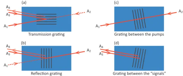
4 Two and Four wave mixing in Nd:YVO4 53 4.1 Two wave mixing in Nd:YVO4. . . 54
4.1.1 Description of the geometric configurations. . . 54
4.1.2 Evolution of the gain. . . 55
4.1.3 Coupled wave propagation in a gain medium. . . 56
4.1.4 Analytical resolution. . . 56
4.1.5 Numerical solution of the coupled wave system. . . 59
4.1.6 With a refractive index modulation. . . 60
4.2 Four-wave mixing in Nd:YVO4. . . 63
4.2.1 Description of the geometric configuration. . . 64
4.2.2 Coupled wave model in steady-sate regime. . . 64
4.3 Conclusion . . . 67
III Detection of Acousto-optic and Photoacoustic signals
by holography in Nd:YVO
469
5 Acousto-optic detection by four-wave mixing in Nd:YVO4 71 5.1 Acousto-optic and optical phase conjugation. . . 725.1.1 Properties of phase conjugate beams. . . 72
5.1.2 State of the art of the use of phase conjugation for imaging. . . 73
5.1.3 Optical phase conjugation for acousto-optic imaging. . . 75
5.2 Experimental realisation of an acousto-optic imaging setup by phase con-jugation in Nd:YVO4. . . 76
5.2.1 Preliminary experiments. . . 76
5.2.2 Optical setup and experimental conditions. . . 81
5.2.3 Setup characterisation. . . 83
5.3 Acousto-optic imaging on a biological sample using phase conjugation . . . 85
5.3.1 Sample and ultrasonic conditions . . . 85
5.3.2 Acousto-optic signal detection by optical phase conjugation . . . 85
5.3.3 Acousto-optic image . . . 87
Contents iii
6 Acousto-optic detection by two-wave mixing in Nd:YVO4 89
6.1 Two-wave mixing for metrology with speckle beams . . . 90
6.1.1 Principles of acousto-optic detection by two-wave mixing. . . 91
6.1.2 State of the art . . . 92
6.1.3 Two-wave mixing acousto-optic detection in Nd:YVO4 . . . 94
6.2 Experimental realisation of an acousto-imaging detection by two-wave mix-ing in Nd:YVO4 . . . 96
6.2.1 Description of the new configuration . . . 96
6.2.2 A few characterisation of the setup . . . 99
6.3 Acousto-optic imaging on a scattering phantom using TWM . . . 101
6.3.1 Samples, ultrasound and acquisition conditions . . . 102
6.3.2 One dimension imaging of a phantom . . . 103
6.3.3 From 1D to 2D. . . 104
6.4 Conclusions and perspectives . . . 106
7 Photoacoustic imaging by speckle vibrometry 109 7.1 Motivation for optical detection of photoacoustic signals. . . 110
7.2 Adaptive gain laser vibrometry on rough surfaces using Nd:YVO4. . . 111
7.2.1 Adaptive gain interferometer . . . 111
7.2.2 Preliminary experiment: Detecting vibration of a Silicon wafer. . . 114
7.2.3 Non-destructive testing perspectives. . . 116
7.3 Ultrasound detection by adaptive gain interferometry. . . 117
7.3.1 Detection of ultrasound inside a phantom. . . 117
7.3.2 Detection of photoacoustic signals. . . 119
7.4 Conclusions and perspectives . . . 123
Conclusions and perspectives 125 A Scientific production 129 B Version courte (FR) 147 B.1 L’optique dans les milieux biologiques. . . 148
B.1.1 Propagation de la lumière dans les milieux biologiques. . . 148
B.1.2 Imagerie optique des milieux biologiques - Intérêts et problèmes. . . 149
B.1.3 Imageries acousto-optique et photoacoustique. . . 150
B.2 Mélange d’onde et holographie dans Nd:YVO4. . . 153
B.2.1 Saturation du gain dans un laser et holographie. . . 153
B.2.2 Mélanges d’ondes dans Nd:YVO4 . . . 154
B.3 Détection AO par mélange à deux et quatre ondes. . . 156
B.3.1 Détection AO par conjugaison de phase. . . 156
B.3.2 Détection AO par adaptation de front d’onde. . . 159
B.4 Détection PA par vibrometrie de speckle. . . 161
B.5 Conclusion et perspectives . . . 164
List of Figures
1.1 Trajectories of photons in a scattering medium. . . 5
1.2 Isotropic scattering and anisotropic scattering. . . 6
1.3 Scattering mean free path and transport mean free path. . . 7
1.4 Absorption in tissues . . . 7
1.5 Comparison of ultrasound imaging and acousto-optic imaging. . . 9
1.6 Effect of scattering of light on background contrast. . . 10
1.7 Types of photons exiting a multiple scattering medium. . . 12
1.8 Classical OCT setup. . . 13
1.9 Principle of Near-InfraRed Spectroscopy. . . 14
2.1 Acousto-optic diffraction. . . 19
2.2 Principle of AOI of multiple scattering sample. . . 19
2.3 Properties of light exiting an insonified scattering medium. . . 22
2.4 Origin of the optical contrast in AOI. . . 23
2.5 Image formation in AOI. . . 24
2.6 Axial resolution of AOI in burst regime. . . 26
2.7 Axial resolution of AOI using random phase jumps. . . 26
2.8 Evolution of the number of tagged and untagged photons. . . 27
2.9 AO images obtained with a fabry-perot based detection. . . 28
2.10 Image reconstruction methods for PA imaging using a focused transducer. . 31
2.11 Image reconstruction methods for PA imaging using an array of transducer. 32 2.12 Schematics of the sensing Fabry-Perot interferometer for PA detection. . . 33
2.13 Problem of spatial coherence while detecting vibration of a scattering sur-face with an interferometer. . . 33
2.14 Wavefront adaption in an interferometer. . . 34
3.1 Radiative deexcitation processes. . . 41
3.2 Amplification of light by a pumped gain medium. . . 42
3.3 Energy levels of a three-level system. . . 43
3.4 Energy levels of a four-level system. . . 44
3.5 Modulation of the population inversion in a gain medium. . . 48
3.6 Gain and refractive index variation vs. frequency detuning in a gain medium. 50 4.1 TWM geometric configuration. . . 54
4.2 Theoretical value of the gain versus time in a TWM configuration. . . 59
4.3 FWM geometric configuration. . . 63
4.4 FWM geometric configuration. . . 64
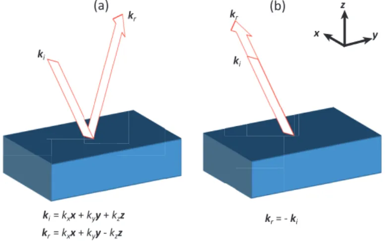
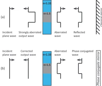
5.1 Difference between a classical mirror and a phase conjugate mirror. . . 72
5.2 Aberration correction using phase conjugation. . . 73
5.3 Amplitude of the phase conjugate signal with and without US. . . 75
5.4 Coating on the crystal . . . 77
5.5 Amplification setup . . . 78
5.6 Gain vs. IIN . . . 78
5.7 Setup for free space phase conjugation of an object. . . 79
5.8 Free space phase conjugation of a collimated wave travelling through an object. . . 79
5.9 Setup for the reconstruction of a point source by phase conjugation . . . . 80
5.10 Reconstruction of a point source through a diffuser by phase conjugation. . 80
5.11 Reconstruction of a point source through a piece of chicken breast by phase conjugation. . . 81
5.12 Optical setup for AO imaging by phase conjugation. . . 82
5.13 Reflectivity of the phase conjugate mirror . . . 83
5.14 Response time of the phase conjugation setup . . . 84
5.15 Phase conjugate signal with and without ultrasound . . . 86
5.16 Phase conjugate signal with and without ultrasound through 8 mm of chicken. 86 5.17 Acousto-Optic image of a piece of chicken breast by phase conjugation . . . 87
6.1 Full orthogonal geometric configuration idea. . . 90
6.2 TWM in a non-linear medium. . . 91
6.3 Computed response of the crystal to a short phase modulation. . . 96
6.4 Geometric configuration for TWM. . . 97
6.5 Photo of the crystal in the TWM experiment. . . 97
6.6 Optical setup for AO imaging by TWM . . . 98
6.7 Gain on TWM setup. . . 99
6.8 Comparison of experimental and theoretical gain in a TWM configuration. 100 6.9 Response time of the holography in TWM configuration. . . 102
6.10 Time diagram of the pump, ultrasound and DAQ triggers for high-speed averaging. . . 103
6.11 AO signal vs. time in a TWM configuration . . . 104
6.12 1 Dimensional scan of a phanton by TWM. . . 105
6.13 Effect of the overlapping of the US focal spot when the sample moves along the y axis. . . 106
6.14 Photo of the inclusions inside the phantom before being covered with a layer of scattering gel. . . 106
6.15 Acousto-optic image obtained by TWM. . . 107
7.1 Beam configurations in the crystal for the PA experiments . . . 111
7.2 Photo of the mounted crystal for the PA experiment . . . 112
7.3 Optical setup for PA detection by TWM . . . 112
7.4 Single-pass gain on PA setup. . . 113
Table des figures vii
7.6 Vibrating paper experiment results. . . 116
7.7 Phantom for the detection of US by TWM. . . 117
7.8 Picture of the phantom for US detection . . . 118
7.9 Ultrasound detection by TWM. . . 118
7.10 Response time of the holography in colinear TWM configuration. . . 119
7.11 Sample for the PA imaging experiment. . . 119
7.12 PA signals . . . 120
7.13 Concatenation of the time signals for different position of the probe spot. . 121
7.14 Multiple paths to probed spot. . . 122
7.15 Reconstructed PA images. . . 123
B.1 Libre parcours moyen de diffusion et de transport. . . 149
B.2 Modulation acousto-optique dans un milieu diffusant. . . 150
B.3 Détection AO par adaptation de front d’onde et conjugaison de phase. . . . 151
B.4 Imagerie acousto-optique. . . 152
B.5 Imagerie photoacoustique. . . 153
B.6 Mélanges à 2 et 4 ondes. . . 155
B.7 Schéma du montage de détection acousto-optique par conjugaison de phase. 157 B.8 Image acousto-optique par conjugaison de phase. . . 158
B.9 Schéma du montage de détection acousto-optique par mélange à deux ondes.159 B.10 Image acousto-optique par mélange à deux ondes . . . 161
B.11 Schéma du montage de détection photoacoustique par mélange à deux ondes.162 B.12 Imagerie photoacoustique. . . 163
Introduction
I
n order to diagnose pathologies, physicians need accurate information about the body.Likewise, biologists also look for information within biological tissues to have a bet-ter understanding of the living. These information can take numerous forms such as qualitative descriptions (sensations, pain,...), values over time (cardiac frequency, blood pressure,...) and sometime images. To see what is inside a biological body, the most obvious path is to send light through the body and try to detect something on the other side. Very quickly, researchers and physicians noticed that light did not work well on biological tissues because of their very strong scattering properties.Physicists looked for new methods of imaging biological tissues. It is during the 20th
century that most of the biomedical imaging techniques used nowadays have been de-veloped. Indeed, the discoveries of radioactivity, X-rays, piezoelectricity, and nuclear magnetic resonance have enabled the invention of new imaging modalities such as PET, X-ray imaging, ultrasound imaging and MRI. These very powerful methods have been rapidly adopted by physicians and biologists in order to get information from deep inside human and animal bodies. They all worked really well because they rely on waves (ultra-sonic waves, RF electromagnetic waves,...) that propagate well inside biological tissues. Due to these good performances, the biomedical community lost interest into biomedical optics for a few decades. Nevertheless, recently the interest for optics in biology came back because of the limitations of certain imaging techniques. Indeed, as an example, the early detection of tumours remains a challenge, yet, it is crucial in cancer treatment. The difficulty resides in the small size of early tumours and in the fact that current techniques cannot always differentiate healthy tissues from cancer cells.
Optic, because it provides access to a lot of new information, can be a great support to current imaging techniques. As light interacts with matter constituents, optical imaging gives access to information such as chemical composition. In addition, the changes in com-position of biological tissues can be linked to structural information. If added to current imaging techniques, the richness of information provided by optics can greatly enhance medical diagnosis and biological research. To overcome the problems of light scattering, physicists developed promising new techniques coupling light with ultrasound in order to
retrieve the optical information deep inside tissues with the good resolution provided by ultrasound imaging. From these investigations, acousto-optic and photoacoustic imaging were born during the 1990s. These two imaging techniques are based on the eponymous effects.
Acousto-optic is the modulation of light with an acoustic field. By locally tagging photons within a biological tissue with an acoustic field in the ultrasound domain -it is possible to retrieve the local optical properties of the sample. The main challenge is the detection of the so called tagged photons, since there are very few of them and the tagging corresponds to a very small frequency shift compared to the light frequency. During the past twenty years, research was aimed at developing detection techniques of the
tagged photons to retrieve acousto-optic signals with a good SNR. They were based either
on narrow spectral filtering or on adaptive holography. The team at Institut Langevin, formerly Laboratoire d’Optique Physique, worked on acousto-optic imaging for the past fifteen years. They mainly developed detection methods based on adaptive holography using the photorefractive effect or using digital holography. This led to promising results on phantoms or ex vivo samples. The next step, performing real in vivo imaging, requires to overcome the issue of speckle decorrelation. This concern, shared with the other teams around the world working with coherent detections, can be a major obstacle since the light coming from a living sample is not stable in time. Due to inherent biological movements (blood flow, heart beats, breathing,...), it decorrelates in around 1 ms. Hence, holographic systems need to be able to record holograms faster than this decorrelation time. In common photorefractive crystals, the response time is usually between 1 ms and 100 ms, which may not be fast enough for in vivo imaging.
This was the main motivation for the work described in this manuscript. Our goal was to demonstrate the feasibility of an holographic detection system based on a gain
medium (Nd:YVO4) with a sub-millisecond response time. In addition, our optical setup
was used for another biomedical imaging technique: photoacoustic imaging. We managed to perform the detection of photoacoustic signals without any contact on the sample.
This manuscript is organised into three parts. The first part describes, through two chapters, light propagation in biological tissues and how it can be used to perform imag-ing. The first chapter is dedicated to the optical properties of biological tissues and the propagation of light inside them. Chapter 2 describes the interactions of light with ul-trasound and how they can be used to perform acousto-optic imaging and photoacoustic imaging. The second part of the manuscript is dedicated to the main tool used for the de-tection of acousto-optic and photoacoustic signal: holography in gain media. It is divided into two chapters. The first one explains the processes of amplification and wave mixing in a gain medium. And the second one details the particular cases of two-wave mixing and four-wave mixing through mathematical models. Finally, part III of this manuscript reports our experimental investigations. It is divided into three chapters. First, chapter 5 shows the detection of acousto-optic signals using phase conjugation by four-wave mixing
in Nd:YVO4. We demonstrate acousto-optic imaging with a response time around 15 µs.
In chapter 6, another geometric configuration is investigated. It produced interesting re-sults using wavefront adaption by two-wave mixing as a detection process. We performed
Introduction xi the acousto-optic imaging of a phantom with a response time of 45 µs. The final chapter explores the use of two-wave mixing for the detection of vibration at the surface of a mul-tiple scattering sample. We applied this detection to contactless photoacoustic imaging of wires hidden behind chicken breast with a response time of 25 µs.
The conclusion of this manuscript will sum up the work achieved during the past three years. Then the perspectives opened by this work will be discussed in order to propose new ideas. The stakes being either the improvements of biomedical imaging (acousto-optic and photoacoustic) or the development of new applications of holography in gain media non necessarily related to biomedical imaging, e.g., non-destructive testing.
Part I
CHAPTER
1
Optical properties of biological media
Contents
1.1 Propagation of light in multiple scattering media. . . 4
1.1.1 Interaction of light with matter. . . 4 1.1.2 Multiple scattering and diffusion regime. . . 5 1.1.3 Orders of magnitude in biological media. . . 7 1.2 Optical imaging in biology and medicine - Interests and problems. . . 8
1.2.1 Interest of optical imaging . . . 8 1.2.2 Problems related to light scattering. . . 10 1.3 How to perform optical imaging of biological tissue. . . 11
1.3.1 Imaging using ballistic light. . . 11 1.3.2 Imaging techniques based on multiple scattered light. . . 13 1.4 Conclusion. . . 15
B
iological tissues are composed of complex structures (cells, membranes, fiber,...) thatmake the propagation of light very complicated. These structures strongly interact with light through two main phenomena: absorption and scattering. The first decreases the intensity of the light whereas the latter changes the trajectory of the photons travelling through the sample. This results in a large dispersion of light in every direction after a few millimetres of propagation in a biological tissue.This chapter starts by presenting the different phenomena that govern the interactions of light with matter. We will see the different regimes of propagation and how they affect light along its propagation in a biological sample. Then, we will expose the interests of optical imaging inside biological media despite the complications due to the strong interaction of light with those media. Finally, we will discuss the different solutions that currently exist in order to retrieve the optical properties of biological tissues.
1.1 Propagation of light in multiple scattering
me-dia.
1.1.1 Interaction of light with matter.
The two main phenomena that occur when light propagates inside a multiple scattering medium are absorption and scattering. Depending on their relative magnitude, they can have a strong effect on how light exit a sample and on our ability to get optical information from inside the sample.
Absorption Absorption is the result of the interaction of light with the transition levels
of the atoms (electronic transition) and/or molecules (electronic, vibrational,...) that compose the medium. If the energy of the photons matches a transition energy, it can be absorbed. The absorbed energy is then dissipated through various processes that can be non radiative, e. g. heat, or radiative, e. g. fluorescence or phosphorescence. Absorption
is characterised by the absorption coefficient µa which links the decrease of the flux of
a collimated light beam to the distance travelled by light in the medium through the following equation:
Φ(z) = Φ0 e−µaz (1.1)
where Φ(z) is the flux at depth z, Φ0 is the incident flux and z is the distance travelled by
light. The absorption coefficient µa is usually expressed in cm−1. This relation is known
as the Beer-Lambert law and is valid for non scattering medium. Absorption can also
be described by the absorption mean free path la, which is the inverse of the absorption
1.1. Propagation of light in multiple scattering media. 5
Scattering Some media have a complicated microstructure, their refractive index is
inhomogeneous at the microscopic scale or less. When light travels in such medium, it takes random path because it encounters scatterers, which randomly change the direction of propagation as illustrated in Fig. 1.1. As a result, photons exit the sample with a
Sca#ering medium
Incident light
Mul"ple sca#ered light
Figure 1.1– Trajectories of photons inside a scattering medium.
random direction and phase, this process is called scattering. It can be described by Mie theory which works for inhomogeneities, or scatterers, that have the size of the wavelength or larger. For scatterers much smaller than the wavelength, approximation can be made and Mie scattering is simplified into Rayleigh scattering.
In the same way absorption is described by the absorption coefficient µa, scattering is
described by the scattering coefficient µs. It characterises the loss of photons travelling
in a straight line through the sample, which we will call ballistic light. This coefficient is
expressed in cm−1, so the flux transmitted in a ballistic way trough a medium of thickness
z can be written:
Φbal(z) = Φ0 e−µsz (1.2)
The scattering mean free path, which is the inverse of the scattering coefficient: ls= 1/µs,
can be interpreted as the average distance travelled by a photon between two scattering events.
1.1.2 Multiple scattering and diffusion regime.
The scattering mean free path can be used to introduce the notion of multiple scattering. When propagating through a medium, photons can be scattered many times depending on the relative thickness of the medium compared to its scattering mean free path. Three regimes can be defined for a medium with a thickness L:
• L ≪ ls: Ballistic regime, photons are almost not scattered.
• L ≃ ls: Simple scattering regime.
• L ≫ ls: Multiple scattering regime.
In the ballistic regime, light propagating in a ballistic way is almost not attenuated because of scattering, only by absorption (if the medium is absorbent). The multiple scattering regime is the opposite: the collimated beam is totally extinguished, the trans-port of the electromagnetic energy is done only through diffused light. Finally, the simple scattering regime is a combination of both: collimated light and diffused light coexist.
Extinction coefficient In an absorbent and scattering medium, the loss of energy of a
collimated beam is due to both absorption and scattering. It is then possible to define the extinction coefficient: µe = µa+ µs, which reflects the total attenuation of a collimated
beam propagating through a medium with the relation: Φcol(z) = Φcol(0) exp(−µez).
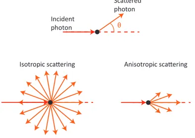
Anisotropy In fact, when scatterers are larger than the wavelength, the probability
distribution of θ, defined as the angle between the initial direction, and the direction after the scattering event (see Fig. 1.2), is no longer uniform. In this case the scattering is said to be anisotropic, as opposed to the isotropic scattering when the photons have the same probability to go in any direction. The anisotropy can be quantified using the anisotropy
θ
Incident photon
Sca ered photon
Isotropic sca ering Anisotropic sca ering
Figure 1.2– Isotropic scattering and anisotropic scattering.
coefficient defined as the expected value of the cosine of θ:
g = hcos(θ)i (1.3)
From this, it is possible to derive a new scattering coefficient µ′
s and a new mean free
path l′
s, respectively called the reduced scattering coefficient and the transport mean free
path. They can be expressed as functions of the scattering coefficient µs, the scattering
mean free path ls and the anistropy g:
µ′s = µs(1 − g) (1.4) l′ s = 1 µ′ s = ls 1 − g (1.5)
The transport mean free path l′
s can be interpreted as the depth at which a photon, that
underwent multiple scattering event, has lost the information about its initial direction and polarisation. The difference between ls and l′s is illustrated in Fig. 1.3.
Effective extinction coefficient If the thickness of the medium is larger than the
transport mean free path, L ≫ l′
1.1. Propagation of light in multiple scattering media. 7
l
S’
l
SFigure 1.3– Scattering mean free path and transport mean free path.
by the effective extinction coefficient defined as: µef f =
q
3µa(µa+ µ′s) (1.6)
In this case, the flux of the light at a distance z from the entrance of the medium is given by:
Φ(z) = Φ0e−µef fz (1.7)
1.1.3 Orders of magnitude in biological media.
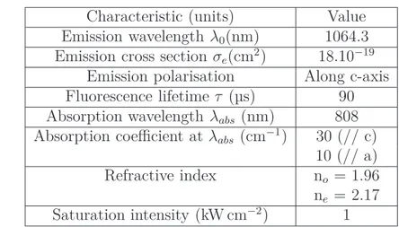
Biological tissues are composed of a lot of different substances having various refractive indices. As an example, water has a refractive index of 1.33, lipids of 1.46 and proteins of 1.54. Depending on the exact composition of a tissue, its refractive index is usually between 1.33 and 1.5.
Optical therapeutic window Absorption in biological tissue is mainly due to water
and haemoglobin. Their absorption spectra is given in Fig. 1.4, where we can see that haemoglobin strongly absorbs at wavelength shorter than 600 nm, and water is strongly absorbent at wavelength longer than 1300 nm. As a result, to exploit light for imaging inside biological media, one needs to stay within the so called optical therapeutic window which is usually the wavelength range [600 nm ; 1300 nm].
h#p://rsfs.royalsocietypublishing.org/content/royfocus/early/2011/06/21/rsfs.2011.0028.full.pdf Copyrighted content.
Original figure can be found at:
Scattering Light in the optical therapeutic window can propagate quite deeply, a few
cm, without being absorbed in biological sample. Yet, imaging deep inside tissues remains a challenge due to their strong scattering properties. Despite a very strong scattering coef-ficient µs, between 50 cm−1and 200 cm−1, light still propagates deeply in biological tissues
because of the anisotropy of the scattering. Indeed, during a scattering event, photons are mainly forward scattered enabling a deep penetration of light inside tissues. The anisotropy coefficient is between 0.8 to 0.99, so the usual value of the reduced scattering coefficient used to describe tissues is µ′
s= 10 cm−1.
Table 1.1 sums up the optical properties of biological sample in the optical therapeutic window. These values are issued from [2].
n Refractive index 1.33 – 1.5
µa Absorption coefficient 10−2cm−1 – 10 cm−1
µs Scattering coefficient 50 cm−1 – 200 cm−1
g Anisotropy 0.9 – 0.99
µ′
s Reduced scattering coefficient 10 cm−1
µef f Effective extinction coefficient 1.5 cm−1 – 60 cm−1
Table 1.1– Optical properties of biological tissues.
1.2 Optical imaging in biology and medicine -
In-terests and problems.
The variety of imaging techniques (MRI, ultrasound imaging, CT scan, X-ray imaging,...)
that have been developed during the 20thcentury gives access to a lot of information on the
studied subject, but they are mainly structural. They can be completed with methods such as Positron Emission Tomography (PET) to have metabolic information. In this section we first discuss how optical imaging can improve diagnosis by giving physicians new tools and new information to come up with accurate diagnosis and perform the right treatment. Indeed, as light interacts with the constituent of the body it can provide helpful information about composition or metabolism. The second part of this section is focused on the problems due to multiple scattering of light inside biological tissues and the difficulty of mapping their local optical properties.
1.2.1 Interest of optical imaging
Non-invasive Light in the visible and Near Infra-Red (NIR) part of the spectrum is
attractive for biological imaging purposes. At these wavelengths, electromagnetic radi-ations are non-ionising and relatively harmless for biological tissues. Optical imaging is thus completely safe and provides information about tissues without causing any damage.
1.2. Optical imaging in biology and medicine - Interests and problems. 9
Enhancing detection Interaction of light with matter is mainly due to interaction of
light with the atoms and molecules constituting the tissues. This means that the contrast given by an optical imaging technique can provide information about composition whereas techniques such as ultrasound imaging or X-Ray provide structural information. As an example, Pogue et al. showed in 2001 that diffuse optical tomography enabled to image haemoglobin concentration, which led them to image breast tumour (fibroadenoma and carcinoma) [3]. In 2014, Laudereau et al. used acousto-optic imaging in addition to ultrasound imaging to see tumour on a liver biopsy [4] as shown in Fig. 1.5. It represents the photography of an ex vivo liver sample with tumours (d), the ultrasound image(a) and the acousto-optic image (b) and (c). These two examples show that light has a great potential to add meaningful information to current imaging techniques.
A xi al p o si o n Z ( m m ) 0.2 0.4 0.6 0.8 1 0.1 0.06 25 20 15 0 5 10 15 20 25 30 A xi al p o si o n Z ( m m ) 10 15 20 25 (c) AO Signal (mV)
AO log contrast (a.u.)
30 25 20 15 Transverse position X (mm) 30 0.02 (b) (a) (a) (d) 0 25 20 15 Transverse posion X (mm) 30 35 40 45 0 -67 US Signal (dB) -0.02
Figure 1.5 – (a) Ultrasound image of a liver biopsy embedded in a scattering gel made of Agar and Intralipid. (b) Acousto-Optic image of the liver biopsy. (c) Acousto-Optic image with a subtracted envelop. (d) Picture of the biopsy before being embedded in the scattering gel. (taken from [4])
Metabolic information Figure 1.4, shows the absorption spectra of naturally present
chromophores in biological tissues, especially haemoglobin and oxyhaemoglobin. There is a significant difference in the absorption coefficient of those two species for wavelengths between 750 nm and 800 nm. This means that it is theoretically possible to map the concentration of haemoglobin and oxyhaemoglobin by performing optical imaging at two different wavelengths. This is very interesting for medical purposes since the information of blood oxygenation is an essential parameters that physicians use everyday to monitor their patients’ health.
Molecular imaging Some techniques, such as PET, use radioactive markers that are
it is possible to localise the marked cells. A similar imaging system can be realised by combining diffuse optical tomography and fluorescent markers. With this method, it is possible to map the local concentration of some fluorescent probes without using radioactivity [5]. This can lead to the detection and the study of tumours directly in vivo "without any stress or damage to the animal" as written by Koenig et al. [6].
1.2.2 Problems related to light scattering.
We have outlined that using light for in vivo imaging has very interesting applications. As light from the red and NIR part of the spectrum is not strongly absorbed, it can be used to perform optical imaging. Unfortunately, biological tissues have very strong scattering properties for light waves, which makes optical imaging difficult. Indeed, usual optical imaging techniques such as photography or microscopy rely on ballistic light. When light propagates in a scattering medium, standard imaging techniques are not possible anymore. The picture in Fig. 1.6, illustrates this phenomenon, the further the mountains in the background are, the less visible they are. It is due to the fact that, when the
Figure 1.6– Effect of light scattering on background contrast.
picture was taken, the atmosphere was not very clear and scattered light. As a result, light from far away underwent more scattering events and was more attenuated resulting in a lower contrast. In addition, scattering made parasitic light going into the direction of the camera. In the case of this picture, the atmosphere is very lightly scattering, enabling taking pictures of object a few kilometres away, biological tissues are so scattering that after a few millimetres, it is impossible to perform standard optical imaging.
A quick calculation gives an idea of the attenuation of ballistic light in multiple scat-tering media such as biological tissues. Let us consider light at 1064 nm (this wavelength is chosen because it is the one used in all the experimental work described in this thesis).
At this wavelength, biological tissues have the following characteristics: µa ≈ 0.1 cm−1,
1.3. How to perform optical imaging of biological tissue. 11
light is given by the extinction coefficient µe, meaning that after propagating through
L = 1 cm, the transmitted ballistic light is e−µeL ≃ e−100 ≈ 10−44, we might as well
con-sider that there is no exploitable ballistic light. Besides, the attenuation of diffused light
is much weaker and can be calculated using the effective extinction coefficient µef f. For
the same thickness of L = 1 cm, the remaining diffused light is e−µef fL ≃ e−2 ≈ 10−1. This
shows that using ballistic light for biological tissue imaging is difficult, and the solution might be in finding techniques that exploits diffused light.
1.3 How to perform optical imaging of biological
tissue.
Despite the difficulty of doing optical imaging in biological sample, a few solutions exists and are investigated. They can be separated into two categories: solutions that rely on
ballistic or snake photons1, and solutions that choose to take advantage of the multiple
scattered light. This section describes both approach starting with solutions that use ballistic light. The techniques that rely on mutliple scattered light to probe the local optical properties of biological medium are presented in the second part of this section.
1.3.1 Imaging using ballistic light.
Trying to exploit ballistic light is very attractive since it is equivalent to achieving imaging in the conventional sense. As ballistic photons do not undergo scattering event, their trajectories are governed by the laws of geometric optics, which means that they are easy to exploit for imaging with a very good resolution. The main problem is that their number decreases very rapidly inside biological tissues. As a result, after a few millimetres, they are very few compared to the multiple scattered ones that constitute parasitic light. In order to use ballistic photons, it is necessary to reject diffused light so that only the ballistic or snake photons reach the detector.
Snake photons Photons exiting a multiple scattering medium can be sorted in three
types. First the ballistic photons, they are the ones that have not been scattered and that are labelled (a) on Fig. 1.7. In the case of biological medium, which have strong scattering properties, there are very few of them. The second type of photon are the snake
photons, labelled (b) on Fig. 1.7. These photons underwent only several scattering events
so their trajectory is very close to the trajectory of the ballistic photons, consequently, they can be used in imaging techniques based on ballistic light, at the cost of degrading the resolution. Finally, the third type of photons is the scattered ones (c), as they have been multiply scattered by the medium, their path inside the medium is random. They are the most numerous at the exit of a biological sample.
1
The snake photons are the photons that have been scattered only several times so their trajectory is very close to the ballistic photons trajectory.
Incident light (a) (b) (c) (c) (c) Sca!ering medium
Figure 1.7 – Types of photons exiting a multiple scattering medium. (a) Ballistic photons, (b) Snake photons and (c) Scattered photons.
It is possible to isolate ballistic light from diffused light using spatial or time gates [7]. Gating light makes optical imaging of multiple scattering medium possible, but with a very limited depth, usually a few millimetres, because of the very fast attenuation of ballistic light.
Spatial gating The definition of ballistic photons is that they have not been deviated by
scattering. As they travel in straight lines, they can be isolated using a simple collimator. With a collimator in front of the detector aligned with the source, it is possible to isolate the photons that travelled in straight line between the source and the detector. This way only the photons with a propagation direction parallel to the initial direction will be detected. Another idea consists in using Fourier filtering with a lens in order to eliminate high frequency components. Then, with a point by point scanning it is possible to reconstruct the absorbing part of the sample. These techniques are still very limited because of, first, the small number of ballistic photons and second, the scattered photons that still manage to go through the collimator.
Temporal gating Another way of filtering the ballistic and snake photons is to use time
gating. As mentioned earlier, the ballistic and snake photons travel in almost straight line. This means that in a short light pulse, they are the first to arrive at the detector because they took the shortest possible path. As a result, a femtosecond laser pulse will be enlarged in the time domain because of scattering and with a fast time gate, around a few picosecond, it is possible to isolate the ballistic and snake photons from the multiple scattered ones. A few methods exist in order to create short time gate such as the use of streak cameras or non-linear processes using a femtosecond laser pulse. The non linear processes can be Kerr effect [8], stimulated Raman scattering [9] or Optical Parametric Amplification [10].
Optical Coherence Tomography The last method of filtering ballistic light from
multiple scattered light is by using coherence. When illuminating a sample with a low time-coherence light source, the only photons that remain coherent during their travel through the multiple scattering sample are the ballistic photons or the backscattered photons that have been scattered only once. This is the basic principle of the imaging
1.3. How to perform optical imaging of biological tissue. 13 technique called Optical Coherence Tomography (OCT) proposed by Fujimoto’s team [11] in 1991. A classic scanning OCT setup is represented in Fig. 1.8.(a) along with images of human breast tissues obtained by Full-Field OCT (Fig. 1.8.(b)). Since then, OCT has been developed a lot and has numerous applications in various medical field such as ophthalmology, dermatology and even dentistry [12]. It is probably the most advanced technique based on the use of ballistic light in order to perform imaging on multiple scattering media. It is able to generate images with a resolution around 1 µm at depth up to 1 mm. More recent work tried to combine OCT with other imaging techniques in order to add new contrasts to OCT images such as elastography [13] or photothermal imaging [14].
(a) (b)
Figure 1.8 – (a) Classical scanning OCT setup (From Wikipedia). (b) En face Full-Field OCT images of fixed human breast tissue at depth 40 µm on two different areas (From [15])
The use of ballistic photons is a great advantage because it leads to a very good spatial resolution, but it also has limitations. As mentioned earlier, the number of ballistic photons decreases very rapidly. The imaging depth is therefore very limited since after a few millimetres there is not enough light to perform imaging. In order to get optical information from deep inside tissues, it is necessary to find methods that exploit multiple scattered light.
1.3.2 Imaging techniques based on multiple scattered light.
Diffused light coming from a multiple scattering medium creates very complicated patterns that seem to carry no information about the medium. In fact, the interesting information (local absorption for example) is blurred into the diffused light pattern and is very hard to isolate. In this section, we will explore different solutions that have been implemented in order to retrieve interesting information from multiple scattered light. These methods can be separated into two categories:• Methods that use detailed model and equation describing the propagation of light in complex media in order to reconstruct the optical field inside the sample (NIRS and DOT)
• Methods that couple optics to another type of wave that propagates ballistically (ultrasound) in order to carry the useful information (photoacoustic and acousto-optic).
NIRS NIRS is for Near-InfraRed Spectroscopy, this method enables to probe the optical
properties of tissues at depth around 50 mm. It uses the fact that between a light source and a detector on the surface of a tissue, light propagates in a banana-shaped volume as shown in Fig. 1.9. As a result, light collected by the output fiber will carry information about the absorption along the "banana-shaped" path. This technique is not, strictly
Sca#ering medium Input light Output light
Diffused light paern “Banana shaped”
D D/2
Figure 1.9 – Principle of Near-InfraRed Spectroscopy – The path travelled by light in a multiple scattering media between a source and a receptor spaced by D has the shape of a banana that goes at a depth of D/2
speaking, an imaging technique since the collected information is not localised in space, it is the global absorption along a certain path. Nevertheless, it is possible to probe the absorption at different depth by changing the distance between the input fiber and the output fiber. For a distance D between the emitter and the receptor, the probed depth will be around D/2. Moreover, as the name suggests, it is possible to perform spectroscopy by scanning a range of wavelength, in order to calculate, for example, blood oxygenation. Since it has been proposed, by F. Jöbsis in 1977 [16], NIRS has been developed in a variety of modalities (NIRS-CW, NIRS-TD and NIRS-FD, for Continuous Wave, Time Domain and Frequency Domain) in order to improve depth and reduce measuring time.
Diffuse Optical Tomography The propagation of light in multiple scattering medium
can be mathematically modelled using the Radiative Transfer Equation (RTE). The idea of DOT is to use the RTE to mathematically model the propagation of light inside a sample using the local optical properties (absorption and scattering coefficients) as parameters. Then a large number of optical fibres placed all around the sample are used as light sources and detectors in order to record the scattered light at the edge of the sample for different boundary conditions. Using the different boundary conditions, it is possible to solve the inverse problem in order to calculate the optical properties of the sample.
DOT has been implemented in commercial devices and can be used for brain imag-ing [17] or breast cancer imagimag-ing [18]. It gives 3D images of the optical properties of biological medium with a spatial resolution that depends on the algorithm and numerical parameters such as the mesh, the number of light sources and the number of receptors.
1.4. Conclusion. 15 The thinner the mesh is, the better the resolution, but the longer the numerical calcula-tions. The resolution is typically 5 mm which is very limited for, e. g., early detection of tumours which can be smaller than 1 mm. Nevertheless, as mentioned in 1.2.1, DOT can be used to track fluorescent probes with specific markers injected inside a patient. This method, called Fluorescence Diffuse Optical Tomography (FDOT) [19], is not, strictly speaking, an optical imaging method because the images generated do not give informa-tion about the optical properties of the sample. However coupled with standard DOT it is possible to add useful information to DOT images.
Another way of using diffused light to gather information from inside a multiple scatter-ing medium is to couple light with another wave that propagates well in the medium such as ultrasound (in the case of biological sample). This can be done using the photoacoustic effect or the acousto-optic effect.
Photoacoustic imaging It is possible to generate acoustic waves with light. When a
short light pulse hits an absorber, it briefly expands and generates an acoustic wave in the medium. This is called the photoacoustic effect. The position and size of the absorber can then be determined by detecting the generated acoustic wave. A paragraph of this manuscript, in chapter 2, is dedicated to the principles of photoacoustic imaging in order to introduce the experiments from chapter 7 on an optical detection of photoacoustic signals.
Acousto-optic imaging Light and ultrasound can interact through the acousto-optic
effect which is the basic principle behind Acousto-Optic imaging, also known as Ultra-sound modulated Optical Tomography. As photons travel through an acoustic field, they are phase modulated. Then, by detecting the phase modulated signal, it is possible to image the local optical properties of the medium. As acousto-optic imaging is the main subject of this thesis, a large part of chapter 2 describes its functioning. Chapters 5 and 6 are dedicated to our experimental investigations on the use of holography in gain media for the detection of the acousto-optic phase modulation.
1.4 Conclusion.
In this introduction chapter we presented the main optical properties of biological tissues. We saw that they were strongly scattering for optical waves, which implies that it is quite hard to perform optical imaging at high depth. Yet, information provided by optics could be very helpful for physicians to improve diagnosis by adding new informations when used in conjunction with other imaging techniques. Moreover, light waves are virtually harmless for biological tissue. Using them for imaging is therefore a very promising approach. We presented a few techniques that tried to exploit light that propagates in a ballistic way inside biological tissues, but we saw that these methods were very limited in terms of imaging depth.
purely optical techniques exists such as diffuse optical tomography or NIRS but their res-olution is very limited. Finally we introduced two techniques based on coupling light with ultrasound: Acousto-Optic imaging and Photoacoustic imaging. They will be detailed in the next chapter.
CHAPTER
2
Ultrasound and light mixing - Acousto-optic and Photoacoustic
imaging
Contents
2.1 Acousto-Optic interaction within multiple scattering media. . . 18
2.1.1 Phase modulation of light by an acoustic wave in a multiple scattering medium. . . 19 2.1.2 Properties of the exiting light. . . 22 2.2 Optical imaging with sound - Acousto-Optic Imaging. . . 24
2.2.1 Mapping the local optical properties. . . 24 2.2.2 Resolution of the imaging system. . . 25 2.2.3 Detection of the acousto-optic signal. . . 27 2.3 Principles of Photoacoustic imaging. . . 29
2.3.1 Generate sound with light. . . 30 2.3.2 Ultrasound detection and image reconstruction. . . 31 2.3.3 All optical detection methods. . . 32 2.4 Conclusion. . . 35
D
ue to multiple scattering of light inside biological tissues, it is no longer possible tohave local information about the properties of the medium. One way of mapping the optical properties of the medium such as the absorption coefficient or the scattering coefficient is to couple light with another wave that propagates "well" (in a ballistic way). In biological tissues, ultrasonic waves are a good candidate since they propagate with almost no scattering and little attenuation at echographic frequencies (several MHz).There are two ways of using light and ultrasound in order retrieve the local optical properties of a multiple scattering medium. The first idea is to use the acousto-optic effect, which is the modulation of light by an acoustic field. This technique is called
Acousto-Optic Imaging (AOI) or Ultrasound Optical Tomography (UOT). The second
idea is to use the generation of ultrasounds inside the medium through the photoacoustic effect. The original idea of this thesis was to develop a detection system for AOI based on holography in gain media. The first two sections of this chapter are dedicated to the principles and the challenges of acousto-optic imaging (our experimental investigations concerning AOI is the subject of chapters 5 and 6). As we noticed that our setup could be used to detect vibrations on a scattering surface, we also demonstrated the detection of photoacoustic signals. Therefore, the last section of this chapter outlines the principles of photoacoustic imaging in order to introduce the experiments described in chapter 7.
2.1 Acousto-Optic interaction within multiple
scat-tering media.
Diffraction of light by an acoustic wave has been predicted in 1921 by Brillouin. A few years later, in 1932, P. Debye and R. Lucas independently brought the experimental demonstration of this phenomena [20, 21]. The pressure wave creates a refractive index grating that diffracts light waves propagating through the acoustic field. There are two effects of this diffraction on a beam travelling in an acoustic field (see Fig. 2.1). First the
diffracted components (in a normal incidence) are deflected by an angle θm given by the
following equation:
Λ sin(θm) = mλ (2.1)
where Λ is the acoustic wavelength, λ is the optic wavelength and m is the diffraction order. In addition to the angular deflection, the diffracted components are frequency
shifted, the light diffracted in order m has a frequency of fm = fL+ mfac, where fL is
the input light frequency, and fac is the acoustic frequency. The frequency shift, which
is due to a phase modulation, is the key of AOI of thick scattering medium, as it is the origin of the signal we will try to measure.
2.1. Acousto-Optic interaction within multiple scattering media. 19 Order 0 +1 +2 -1 -2 Acous c emi"er Frequency fL fL fL + fac fL + 2fac fL - fac fL - 2fac
Figure 2.1 – Diffraction of light, in the Raman-Nath regime, by a refractive index grating generated by an acoustic wave.
2.1.1 Phase modulation of light by an acoustic wave in a
mul-tiple scattering medium.
In a scattering medium, the interaction between light and an acoustic field is different from the case without scattering. As the light is not propagating in a straight line anymore, but taking random path through the medium, talking about deflection of the beam has no longer any meaning.
Nevertheless, light is still phase modulated by the acoustic wave. Two mechanisms are responsible for this modulation of the optical wave. First, the modulation of the refrac-tive index, due to the pressure changes, modulates the phase of the optical beam. In
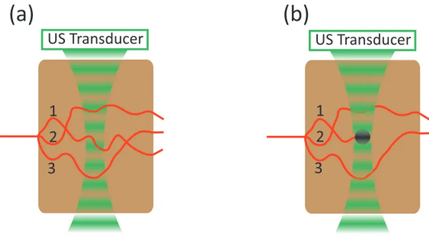
http://rsfs.royalsocietypublishing.org/content/royfocus/1/4/632.full.pdf Copyrighted content.
Original figure can be found at:
Figure 2.2 – Principles of acousto-optic imaging of multiple scattering media. The scattered photons propagating through the sample have the optical path changing due to an acoustic field. Taken from [22]
addition, the acoustic wave makes scatterers vibrate, which results in a modulation of the optical paths, and thus contributes to a modulation of the global phase of the light. Ultrasound and light mixing in a multiple scattering medium is illustrated in Fig. 2.2 (taken from [22]). It shows the effects of the changes of the optical pathlength due to the
vibration of scatterers and the changes of the refractive index. The study and modelling of the acousto-optic interaction in multiple scattering media has only started in the 1990s. The first theories took into account only one of these phenomena, usually the vibration of scatterers. The first model was proposed by Leutz and Maret in 1995 [23], were they considered that the scatterers in a liquid vibrates both because of the Brownian motion and the acoustic field. This model was completed in 1997 by Kempe et al. where they considered the non uniformity of the ultrasonic field [24]. In 2001, L. Wang analytically modelled the phase modulation of the light taking into account both the vibrations of the scatterers and the modulation of the refractive index [25].
In the following, we will consider that photons propagate in straight lines between
scatterers at position rj, as shown in the diagram from Fig. 1.1. The length of the
jth mean free path between scatterers r
j−1 and rj will be called lj and sj will be the
coordinates along this path.
Phase modulation by modulation of the refractive index An acoustic wave is
a periodic modulation of the pressure inside its propagation medium. As a result, the local density of the material changes causing local variations of the refractive index of the medium. Let us consider an acoustic wave described by the following pressure field:
pac(r, t) = Aacsin(kac· r − ωact) (2.2)
where Aac is the amplitude of the acoustic field, ωac its angular frequency and kac the
wave vector. It creates a local change of the refractive index ∆n which causes a phase
shift during the jth mean free path given by:
Φnj(t) =
Z lj
0 k0∆n(rj, sj, θj, t)dsj (2.3)
where θj is the angle between the acoustic wave vector kac and the jth mean free path.
The modulation of the refractive index due to the acoustic field can be written [25]:
∆n = n0ηkacAacsin(kac· rj−1− ωact+ kacsjcos θj) (2.4)
where n0 is the refractive index of the medium at rest, η is linked to the adiabatic
piezoop-tical coefficient of the material ∂n/∂p (≈ 1.4 × 10⁻¹⁰Pa−1in water [26]), the density of
the medium ρ and the acoustic velocity νac by: η = (∂n/∂p)ρνac2 . The phase shift by
modulation of the refractive index is accumulated along each scattering mean free path, consequently the total phase accumulated along the travel through the acoustic field will depend on the value of kacls.
Phase modulation by vibration of scatterers The other phenomenon that
modu-lates the phase of the light propagating through an acoustic field in a multiple scattering medium is the vibration of the scatterers. Indeed, the acoustic wave makes the scatterers vibrate around their rest position; so, when a photon is scattered, its frequency is shifted