HAL Id: inria-00449757
https://hal.inria.fr/inria-00449757
Submitted on 22 Jan 2010HAL is a multi-disciplinary open access archive for the deposit and dissemination of sci-entific research documents, whether they are pub-lished or not. The documents may come from teaching and research institutions in France or abroad, or from public or private research centers.
L’archive ouverte pluridisciplinaire HAL, est destinée au dépôt et à la diffusion de documents scientifiques de niveau recherche, publiés ou non, émanant des établissements d’enseignement et de recherche français ou étrangers, des laboratoires publics ou privés.
Architecture-Driven Synthesis of Reconfigurable Cells
Christophe Wolinski, Krzysztof Kuchcinski, Erwan Raffin, François Charot
To cite this version:
Christophe Wolinski, Krzysztof Kuchcinski, Erwan Raffin, François Charot. Architecture-Driven Syn-thesis of Reconfigurable Cells. 12th Euromicro Conference on Digital System Design, Architectures, Methods and Tools (DSD 2009), Aug 2009, Patras, Greece. pp.531-538. �inria-00449757�
Architecture-Driven Synthesis of Reconfigurable Cells
Christophe Wolinski
University of Rennes I
IRISA, INRIA, France
[email protected]
Krzysztof Kuchcinski
Dept. of Computer Science
Lund University, Sweden
[email protected]
Erwan Raffin
Thomson R&D
Rennes, France
[email protected]
François Charot
INRIA
Rennes, France
[email protected]
Abstract
In this paper, we present a novel method for merging sets of computational patterns into a reconfigurable cell respecting design constraints and optimizing specific design aspects. Each cell can then be used in a run-time recon-figurable processor extension. Our method uses constraint programming to define the pattern merging problem and therefore can easily include design constraints and optimize different design aspects. Experiments carried out on Media-Bench test suite indicate 50% average reduction of cell area without increasing critical path.
1 Introduction
In this paper, we consider an architecture model of an ASIP processor with extended instruction set. Extended in-structions implement identified and selected computational patterns and can be executed sequentially or in parallel with the ASIP core processor instructions [13]. Our generic sim-plified architecture is depicted in Figure 1. It is composed of heterogeneous cells and registers connected by an inter-connection structure with the processor’s data-path. The number of registers and the structure of interconnections are application-dependent. Each cell implements one or more patterns selected by our system [13].
Systematic methods for identification and selection of computational patterns to achieve maximal coverage of a particular application graph were already presented in [11, 12]. We have also presented a new method that con-currently schedules an application and selects patterns to achieve best performance [13]. In this paper, we focus on merging computational patterns to form a corresponding optimized reconfigurable cell. Existing methods cannot control critical paths and placement of multiplexers dur-ing mergdur-ing. This leads to generation of area optimized architectures that often do not satisfy timing constraints. Timing constraints are, however, very important when the clock cycle of an ASIP processor needs to be optimized.
!"#$ !"#% !"#& '()"*+,(("+)-,(. /0)0120)3 4*,+"..,*5+,*" !"+,(!#6*078" +"88 -( 9 -( 9 -( : -( : : 9 9 ,6) ,6) ,6) ,6) 9 -( ,6) 9 -( ,6) -( : -( ,6) : -( ,6) -( ,6) ;5;5; <='4 !"+,(!#6*078" +"88 > >5 ? : -( ,6) : ? -( : -( -(+)*85 @ +)*85$ @ $ @ % $
Figure 1. Generalized ASIP processor model.
Our original approach, based on constraint programming, opens a new perspective and enables area optimization of a cell while respecting design constraints. For instance, area minimization of a merged cell without increasing its critical path is possible in our approach.
The problem of merging computational patterns can be modeled using graphs. When each pattern is defined by a labeled graph, finding a suitable merge can be defined as finding the maximum common sub-graph isomorphism (MCS). This is an optimization problem that is known to be NP-hard. Formally, the problem, defined for two graphs (G1and G2), is to find the largest induced sub-graph of G1
isomorphic to a sub-graph of G2. One possible solution
for this problem is to build a modular product graph [1], in which the largest clique represents a solution for the MCS problem. The other method is to use a kind of backtrack-ing algorithm that iteratively adds vertices which does not violate the common sub-graph condition. Our approach uses the first method and builds first a compatibility graph between two patterns and then finds a clique that maximizes a given cost function. Note, that we are not necessarily looking for a maximal clique (and MCS) but we examine solutions that optimize a particular cost function represent-ing specific features of our reconfigurable unit.
The paper is organized as follows. In section 2 the related work on pattern merging is discussed. Section 3 2009 12th Euromicro Conference on Digital System Design / Architectures, Methods and Tools
!" #$% !& '( )* !+ ', )* !-!. #$% '/ )* )* )*
Figure 2. Set of patterns.
introduces briefly our method and discusses constraint pro-gramming that is used in our approach. Pattern merging is discussed in section 4 that also contains the description of different architectural constraint and merging methods. Section 5 presents experimental results. Finally, conclu-sions are presented in section 6.
2 Related Work
Computational pattern merging has been explored, in first place, in the context of reconfigurable architectures. It can be carried out on fine (circuit or logic) or coarse grain level (functional blocks) but we are interested in this paper on functional reconfiguration that implies coarse grain level only. The patterns for this problem are usually modeled as graphs and graph algorithms can be applied for solving the problem. Sub-graph isomorphism has been, for example, used in [13] for identification and selection of patterns and in [3] for pattern matching and merging. Clique partitioning of compatibility graphs has been used for pattern merging in [9]. In our work, we use constraint programming and graph constraint for sub-graph isomorphism and clique finding. In this framework we can combine optimal and heuristic methods for solving pattern merging problem.
A design flow for a simple processor with a dynam-ically reconfigurable data-path acting as an accelerating co-processor for a specific application domain has been proposed in [6]. The authors reported significant speedup for accelerators that have data-path consisting of hardwired function units and reconfigurable interconnect. Integer Lin-ear Programming (ILP) has been used to solve hardware resource sharing and allocation, and maximum clique find-ing on compatibility graphs for data-path mergfind-ing. Our approach also uses compatibility graphs, but we define different design constraints and cost functions to find the best reconfigurable accelerators. We also use a constraint programming approach that makes it possible to use both heuristic and optimal methods in combination with the newest clique finding constraints [10].
In [2] the authors present an efficient heuristic which
!"#!$ %&' (&)* !+#!, (&)+ %&' -. /0 !* /0 /0 (&)" -1#-2 /0 /0 /0 !"#!, %&' !+ -. /0 !*#!$ /0 /0 -1#-2 /0 345%6/7/03859'63':7; <45%&65(:'=%>
Figure 3. Two cases of a merged pattern.
transforms a set of custom instructions into a single hard-ware data-path. Their method starts with a set of customized instructions modeled as directed acyclic graphs (DAGs) and the goal is to minimize the area, not the sharing of interconnections. Their approach is based on the classic problems of finding the longest common sequence and sub-string of two (or more) sequences. The heuristic produces circuits that are much smaller (up to 85.33%) than those synthesized with ILP approach that do not explore resource sharing.
A high level synthesis for data-path-intensive ASIC de-sign has been proposed in [5]. The authors propose a performance optimization using template mapping. The key of their algorithm is the introduction of the concept of bypassabililty which allows partial graph matching. A template node is said to be bypassable on some input if its output value can be set equal to this input by setting the other inputs to constants without inducing side-effects. We use and extend this concept to handle bypassable expres-sions of a data-path to optimize performance as well as area. Recently, in [4], a pattern-based high-level synthesis for FPGA resource reduction has been proposed. The paper presents a general pattern-based synthesis framework that extracts similar structures in programs. Their approach benefits of advanced pruning techniques that include exten-sively sensitive hashing techniques and characteristic vec-tors to capture similar structures. This is based on notion of graph edit distance. Considering knowledge of previously discovered patterns, the data-path generated at the binding step of the synthesis reduces interconnect costs, but with a latency overhead. We also use pruning techniques but they are incorporated in our constraint programming framework.
3 Background
Our method iteratively merges two computational pat-terns represented by graphs. In each step, a pattern selected from a pattern set and a already partially merged pattern are used to produce a new merged pattern. Compatibility
graphs are created for this purpose for pairs of
computa-tional patterns. The nodes of the compatibility graph are created for shared nodes, shared connections and shared paths with bypassed nodes. Finally, the clique partitioning with a given cost function that optimizes specific design features under architectural constraints is used. The
nov-elty of our approach is twofold. First, it is possible to apply different architectural constraints during the merging process, which was not possible using previous merging approaches and second, it is possible to solve the problem globally and even, in some cases, prove optimality for pairs of computational patterns.
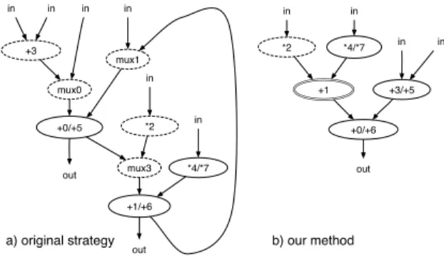
Figure 3 depicts merged patterns obtained using our system for the pattern set from Figure 2. The first pat-tern, depicted in Figure 3.a, was obtained under conditions corresponding to the merging approach presented in [9]. The pattern from Figure 3.b, was obtained under conditions that the length of a critical path is three, the number of multiplexers on the critical path is zero and the bypassed
nodes option is selected. Node “+1” in Figure 3.b is a bypassed node, which only passes data without any
pro-cessing for the second pattern from Figure 2. The quality of the design has been significantly improved by applying additional architectural constraints. Both the area and the critical path are optimized. This simple example shows that the standard approach largely used in the past is not always efficient.
Unlike other approaches our system was built using the constraint programming framework, which makes it pos-sible to combine different constraints and solve the entire problem while maximizing the weighted clique in the
com-patibility graph.
3.1 Constraint programming approach
Our system is implemented using our constraint pro-gramming environment [7] that provides constraint solving methods for finite domain constraints.
Formally, a constraint satisfaction problem is defined as a 3-tuple S = (V,D,C) where V = {x1,x2, . . . ,xn} is
a set of variables, D= {D1,D2, . . . ,Dn} is a set of finite
domains (FD), andC is a set of constraints. Finite domain
variables (FDV) are defined by their domains, i.e. the values that are possible for them. A finite domain is usually expressed using integers, for example x :: 1..7. A constraint
c(x1,x2, . . . ,xn) ∈C among variables ofV is a subset of
D1× D2× ... × Dn that restricts which combinations of
values the variables can simultaneously take. Equations, inequalities and even programs can define a constraint. A
solution to a CSP is an assignment of a value from variable’s
domain to every variable, in such a way that all constraints are satisfied.
The solver is built using constraints own consistency
methods and systematic search procedures. Consistency
methods remove inconsistent values from the domains in
order to reach a set of pruned domains such that their com-binations are valid solutions. Each time a value is removed from a FD, all the constraints that contain that variable are revised. Most consistency techniques are not complete and the solver needs to explore the remaining domains for a solution using search.
Solutions to a CSP are usually found by systematically assigning values from variables domains to the variables, implemented as depth-first-search. The consistency method is called as soon as the domains of the variables for a given constraint are pruned. If a partial solution violates any of the constraints, backtracking will take place, reducing the size of the remaining search space.
Clique finding is known to be a difficult problem and maximal clique finding is known to be NP-hard. In our work, we use a clique constraint,Clique. This constraint takes as an argument a graph and a finite domain variable defining a size of its clique (K). The constraint assures that 0/1 variables assigned to its nodes are one if related nodes belong to a clique and K defines the size of the clique. VariableKcan be used to get a size of a clique, to constrain its size or to find maximal clique by maximizing the value of this variable. The consistency method implemented by theCliqueconstraint is based on algorithms of [10]. That approach has proved to solve many difficult problems as well as, for the first time, solve a number of problems with unknown results. In our experiments we have solved many large graphs rather quickly. For example, a weighted clique is found in a graph with 2,122 nodes and 2,116,470 edges in ∼ 2s.
4 Pattern Merging
The idea of pattern merging briefly sketched in section 3 is implemented in the pattern merging algorithm. The algo-rithm accepts input pattern set and produces a merged
pat-tern. The pattern merging is composed of a pre-processing part and an iterative part. In the pre-processing part, the
reordering function can be applied to the input pattern set for critical path optimization.
During each iteration of the iterative part, the pattern merging method is executed for two patterns: the temporary
merged pattern and the next pattern selected from pattern
set. The merging method is composed of several steps, such as compatibility graph generation, constraint genera-tion for weighted clique problem, constraint generagenera-tion for critical path problem, constraint generation for multiplexer minimization problem and optimization. The optimization step uses our solver [7] and works on compatibility graph and generated constraints. Critical path and multiplexer constraints are only generated when respective options are
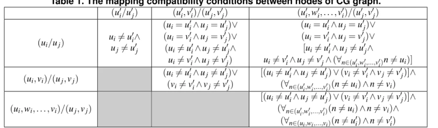
Table 1. The mapping compatibility conditions between nodes of CG graph. (u$ i/u$j) (u$i,v$i)/(u$j,v$j) (u$i,w$i, . . . ,vi$)/(u$j,v$j) (ui/uj) ui%= u $ i∧ uj%= u$j (ui= u$i∧ uj= u$j)∨ (ui= v$i∧ uj= v$j)∨ (ui%= u$i∧ uj%= u$j∧ ui%= v$i∧ uj%= v$j) (ui= u$i∧ uj= u$j)∨ (ui= v$i∧ uj= v$j)∨ [ui%= u$i∧ uj%= u$j∧ ui%= v$i∧ uj%= v$j∧ (∀n∈(u$i,w$i,...,v$i)n %= ui)] (ui,vi)/(uj,vj) (ui%= u $ i∧ uj%= u$j)∨ (vi%= v$i∧ vj%= v$j) [(ui%= u$i∧ uj%= u$j) ∨ (vi%= v$i∧ vj%= v$j)]∧ (∀n∈(u$i,w$i,...,v$i)(n %= ui) ∧ n %= vi) (ui,wi, . . . ,vi)/(uj,vj) [(ui%= u$i∧ uj%= u$j) ∨ (vi%= v$i∧ vj%= v$j)]∧ (∀n∈(u$ i,w$i,...,v$i)(n %= ui) ∧ n %= vi)∧ (∀n∈(ui,wi,...,vi)(n %= u$i) ∧ n %= v$i) selected.
The last step of the iterative part is an update procedure, which is applied to the new pattern set composed of all pat-terns already used in the merging process. This procedure injects into these patterns information about shared nodes and information about multiplexer placement on critical paths. This is carried out when the option on multiplexer limit is selected. 4.1 Compatibility Graph !"#$"% !&'$&( !&'$&) !&*$&( !&*$&) !&+$&( !&+$&) !",$"% !-"#.&*/$-"%.&)/ !-&'.&+/$-&(.&)/ !-&*.&+/$-&(.&)/
!-",.&*/$-"%.&)/ !-"#.&*.&+/$-"%.&)/ !-",.&*.&+/$-"%.!&)/
Figure 4. Compatibility graph and maximal weighted clique for pattern set from Figure 2.
The compatibility graph is undirected graph
CG = (Vc,Ec), where Vcis a set of vertices and Ec⊆ Vc×Vc
is a set of edges. Assuming two pattern graphs, Gi= (Vi,Ei)
and Gj = (Vj,Ej) the compatibility graph contains three
types of nodes:
• regular nodes denoted as ui/uj, where ui∈ Viand uj∈
Vj,
• edge nodes denoted as (ui,vi)/(uj,vj), where
(ui,vi) ∈ Eiand (uj,vj) ∈ Ej, and
• path nodes denoted as (ui,wi, . . . ,vi)/(uj,vj), where
(ui,wi, . . . ,vi) is a simple path in Giwith the sequence
of edges (ui,wi),(wi,pi),...,(qi,vi) and (uj,vj) ∈ Ej.
The regular node is defined for compatible nodes of pattern graphs. Two nodes ui∈ Vi and uj∈ Vj are compatible if
they have the same type and the same number of inputs. Similarly, edge nodes are defined for compatible edges. Edges (ui,vi) and (uj,vj) are compatible if node uiis
com-patible with node ujand node viis compatible with node vj.
Finally, path nodes define compatibility relations between a path and an edge. Path (ui,wi, . . . ,vi) is compatible with
edge (uj,vj) if uiis compatible to uj, viis compatible to vj
and all others nodes on the path can be bypassed.
An edge in CG defines mapping compatibility between two nodes. Mapping compatibly respects a number of con-ditions between these nodes that are specified for all types of nodes in Table 1. For instance, an edge (ui/uj,u$i/u$j)
exists in the CG between two regular CG nodes, ui/uj and
u$
i/u$j, if both nodes are not constructed from the same nodes
of pattern graphs. This removes possibility to map the same nodes of pattern graphs more than once. Similar rules apply to edge and path nodes. An example of a compatibility graph for the two patterns from Figure 2 is presented on Figure 4. It was obtained with the bypassed node option se-lected. The ellipse nodes represent regular nodes, squashed rectangles nodes represent edge nodes and square nodes are used to represent path nodes. Nodes encapsulated with solid lines in the CG graph represent the maximal weighted clique found for the merged pattern from Figure 3.b.
Each node in CG has an associated weight. The weights for regular nodes, edge nodes and path nodes are defined by equations (1-3). Special considerations are applied to weights of path nodes. If all nodes on the path are bypassed without any additional logic the weight is zero.
weight(ui/uj) = Area(u) − Area(Mux) (1)
weight((ui,vi)/(uj,vj)) = Area(Mux) (2)
weight((ui,wi, . . . ,vi)/(uj,vj)) = (3)
Area(Mux) − Area((ui,wi, . . . ,vi))
Area(u) represents the area of node u and Area(Mux)
represents the area of a multiplexer. The weight of a node expresses the area reduction of the merged pat-tern if a given node is selected for merging. For in-stance, if node (ui/uj) is selected the corresponding area
reduction is Area(u)+Area(u)−Area(u)−Area(Mux), as-suming Area(u) = Area(ui) = Area(uj) since two nodes
were replaced with one node and a multiplexer. If ei-ther (ui,vi)/(uj,vj) or (ui,wi, . . . ,vi)/(uj,vj) nodes are
se-lected for merging, the merged pattern area is reduced by Area(Mux) or Area(Mux) − Area((ui,wi, . . . ,vi)
respec-tively because the multiplexer is removed at the end of an edge.
4.2 Weighted Clique Model
To be able to compute a maximal weighted clique of CG graph each node u ∈ Vcis modeled by finite domain variable
Selu= {0,1}. Variable Selu= 1 if the node is a member of
a maximal weighted clique and 0 otherwise. A clique in
CG is defined by constraint (4). This constraint imposes
a condition for each two not connected nodes in the CG graph. At most one of these nodes can have its variable
Selu= 1. In order to find the maximal weighted clique
in CG the Sum variable defined by constraint (5) must be maximized. Each weight(u) is defined by equations (1-3).
∀(uc,vc) /∈ Ec: Seluc%= 1 ∨ Selvc%= 1 (4)
Sum =
∑
u∈Vc
Selu· weight(u) (5)
In practice, we do not use formulation specified in equation (4) but we use ourCliqueconstraint instead. This makes it possible to handle large clique graphs.
4.3 Critical Path Model
The length of the critical path of a pattern can be com-puted off-line but when the merging algorithm uses
by-passed nodes, the size of the critical path can increase. This
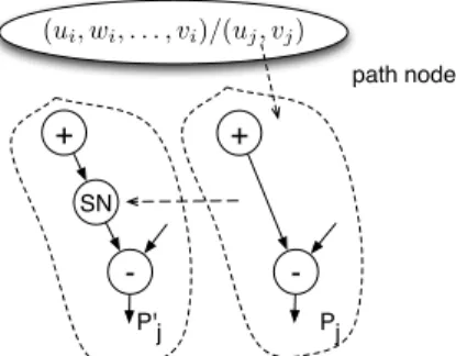
is the case, for example, for the second pattern from Figure 2, where its critical path after the merging was increased by the bypassed node “+1” (see Figure 3.b). To ensure that the length of the critical path does not grow beyond a given value, the length of the pattern’s critical path must be limited during the optimization process. This is achieved by replacing an original pattern by a new pattern. In this new pattern, each edge (uj,vj) ∈ Ej from the path node
is replaced by a path with an additional special node SN. Figure 5 shows the path node and a part of the pattern modified according to this rule. As the result, pattern P$ j
contains the initial Pjregular nodes and special node SN.
Each node u ∈ Vjof pattern P$jis modeled by two finite
domain variables: Startuand Delayu. Variable Delayufor
! "# $ $ ! %&'()*+,-./ .0/
Figure 5. Pattern transformation for critical path optimization.
regular nodes defines the latency of the node (denoted as
Latency(u)). For special nodes DelaySNu= 0 if the
corre-sponding path node is not selected in the maximal weighted clique and it is equal to the latency of the related path in Pi
otherwise (constraint (6)). The data dependencies for P$
jare
imposed by constraint (7). The latency of the critical path is limited by constraint (8) where ONS is a set of output nodes in P$
jand CPL is an imposed critical path latency.
∀u ∈ Vc,u = (ui,wi, . . . ,vi)/(uj,vj) : (6)
DelaySNu= Selu·
∑
n∈{ui,wi,...,vi}
Latency(n)
∀(uj,vj) ∈ E$j: Startuj+ Delayuj≤ Startvj (7)
∀u ∈ ONS : Startu+ Delayu≤ CPL (8)
4.4 Model with Multiplexers
When the compatible nodes originated from two patterns share the same node in the resulting merged pattern, multi-plexers are often added. Figure 6 shows an example of two shared nodes. The first node needs a multiplexer while the second one does not need it since it shares the entire edge.
It may also happen that multiplexers are added on the critical path. For example, this is the case for the merged pattern depicted in Figure 3.a. In order to minimize the latency of the merged patterns, it is necessary to impose an adequate condition on the number of multiplexers on the critical path. We achieve this by introducing additional constraints. First, the critical path latency, CPL, is calcu-lated for all patterns P1, ...,PKalready merged by the pattern
merging algorithm described in section 4. This is defined as follows CPL = Max{Latency(P1),...,Latency(PK)}, where
Latency(Pi) computes the latency of pattern Pi. In the next
step, for each pattern Pi with Latency(Pi) = CPL, a SNCPi
set is generated. This set contains all nodes found on the critical path of pattern Pi. The nodes situated on the critical
Figure 6. Multiplexers insertion after pattern merging. for each ui∈ SNCPi SSNui=/0, SSNu$i=/0 for each u ∈ Vc if u = ui/uj SSNui= SSNui∪ {Selu} if u = (vi,ui)/(uj,vj) ∧ vi∈ SNCPi SSN$ ui= SSNu$i∪ {Selu} if u = (vi,wi, . . . ,ui)/(uj,vj) ∧ vi∈ SNCPi SSN$ ui= SSNu$i∪ {Selu}
Figure 7. Generation algorithm for sets SSNui
and SSN$ ui.
To express conditions on multiplexers, we create sets
SSNui and SSNu$i for each ui∈ SNCPi. These sets contain
Selui variables associated to nodes of compatibility graph
CG and are defined in the algorithm depicted in Figure 7.
If at least one variable from set SSNui has value 1 it means
that the corresponding node in CG has been selected and node uiis shared in the resulting merged pattern. Similarly,
if the value of a variable from set SSN$
ui is 1, it means that
the corresponding node in CG has been selected and the entire edge is merged (the node ui is a destination node in
the merged edge).
Muxui= 1 if T NMui>0 R1 if T NMui= 0 ∧ SSNui%= /0 ∧ SSNu$i=/0 R2 if T NMui= 0 ∧ SSNui%= /0 ∧ SSNu$i%= /0 0 if T NMui= 0 ∧ SSNui=/0 (9) R1⇔
∑
Sel∈SSNui Sel > 0 R2= R1· R, where R ⇔∑
Sel∈SSN$ui Sel = 0Each node ui∈ SNCPj is modeled by two finite domain
variables: Startui and Muxui. The multiplexer variable
Muxui is defined by the constraint (9). The value of this
variable is 1 if the multiplexer is added and 0 otherwise. The
first condition in constraint (9) specifies that a multiplexer already exists. Value T NMui>0 if node uiis already shared
and 0 otherwise. This variable is set in the update step of the iterative part of the pattern merging algorithm described in section 4. The second condition means that there is no multiplexer yet, but it would be needed when R1= 1, since
the node is shared in the merged pattern. The next condition defines a situation when a multiplexer does not exist yet, but it would be needed if R1= 1 and R2= 0. This happens if
node uiis shared and the edge with the destination node ui
is not. The last condition says that there is no multiplexer and none need to be added.
In order to satisfy the condition about the number of mul-tiplexers on the critical path, constraints (10) and (11) are imposed. Constraint (10) takes into account data dependen-cies between the nodes in the SNCPiset. These constraints
make it possible to calculate the number of multiplexers in pattern Picritical path. Constraint (11) bounds the number
of multiplexers. ONS$is a set of output nodes in SNCPiand
MNM is the maximal allowed number of multiplexers on
pattern Picritical paths.
∀ui,vi∈ SNCPi, (ui,vi) ∈ Ei: Startui+ Muxui≤ Startvi
(10)
∀u ∈ ONS$: Startu+ Muxu≤ MNM (11)
5 Experimental Results
We have carried out extensive experiments to evaluate the quality of our method for pattern merging. All ex-periments have been run on 2GHz Intel Core Duo under the Mac OSX operating system. In this paper, we present two classes of examples. The first is an example of EPIC
decoder application coming from [9]. The second
exper-iment has been carried out for different sets of patterns identified by our system for MediaBench test suite of DSP applications [8].
Figure 8. Execution time in ms for pattern merging.
Table 2. Results for the EPIC decoder application [9].
Input Selected Optimizations Compatibility Graph Selected Nodes in Time Merged Pattern Area
Application Patterns Nodes Edges Max. Weighted Clique in Imp.
nodes edges N E P CP NM Reg. Edge Path Reg. Edge Path sec node edge mux in %
EPIC DECODER 1612 1116 Yes Yes 31 15 0 858 10 6 0 1.02 18 30 5 48%
15 13 Yes Yes 49 31 0 2717 15 9 0 0.85
EPIC DECODER 1612 1116 Yes Yes 2 31 15 8 1151 10 6 1 3.71 18 25 3 50%
15 13 Yes Yes 2 49 28 12 3225 15 9 2 1.24
EPIC DECODER 1216 1611 Yes Yes 2 Yes 0 31 15 2 1151 9 6 0 1.18 20 29 4 45%
15 13 Yes Yes 2 Yes 0 49 28 12 3225 13 8 1 2.15
Table 2 gathers the detailed results obtained for three experiments carried out for the EPIC decoder application [9]. These experiments were performed using different optimization options. They illustrate the possibility of our system to carry out design space exploration under syn-thesis constraints. The first experiment corresponds to the original case from [9], where only node and edge sharing options (N and E) are selected. In this case, our system obtains the same results as those presented in [9]. In the second experiment, the path sharing option has been added (P = 2), which alllows a maximum of two bypassed nodes on a path. This reduces the number of multiplexers by 40% and the number of edges by 16%. In the last experiment, the critical path cannot increase (CP=Yes) due to insertion of
bypassed nodes and the number of multiplexers is limited to
two (NM=2) on this path. The resulting merged pattern has only increased by two nodes, one edge and one multiplexer comparing to the second experiment. The system found optimal weighted cliques and proved their optimality.
Table 3 shows different results obtained for the set of patterns identified by our system for DSP applications from the MediaBench test suite [8]. The area reduction is specified in relation to the area of the set of patterns, and it is expressed in the number of combinational atoms (denoted as CA in Table 3) for 32 bits operators. We also specify the number of edges in the merged patterns. For each application from the MediaBench test suite, five experiments with the following options have been carried out (N, E, P, CP and NM are defined as previously).
Exp.1 N=Yes
Exp.2 N=Yes E=Yes P=2
Exp.3 N=Yes E=Yes NM=0
Exp.4 N=Yes E=Yes P=2 CP=Yes NM=0 Exp.5 N=Yes E=Yes P=2 CP=Yes NM=2
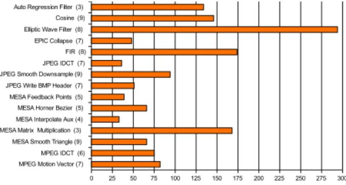
The average area reduction (without interconnect area) for five experiments are 66.5%, 67.67%, 41.07%, 50.47%, 66.6% respectively. All weighted cliques found during pat-tern merging were proved optimal. As an example, Figure 8 shows the execution time for all applications (including the time for the optimality proof) for most restrictive Exp.4 experiment. The average execution time is only 0.1s.
!" #$% !& '( )* !+ )* ', )* !-'. '/ '0 )* #$% '1 )* #$% '&" !&& )* #$% '&( )* )*
Figure 9. Set of patterns for ARF application.
The complete example is presented in figures 9, 10 and 11. It shows the patterns obtained by our system for the auto regression filter (ARF), the merged pattern and the corre-sponding architecture of the reconfigurable ASIP processor respectively. !" #$% !&'!('!&& )* )+ #$% ),')-')&" ./ !0 ./ ./ )1')2')&, ./ #$% #$%
Figure 10. Merged pattern for ARF applica-tion.
6 Conclusions
In this paper we have presented a new approach to synthesis of reconfigurable cells, based on computational pattern merging. An important novelty of our approach lies in the way we combine different design constraints in synthesis. This is achieved by using a constraint program-ming framework that makes it possible to combine clique
Table 3. Pattern merging results for pattern sets identified by our system (MediaBench test suite).
Application patternsNb. Exp. 1 Exp. 2Area reduction in %Exp. 3 Exp. 4 Exp. 5 Exp. 1Area in CA for Altera Stratix2 EP2560Exp. 2 Exp. 3 Exp. 4 Exp. 5 Exp. 1Number of Edges in merged patternExp. 2 Exp. 3 Exp. 4 Exp. 5
Auto Regression Filter 3 47 49 1 48 48 2180 2084 4168 2048 2048 20 14 24 14 14
Cosine 9 81 86 9 10 84 1476 1412 3164 2473 1473 35 36 67 48 44
Elliptic Wave Filter 8 80 80 72 73 78 1442 1442 2067 2003 1600 43 37 54 45 44
EPIC Collapse 7 67 68 13 23 67 1127 1059 2882 2576 1092 38 37 56 48 40
FIR 8 81 82 72 80 80 1378 1250 1971 1410 1378 35 24 41 35 35
JPEG IDCT 7 75 76 56 66 75 1379 1347 2469 1948 1379 36 32 47 42 37
JPEG Smooth Downsample 9 64 64 51 53 66 448 448 608 576 436 36 31 44 39 31
JPEG Write BMP Header 7 73 73 12 12 71 1073 1073 5548 4045 1137 26 26 64 62 32
MESA Feedback Points 5 50 54 38 40 54 1843 1715 2308 2212 1715 33 26 34 28 26
MESA Horner Bezier 5 59 60 35 48 60 1683 1619 2677 2148 1619 19 15 21 17 15
MESA Interpolate Aux 4 23 23 22 23 23 1684 1684 1716 1700 1684 19 19 22 20 19
MESA Matrix Multiplication 3 76 77 55 75 75 2340 2318 4520 2436 2436 35 32 56 41 40
MESA Smooth Triangle 9 78 79 66 66 75 2370 2278 3835 3770 2808 37 30 40 36 33
MPEG IDCT 6 63 63 51 61 63 1810 1804 2390 1861 1804 54 54 66 60 54
MPEG Motion Vector 7 81 81 63 79 80 1218 1218 2340 1314 1282 22 21 33 26 24
Average 66.53 67.67 41.07 50.47 66.6
Figure 11. An example of ASIP processor build around MIPS processor core for ARF application.
finding, based on compatibility graphs, along with other design constraints. With this method we can generate cells that satisfy design constraint and optimize certain required design aspects.
Our experiments show rather high area reductions while generating different alternative merged cells depending on selected design constraints. For MediaBench test suite we have obtained cells that fulfill design constraints and save between 41% and 67% area.
References
[1] U. Brandes and T. Erlebach. Network Analysis: Method-ological Foundations. Springer, 2005.
[2] P. Brisk, A. Kaplan, and M. Sarrafzadeh. Area-efficient instruction set synthesis for reconfigurable system-on-chip designs. Proc. 41st Design Automation Conference, pages 395–400, 2004.
[3] N. Clark, H. Zhong, and S. Mahlke. Automated custom instruction generation for domain-specific processor
accel-eration. IEEE Trans. Comput., 54(10):1258–1270, Oct. 2005.
[4] J. Cong and W. Jiang. Pattern-based behavior synthesis for FPGA resource reduction. In FPGA ’08: Proceedings of the 16th international ACM/SIGDA symposium on Field programmable gate arrays, pages 107–116, New York, NY, USA, 2008. ACM.
[5] M. Corazao, M. Khalaf, L. Guerra, M. Potkonjak, and J. Rabaey. Performance optimization using template map-ping for datapath-intensive high-level synthesis. IEEE Trans. Computer-Aided Design, 15(8):877–888, Aug. 2004. [6] Z. Huang, S. Malik, N. Moreano, and G. Araujo. The design of dynamically reconfigurable datapath coprocessors. ACM Transaction in Embedded Computing Systems, 3(2), May 2004.
[7] K. Kuchcinski. Constraints-driven scheduling and resource assignment. ACM Transactions on Design Automation of Electronic Systems (TODAES), 8(3):355–383, July 2003. [8] C. Lee, M. Potkonjak, and W. H. Mangione-Smith.
Medi-aBench: A tool for evaluating and synthesizing multimedia and communicatons systems. In International Symposium on Microarchitecture, pages 330–335, 1997.
[9] N. Moreano, E. Borin, C. de Souza, and G. Araujo. Efficient datapath merging for partially reconfigurable architectures. IEEE Trans. Computer-Aided Design, 24(7):969–980, July 2005.
[10] J.-C. Régin. Solving the maximum clique problem with constraint programming. In Proc. CPAIOR, 2003.
[11] C. Wolinski and K. Kuchcinski. Computation patterns identification for instruction set extensions implemented as reconfigurable hardware. In The Int. Conf. on Engineering of Reconfigurable Systems and Algorithms, Las Vegas, Nevada, USA, June 25-28, 2007.
[12] C. Wolinski and K. Kuchcinski. Identification of applica-tion specific instrucapplica-tions based on sub-graph isomorphism constraints. In IEEE 18th Intl. Conference on Application-specific Systems, Architectures and Processors, Montréal, Canada, July 8-11, 2007.
[13] C. Wolinski and K. Kuchcinski. Automatic selection of application-specific reconfigurable processor extensions. In Proc. Design Automation and Test in Europe, Munich, Ger-many, Mar. 10-14, 2008.

![Table 2. Results for the EPIC decoder application [9].](https://thumb-eu.123doks.com/thumbv2/123doknet/12503364.340476/8.918.250.817.112.474/table-results-epic-decoder-application.webp)

