HAL Id: tel-01147623
https://tel.archives-ouvertes.fr/tel-01147623
Submitted on 30 Apr 2015HAL is a multi-disciplinary open access
archive for the deposit and dissemination of sci-entific research documents, whether they are pub-lished or not. The documents may come from teaching and research institutions in France or
L’archive ouverte pluridisciplinaire HAL, est destinée au dépôt et à la diffusion de documents scientifiques de niveau recherche, publiés ou non, émanant des établissements d’enseignement et de recherche français ou étrangers, des laboratoires
Han Yan
To cite this version:
Han Yan. Collaboration des équipements du réseau domestique pour une meilleure efficacité én-ergétique globale. Autre [cs.OH]. Université Rennes 1, 2014. Français. �NNT : 2014REN1S122�. �tel-01147623�
THÈSE / UNIVERSITÉ DE RENNES 1
sous le sceau de l’Université Européenne de Bretagne
pour le grade de
DOCTEUR DE L’UNIVERSITÉ DE RENNES 1
Mention : Informatique
Ecole doctorale MATISSE
présentée par
Han YAN
Préparée à l’unité de recherche IRISA (UMR 6074)
Institut de Recherche en Informatique et Systèmes Aléatoires
Smart Devices
Collaboration
for Energy Saving
in Home Networks
Thèse soutenue à Rennes le 19/12/2014
devant le jury composé de :
Ye-Qiong SONG
Professeur, Université de Lorraine / rapporteur Mohamed Yacine GHAMRI DOUDANE Professeur, Université de La Rochelle / rapporteur Stéphane LOHIER
Maître de conférence, Université Paris Est / examinateur
Bernard COUSIN
Professeur, Université de Rennes 1 / directeur de thèse
Cédric GUEGUEN
Maître de conférence, Université de Rennes 1/ examinateur
Jean-Paul VUICHARD
Responsable unité de recherche, Orange Labs / co-directeur de thèse
Je tiens avant tout `a remercier le Professeur Ye-Qiong Song ainsi que le Professeur Mohamed Yacine Ghamri-Doudane d’avoir accept´e d’ˆetre les rapporteurs et membres du jury de ma th`ese. Je remercie ´egalement St´ephane Lohier d’avoir accept´e le rˆole d’examinateur de cette th`ese.
Je tiens `a exprimer ma profonde reconnaissance `a mes encadrants qui ont contribu´e `a ces travaux avec la p´edagogie pr´ecieuse de mon directeur de th`ese Bernard Cousin, mon encadrant de th`ese C´edric Gueguen et mon co-directeur de th`ese et manageur Jean-Paul Vuichard qui depuis le tout d´ebut de ma th`ese m’ont conseill´ee, ´epaul´ee, et soutenue, jusqu’`a l’aboutissement de cette th`ese. Je vous remer-cie tous pour vos corrections et vos commentaires pertinents lors de chaque r´edaction d’article et lors de la r´edaction de ma th`ese. J’ai beaucoup appr´eci´e nos discussions r´eguli`eres sur les travaux de la th`ese ainsi que sur les autres sujets vari´es.
Cette th`ese s’est d´eroul´ee au sein du laboratoire “Smart Access in Digital Home” `a Orange Labs et de l’´equipe “Advanced Technology in NETworking” `a l’Irisa. Je tiens `a remercier g´en´eralement les membres de ces deux ´equipes pour le cadre de travail stimulant et la bonne ambiance. Je remercie particuli`erement Fabrice Fontaine avec qui j’ai collabor´e sur plusieurs d´epˆots de brevet. Je remercie Gil Mardon qui m’as encadr´ee pour que je puisse commencer ma th`ese dans de bonnes conditions. Je salue les membres de l’URD HDMI et HEAD qui m’ont accueillie chaleureusement. J’exprime ´egalement ma sympathie aux membres de l’´equipe ATNET qui m’ont accueilli 3 ans et plusieurs semaines jusqu’`a la fin de ma th`ese.
ma famille, ma belle famille et mes amis de toutes nationalit´es pour leurs soutiens qui m’ont ´enorm´ement encourag´e pour mener `a bien ma th`ese.
Abstract
In recent years, Information and Communications Technology (ICT) has totally changed the people daily life in the Digital Home. Mean-while, not only the amount of CO2 emission of ICT, so called “foot-print”, is increasing without cease, but also the price of electricity is constantly rising. Thus, it is quite important to reduce energy consumption in the home network and home devices for the environ-mental and economic reasons.
In order to cope with this context, the thesis concerns the design, the evaluation, and the implementation of a novel set of mechanisms with the purpose of responding to home network energy consumption prob-lems. We proposed firstly an Overlay Energy Control Network which is formed by the overlay energy control nodes. Each node is connected to one device which forms an overlay control network to coordinate the power states of the device. Then, a testbed for HOme Power Ef-ficiency system (HOPE) is implemented to demonstrate the technical solution for energy control in a real home network environment with several frequently used scenarios. After analyzing user’s way of use of their home network equipment, we propose a power management which controls the devices based on the analysis of the collaborative services. These frequently used collaborative services require different functional blocks in different devices. This model provides the pos-sibility to turn on the right requested functional blocks in the right device at the right moment. Finally, based on the former contribu-tion, the collaborative overlay power management offers several pos-sible tradeoffs between the power consumption and the waiting delay in the home network.
Key words: Home network, collaborative service, overlay network, power management, user behaviors, low power network
R´
esum´
e
Au cours des derni`eres ann´ees, la r´evolution num´erique a continu´e sa progression. Les technologies de l’information et des communica-tions (TIC) ont totalement chang´e la vie quotidienne des gens `a leur domicile (concept de maison num´erique ). Pendant ce temps, non seulement le volume des ´emissions de CO2 produit par les TIC, ce qu’on appelle l’empreinte carbone, est sans cesse en croissance mais elle s’accompagne ´egalement d’une hausse du prix de l’´electricit´e, aug-mentant fortement la part des ´equipements num´eriques dans la bud-get global des m´enages. Ainsi, pour des raisons environnementales et ´economiques, r´eduire la consommation d’´energie dans les nombreux ´equipements du r´eseau domestique est devenu un enjeu majeur. Dans ce contexte, la th`ese porte sur la conception, l’´evaluation et la mise en œuvre d’un ensemble de m´ecanismes dans le but de r´epondre aux probl`emes de consommation d’´energie sur les r´eseaux locaux rassem-blant les ´equipements num´eriques domestiques. Nous proposons un r´eseau de contrˆole qui est form´e par des noeuds de contrˆole de l’´energie plac´es au-dessus du r´eseau traditionnel. Chaque noeud de contrˆole est reli´e `a un dispositif en vue de coordonner les ´etats d’alimentation de l’´equipement domestique associ´e. Un d´emonstrateur pour un syst`eme HOme Power Efficiency (HOPE) a ´egalement ´et´e mis en œuvre. Il d´emontre la faisabilit´e de la solution technique que nous proposons pour le contrˆole de l’´energie dans un r´eseau domestique r´eel avec des sc´enarios r´eels qui sont souvent utilis´ees par utilisateur. Apr`es avoir analys´e le mode d’utilisation des ´equipements du r´eseau domes-tique, nous proposons un syst`eme de gestion d’´energie qui contrˆole ces ´equipements minimisant ainsi que leur consommation. Le syst`eme
est bas´e sur l’analyse des services collaboratifs, chaque service est d´ecoup´e en blocs fonctionnels atomiques, distribu´es dans les diff´erents ´
equipements. Cela permet de g´erer avec plus de pr´ecision les be-soins ´energ´etiques de chaque ´equipement de mani`ere `a n’alimenter que les composants n´ecessaires au service demand´e. Pour conclure ces travaux, nous avons ´egalement cherch´e `a minimiser les impacts de l’´economie d’´energie sur la qualit´e d’exp´erience per¸cue par l’utilisateur (notamment le d´elai d’activation des services). Nous proposons un syst`eme de gestion d’´energie pour des services collaboratifs offrant plusieurs compromis possibles entre la consommation d’´energie et le d´elai d’activation des services dans un r´eseau domestique. Il est compl´et´e par un algorithme d’apprentissage du comportement des utilisateurs domestiques.
Mots cl´es: R´eseau domestique, service collaboratif, r´eseau overlay, syst`eme de gestion d’´energie, comportements des utilisateurs, r´eseau `
Au cours des derni`eres ann´ees, la r´evolution num´erique a continu´e sa progres-sion. Les technologies de l’information et des communications (TIC) ont totale-ment chang´e la vie quotidienne des gens `a leur domicile (concept de maison num´erique ). Pendant ce temps, non seulement le volume des ´emissions de CO2 produit par les TIC, ce qu’on appelle l’empreinte carbone, est sans cesse en croissance mais elle s’accompagne ´egalement d’une hausse du prix de l’´electricit´e, augmentant fortement la part des ´equipements num´eriques dans la budget global des m´enages. Ainsi, pour des raisons environnementales et ´economiques, r´eduire la consommation d’´energie dans les nombreux ´equipements du r´eseau domestique est devenu un enjeu majeur.
Probl`
emes ´
etudi´
es
Maison num´erique est appel´e grˆace ”num´erique” pour les dispositifs qui peuvent ˆetre connect´es par diff´erentes technologies de communication. Les ´equipements connect´es peuvent ˆetre une passerelle domestique, un Set-Top Box, un ordinateur personnel, une tablette, ou capteurs de maison, etc. Dans cette section, nous allons pr´esenter les principaux probl`emes que nous avons ´etudi´es dans cette th`ese. Les connectivit´es dans la maison deviennent omnipr´esentes. ˆEtre connect´e est devenu un caract`ere important pour les ´equipements de la maison. Ils ont besoin de fournir divers services pour les utilisateurs du r´eseau de la maison, comme les achats en ligne, le partage multim´edia, vid´eoconf´erence, etc. Technologies de connexion comme le WiFi, Ethernet, Courant Porteur en Ligne sont n´ecessaires pour fournir un r´eseau pratique et de confort pour l’utilisation du service. Bien que parfois les ´equipements connect´es ne sont pas toujours en cours d’utilisation,
Le WiFi, Ethernet ou les communications Courant Porteur en Ligne (CPL) sont maintenus afin de pr´eserver un r´eseau toujours actif `a l’exigence de l’utilisateur. Pour faire partie du r´eseau, des dispositifs tels que la passerelle domestique, ou des plugs CPL sont toujours tous les jours allum´ees afin d’assurer un r´eseau tou-jours actif. Et ce n’est pas n´ecessaire. Par exemple, si il n’y a pas d’´equipement se connecte aux plugs CPL , il n’est donc pas n´ecessaire de garder ce lien tou-jours allum´ee juste pour l’maintenance du r´eseau. On pourrait r´esumer que les connexions r´eseau a la maison ne sont pas utilis´es de mani`ere efficace de l’´energie. Comme mentionn´e pr´ec´edemment, avec la connexion ominipr´esente du r´eseau, les dispositifs ne travaillent plus individuellement. Ils travaillent ensemble pour fournir un service collaboratif. Le service collaboratif plus simple pourrait ˆetre `a t´el´echarger un fichier sur un ordinateur portable. Ce service n´ecessite la passerelle domestique fournit la connexion WiFi pour ´etablir la connexion r´eseau d’ordinateur portable afin de effectuer le t´el´echargement. Dans cet exemple, nous avons au moins deux dispositifs fonctionnent ensemble pour le service collaboratif de t´el´echargement. Si nous prenons un cas d’utilisation plus complexe: UPnP au-dio vid´eo. L’utilisateur contrˆole les ´equipements de la maison avec un point de contrˆole UPnP (smart-phone, iPad ou autre tablette). Il veut regarder un film sur son UPnP multim´edia render (STB). Ce film est enregistr´e sur son serveur de m´edias (PC). Pour effectuer le service UPnP audio video, il est neccesaire d’avoir smart-phone, STB et PC qui collaborent ensemble. Ceci est un autre service collaboratif qui nous montre qu’il est int´eressant de trouver la relation entre les dispositifs.
Un autre probl`eme est les ´equipements connect´es ne sont pas utilis´es de mani`ere efficace en terme d’´energie. Dans la plupart de famille, la Set-Top Box et la t´el´evision sont de plus en plus indispensable. L’´etude de NRDC montre que deux-tiers de l’´electricit´e consomm´ee par les Set-Top Box et la t´el´evision est utilis´e quand ils sont inactifs [16]. Alors que les ´equipements sont en ´etat d’inactifs, cela signifie que les ´equipements ne sont pas n´ecessaires par les services. Bien qu’il est certain que l’´energie consomm´ee dans l’´etat d’inactif est un gaspillage d’´energie r´eel, les utilisateurs ne se passent pas toujours de leurs ´equipements. Il y a deux raisons: d’abord, pas chaque utilisateur a la conscience d’´economiser de l’´energie. Et aussi il y a des utilisateurs qui veulent pas ´eteindre leurs ´equipements, car
ils doivent attendre pendant le temps de d´emarrage tandis que ils ont besoin pour profiter imm´ediatement du service. Ainsi, les ´equipements consomment de l’´energie inutilement alors qu’ils ne sont pas utilis´es.
L’utilisateur joue un rˆole important dans l’environnement de r´eseau domes-tique, parce que les services de r´eseau domestique sont utilis´es par l’utilisateur et la qualit´e de l’exp´erience utilisateur peut directement impacts les choix si l’utilisateur continuera `a utiliser ce service. Il est important de fournir un envi-ronnement de r´eseau domestique plus efficace en ´energie pour les utilisateurs sans affecter l’exp´erience utilisateur. Concr`etement, le comportement de l’utilisateur est la mani`ere dont l’utilisateur se sert de ses ´equipements, `a quel moment, dans quelle occasion etc. Ceci est une information importante pour la maˆıtrise de l’´energie de l’´equipement. Ainsi, la maˆıtrise de l’´energie devrait utiliser cette in-formation pour devenir plus souple et transparente pour l’utilisateur sans changer leur comportement quotidien. Pour la plupart des utilisateurs, ils choisiront d’utiliser la gestion d’alimentation seulement dans le cas o`u leur exp´erience ne sera pas affect´ee par la gestion de la maˆıtrise de l’´energie mis en œuvre.
Contributions
Dans ce contexte, la th`ese porte sur la conception, l’´evaluation et la mise en œuvre d’un ensemble de m´ecanismes dans le but de r´epondre aux probl`emes de consommation d’´energie sur les r´eseaux locaux rassemblant les ´equipements num´eriques domestiques.
Nous proposons tout `a bord un r´eseau de contrˆole (Overlay Energy Control Network: OECN) qui est form´e par des nœuds de contrˆole de l’´energie plac´es au-dessus du r´eseau traditionnel. Chaque nœud de contrˆole est reli´e `a un dis-positif en vue de coordonner les ´etats d’alimentation de l’´equipement domestique associ´e. Avec notre solution propos´ee , les ´equipements peuvent changer de l’´etat d’inactive `a l’´etat veille profond beaucoup plus rapidement et de l’´etat d’inactive `a l’´etat soft-off automatiquement. Le OECN peut ˆetre adaptatif `a nos ´equipements de r´eseau domestique et il est d´evelopp´e de deux fa¸cons:
la maison sont des nœuds ZigBee. Ceci est une ZigBee obligatoire Solution OECN (ZMS).
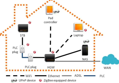
2. Un ou plusieurs dispositifs deviennent les nœuds de contrˆole de l’´energie o`u il n’y a pas de modules ZigBee sur ce dispositif. Ceci est une option ZigBee Solution OECN (ZOS).
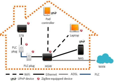
Ces deux fa¸cons de d´eploiement sont illustr´ee dans la Figure 1et la Figure 2.
Figure 1: ZigBee Mandatory energy-saving Solution
Ces deux propositions: ZMS et ZOS, bas´es sur le r´eseau de contrˆole vise `
a r´eduire la consommation d’´energie des ´equipements de r´eseau domestique. Notre simulations prouvent que deux solutions sont efficace tous les deux pour l’´economie de l’´energie. Le ZMS, qui est bas´e sur un OECN complet, est encore plus efficace en termes d’´economies d’´energie par rapport ZOS, mais il a un d´elai relativement ´elev´e par rapport `a le ZOS. Le ZOS, qui est bas´e sur un OECN partielle, est un bon compromis entre le gain d’´energie et le d´elai. Le ZOS a en mˆeme efficacit´e ´energ´etique de temps et peu de retard.
Figure 3: L’architecture HOme Power Efficiency System
Cette conception est mise en oeuvre dans un d´emonstrateur pour un syst`eme Home Power Efficiency (HOPE). Il d´emontre la faisabilit´e de la solution technique que nous proposons pour le contrˆole de l’´energie dans un r´eseau domestique r´eel avec des sc´enarios r´eels qui sont souvent utilis´ees par utilisateur. Syst`eme HOPE allume que les ´equipements dans le but d’´etablir le service `a l’aide d’un r´eseau de contrˆole de faible consommation, illustr´ee dans la Figure 3. A la fin des ser-vices, le HOPE syst`eme v´erifie la possibilit´e de d´esactiver les ´equipements afin d’´eviter la consommation inutile d’´energie. Le d´emonstrateur mis en œuvre mon-tre que le syst`eme HOPE pourrait r´eduire significativement la consommation de
r´eseaux domestiques. Les utilisateurs peuvent b´en´eficier des services multim´edia enrichissant et g´erer efficacement leur consommation d’´energie. En mettant en œuvre le d´emonstrateur sur les cas d’utilisation, nous avons r´ealis´e que de plus en plus de services demandent plusieurs ´equipements diff´erents `a collaborer ensem-ble. Nous avons ´egalement r´ealis´e que les diff´erents blocs fonctionnels collaborent dans les dispositifs pour fournir le services. Nous avons d´ecid´e d’´etudier sur l’´economie d’´energie des services collaboratifs.
Apr`es avoir analys´e le mode d’utilisation des ´equipements du r´eseau domes-tique, nous proposons un syst`eme de gestion d’´energie qui contrˆole ces ´equipements minimisant ainsi que leur consommation. Le syst`eme est bas´e sur l’analyse des services collaboratifs, chaque service est d´ecoup´e en blocs fonctionnels atomiques, distribu´es dans les diff´erents ´equipements. Cela permet de g´erer avec plus de pr´ecision les besoins ´energ´etiques de chaque ´equipement de mani`ere `a n’alimenter que les composants n´ecessaires au service demand´e. Pour conclure ces travaux, nous avons ´egalement cherch´e `a minimiser les impacts de l’´economie d’´energie sur la qualit´e d’exp´erience per¸cue par l’utilisateur (notamment le d´elai d’activation des services). Nous proposons un syst`eme de gestion d’´energie pour des ser-vices collaboratifs offrant plusieurs compromis possibles entre la consommation d’´energie et le d´elai d’activation des services dans un r´eseau domestique. Il est compl´et´e par un algorithme d’apprentissage du comportement des utilisateurs domestiques. Grˆace `a ces travaux, nos solutions atteindre en mˆeme temps une tr`es bonne efficacit´e ´energ´etique et un faible d´elai d’attente de la demande de l’utilisateur.
Remerciements i
Abstract iii
R´esum´e v
R´esum´e de la th`ese en Fran¸cais vii
Contents xiii
List of Figures xvii
List of Tables xxi
List of Abbreviations xxiii
1 Introduction 1
1.1 The context and motivations . . . 1
1.2 Problems studied in this thesis . . . 4
1.3 Main contributions . . . 7
1.4 Thesis outline . . . 8
2 Evolution toward green home network environment 11 2.1 Introduction . . . 12
2.2 Understand the home network environment . . . 12
2.3 Wired and wireless network technologies . . . 14
2.3.2 IEEE 1905.1 . . . 15
2.4 Low power technologies . . . 17
2.4.1 Bluetooth Low Energy . . . 17
2.4.2 ZigBee and IEEE 802.15.4 . . . 18
2.4.3 6LoWPAN . . . 20
2.5 UPnP protocol . . . 21
2.5.1 UPnP Audio Video . . . 23
2.5.2 UPnP Low Power . . . 25
2.5.3 UPnP Energy Management . . . 25
2.6 Conclusion . . . 26
3 Existing power management solutions 27 3.1 Introduction . . . 28
3.2 Device level power management . . . 28
3.2.1 Advanced configuration and power interfaces . . . 28
3.2.2 Dynamic Power management . . . 29
3.2.3 Device element energy reduction . . . 30
3.3 The network level proposed solutions . . . 32
3.3.1 Home Automation Energy Management . . . 32
3.3.2 Network connection power control . . . 33
3.3.3 Home connected devices power consumption management . 34 3.4 Conclusion . . . 35
4 An Overlay Network for energy control 37 4.1 Introduction . . . 38
4.2 The proposed Overlay Energy Control Network . . . 39
4.2.1 Overlay Energy Control Network system . . . 39
4.2.2 Proposed solutions based on Overlay Energy Control Net-work system . . . 42
4.3 Simulation and analysis of results . . . 44
4.3.1 Simulation methodology . . . 44
4.3.2 Simulation of one device analysis of results . . . 53
4.4 Conclusion . . . 62
5 A testbed for HOme Power Efficiency System for a Green Net-work 63 5.1 Introduction . . . 63
5.2 The testbed of HOme Power Efficiency system . . . 64
5.2.1 The architecture of HOme Power Efficiency System . . . . 64
5.2.2 The procedure of HOme Power Efficiency system . . . 67
5.3 Implementation of the HOme Power Efficiency System . . . 70
5.3.1 The software of HOme Power Efficiency system . . . 70
5.3.2 Use cases shown in the home network . . . 72
5.4 Conclusion . . . 75
6 Collaborative power management 77 6.1 Introduction . . . 77
6.2 Architecture of the collaborative power management . . . 78
6.2.1 Power management . . . 78
6.2.2 Home network connected devices . . . 80
6.2.3 Low energy communication overlay network . . . 81
6.3 Energy and delay models . . . 81
6.4 Conclusion . . . 83
7 Collaborative power management with refined overlay algorithms 85 7.1 Introduction . . . 86
7.2 Refined Overlay Power Management & Refined Overlay Auto-Learning Power management . . . 87
7.3 Power Management Modeling . . . 88
7.3.1 User control power management . . . 88
7.3.2 PCE power management . . . 89
7.3.3 ROPM & ROAL power management . . . 90
7.4 Setup of Simulations and Analysis of Results . . . 92
7.4.1 Setup of simulations . . . 92
7.4.2 Analysis of results . . . 93
8 Collaborative power management with delay-power tradeoffs 103
8.1 Introduction . . . 103
8.2 Proposed collaborative overlay power management power-delay trade-off algorithm . . . 104
8.3 Setup of simulations and analysis of results . . . 106
8.3.1 Simulation setup . . . 106
8.3.2 Simulation Results . . . 108
8.4 Conclusion . . . 112
9 Conclusions and Future Perspective 115 9.1 Conclusion . . . 115
9.1.1 The challenges of the complex home network environment 116 9.1.2 Our responses to the challenges . . . 116
9.2 Perspective . . . 118 Appendix A - Patent1261565: Economiser l’´energie du r´eseau
do-mestique tout en maintenant la QoE de l’utilisateur 121 Appendix B - Patent1352881: Syst`eme de gestion intelligente de
la consommation `a haut niveau de granularit´e en analysant des
services collaboratifs 127
Appendix C - Patent1359446: M´ecanisme de gestion intelligente et transparente des connexions r´eseau IPv4/IPv6 par l’interm´ediaire
d’un r´eseau en overlay 6loWPAN 133
Personal publications 139
1 ZigBee Mandatory energy-saving Solution . . . x
2 ZigBee Optional energy-saving Solution . . . x
3 L’architecture HOme Power Efficiency System . . . xi
1.1 Global energy footprint of information and communication tech-nologies . . . 2
1.2 Global energy consumption in France from 1970 to 2010 . . . 3
1.3 French energy residential consumption . . . 4
2.1 OSI model including 1905.1 . . . 16
2.2 Three ZigBee topologies . . . 19
2.3 6LoWPAN Protocol stack . . . 21
2.4 UPnP operation phases . . . 22
2.5 UPnP Audio Video architecture . . . 24
3.1 Power states defined by the ACPI for a personal computer . . . . 28
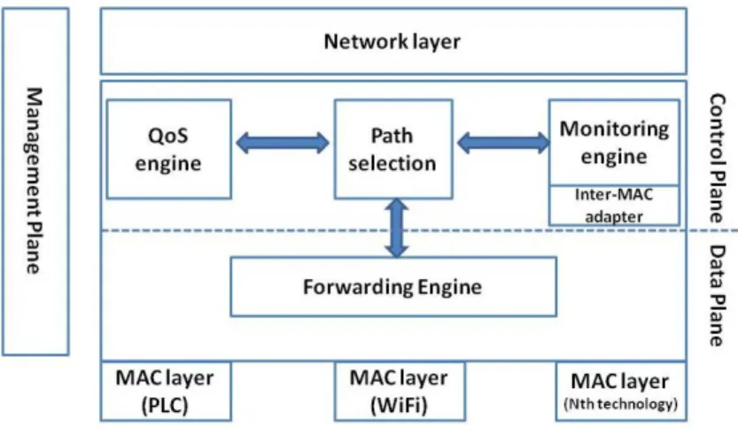
3.2 Network-level inter-MAC architecture . . . 33
4.1 OECN Management . . . 40
4.2 OECN Protocol Stack . . . 42
4.3 ZigBee Mandatory energy-saving Solution . . . 43
4.4 ZigBee Optional energy-saving Solution . . . 44
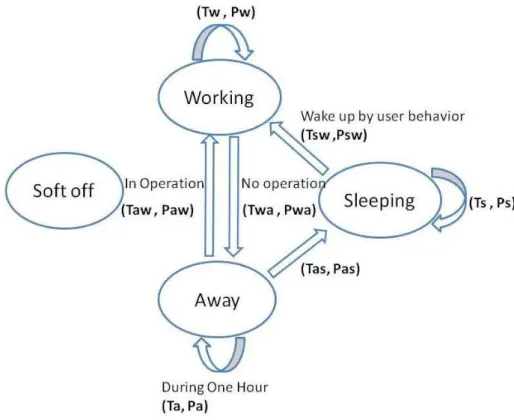
4.5 Device model from the user’s perspective . . . 46
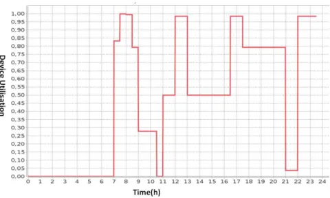
4.6 Set-top Box utilization ratio on working day . . . 48
4.7 Self-controlled Energy Saving Solution . . . 50
4.9 ZigBee Optional Energy Saving Solution . . . 52
4.10 3 energy saving solutions apply on Laptop during Weekend . . . . 54
4.11 3 energy saving solutions apply on Laptop during Wednesday . . 56
4.12 Home network total energy consumption result . . . 59
4.13 Home network energy consumption result . . . 59
4.14 Home network delay result . . . 60
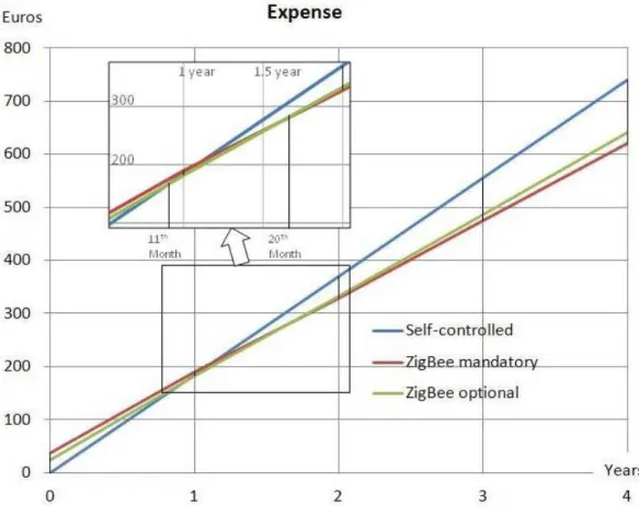
4.15 Home network cost result . . . 61
5.1 Home network environment . . . 65
5.2 Architecture of HOme Power Efficiency System . . . 66
5.3 The procedure of the HOme Power Efficiency System . . . 67
5.4 The algorithm of the HOme Power Efficiency system . . . 68
5.5 The exchanged messages of the IPTV service . . . 69
5.6 The software components of HOme Power Efficiency System . . . 70
5.7 The testbed of the HOme Power Energy system . . . 72
6.1 Collaborative home network service management . . . 78
6.2 A service pattern example . . . 80
6.3 Functional block is turned on (a) in advance (b) by the service request . . . 81
7.1 A service pattern example . . . 89
7.2 ROAL progress the user habits knowledge by increasing the simu-lation time . . . 94
7.3 Energy consumption per service by increasing simulation duration 95 7.4 Delay per service by increasing simulation duration . . . 96
7.5 Energy consumption while changing request time . . . 98
7.6 Delay while changing request time . . . 99
7.7 Energy consumption when standard deviation is changed . . . 101
7.8 Delay when standard deviation is changed . . . 102
8.1 Algorithm of COPM-PDT . . . 105
8.2 Energy while varying the request of Functional Block(FB) . . . . 109
8.3 Delay while varying the request of Functional Block(FB) . . . 110 8.4 Energy consumption and delay while the request at 1000 seconds 110
8.5 Energy consumption while varying the request of tradeoff coefficient111 8.6 Delay while varying the request of tradeoff coefficient . . . 112 1 Architecture d’un r´eseau domestique avec son power management 124 2 Comparaison des consommations avec ou sans la solution propos´ee 125 3 Architecture d’un r´eseau domestique avec son power management 129 4 Apprentissage (Processus d’apprentissage) . . . 130 5 Apprentissage (Processus d’exploration) . . . 131 6 Relation entre ´equipements DLNA avec un Media Server . . . 134 7 Diagramme de s´equence de gestion de la mise en veille
4.1 Home network devices power consumption . . . 47 4.2 An overlay network for energy control notation summary . . . 49 4.3 Device transition time (inactive to active) . . . 57 4.4 Expense on electricity and ZigBee module . . . 57 5.1 Power consumption (Watt hour), Service Time: ST (hours) and
Number of startups parameters of our testbed devices . . . 75 6.1 Collaboration power management notation summary . . . 82 7.1 Refined overlay algorithms simulation setup . . . 93 8.1 Delay-power tradeoffs algorithm simulation setup . . . 107 8.2 Delay-power tradeoffs algorithm simulation energy and waiting
6LoWPAN IPv6 over Low power Wireless Personal Area Networks ACPI Advanced Configuration and Power Interface
BLE Bluetooth Low Energy
CMOS Complementary Metal–Oxide–Semiconductor COPM Collaborative Overlay Power Management
DELS Dynamic Ethernet Link Shutdown DHCP Dynamic Host Configuration Protocol DLNA Digital Living Network Alliance
EMD Energy Monitoring Device FFD Full Function Device HGW Home GateWay
HDD Hard Disk Driver
HOPE HOme Power Efficiency System
IEEE Institute of Electrical and Electronics Engineers HTTP Hypertext Transfer Protocol
IoT Internet of Things IP Internet Protocol LAN Local Area Network MAC Media Access Control MoCA Multimedia over CoAx
OECN Overlay Energy Control Network PAN Personal Area Network
PC Personal Computer PDT Power Delay Tradeoff PCE Power Control Element
PLL Phase-locked loop
PLC Power Line Communication RFD Reduced Function Device
ROPM Refined Overlay Power Management
ROAL Refined Overlay Auto-Learning Power management SHEMS Smart Home Energy Management System
SIG Special Interest Group
SOAP Simple Object Access protocol SSDP Simple Service Discovery Protocol
STB Set-Top Box TV Television
UPnP Universal Plug and Play
UPnP AV Universal Plug and Play Audio Video WAN Wide Area Network
WSN Wireless Sensor Network XML Extensible Markup Language
ZMS ZigBee Mandatory energy saving Solution ZOS ZigBee Optional energy saving Solution
Introduction
Contents
1.1 The context and motivations . . . 1
1.2 Problems studied in this thesis . . . 4
1.3 Main contributions . . . 7
1.4 Thesis outline . . . 8
1.1
The context and motivations
In recent years, Information and Communications Technology (ICT) has totally changed the people daily life. ICT services provide facilities for multimedia, com-munications, entertainment and so on. Meanwhile, the amount of CO2 emission
of ICT, so called “carbon footprint”[91], is increasing without cease. Technol-ogy analysts estimate that ICT represents around 2% of global emissions of CO2
[33]. This amount of carbon emission is the same as aviation industry. However, with rising demand for communication services, devices become more and more powerful. It is also estimated that ICT global emissions could increase to 3% of global emission by 2020 [70]. If nothing is done, the ICT contribution to global greenhouse gas emissions is projected to nearly double to about 4% by 2020. [32] Although there are many reasons that cause the climate change, for example the solar radiation and volcanic activity. However, that human activities are one
of the main causes of climate change. This man made CO2 generation is the
main cause of the global warming which is already becoming a severe issue. As we continue to increase the amount of CO2 in the atmosphere, the warming effect
of this gas is continuing to increase [82]. And the rate of this increase is becoming more and more rapidly according to the IPCC report 2013 [45]. This landmark
Figure 1.1: Global energy footprint of information and communication technologies [45] report by the United Nations climate panel details the physical evidence behind climate change in different scenarios. These scenarios are ranging from “business as usual/no actions taken” to “aggressive actions taken”. In Figure 1.1, we could see based on the scenario RCP 8.5, “business as usual/no actions taken”, average global surface temperatures will likely rise by an additional 1.1 to 4.8 degrees by 2100. This temperature increase is largely above the 1986-2005 average. And this temperature change will be accompanied by other environmental changes such as an increase in global sea level by up to 1–2 feet [45].
It means that the impact is affecting all the continents [22]. For example, in Europe it is estimated that will be multiple stresses and systemic failures due to climate change in the Mediterranean. This will increase energy costs and damage tourism from 2050. And the result, now as then, is a vicious circle of energy consumption and greenhouse gas emissions.
Accordingly, reducing global greenhouse gas emissions and reducing the global energy consumption have become a crucial issue for protecting our earth. In
Figure 1.2: Global energy consumption in France from 1970 to 2010 [83]
order to better reduce the global energy consumption, Figure 1.2 helps us to better understand how the global energy is consumed [83]. We could see from this figure, the energy is shared by residential, transportation, industrial, steel and agriculture sectors. Since 1973 in France, the global energy consumption is increasing with a rhythm at 3 % every year. The residential electricity has become the principal energy consumption section since 1980. The residential tertiary service consumption in France has been multiplied five times which means an increase of more than 4% each year [83].
While we try to zoom in the energy consumption in the residential sector, which means the home environment, we could see from left side of Figure 1.3 the power consumption is mainly composed by the heating, hot water and other specific devices [17].
The energy consumption of the specific devices is composed by the lighting, washing and the multimedia usages shown in right side of Figure1.3. It is impor-tant to note that the multimedia devices are the specific devices which consume a great part of energy at home [14]. There are two main reasons for the energy consumption of the multimedia devices is increasing: there are more and more energy is consumed on the audio video devices for more and more entertainment usages. And the personal computer is no more one computer, the peripherals like
home gateway, printer and so on spread rapidly in our home.
Figure 1.3: Left side: French residential energy consumption Right side: French other specific device energy consumption [14], [17]
Not only the consumption of energy is increasing, but the price of electricity is constantly rising. According to the Vaasa ETT report [15], in 2012 European residential electricity prices increase 2% faster than inflation. Residential energy prices endure a continuous upward trend since the beginning of 2010. The energy consumption is not negligible at all for families [24]. Even for several families, this dispense is becoming harder and harder to pay at the end of each month. Thus, it is quite important to reduce energy consumption in the home network and home devices for the environmental and economic reasons.
In this section, we firstly analyzed the climate change by the ICT sector, then we discuss in details the ICT energy consumption by zooming into the most rapidly increasing part: home environment. The problems that we study in the home environment will be presented in the next section.
1.2
Problems studied in this thesis
Digital Home is called “digital” thanks to the devices which may be connected by different communication technologies. The connected devices could be an home gateway, a Set-Top Box, a Personal Computer, a tablet, or home sensors, etc.. In this section, we will present the main problems that we studied in this thesis.
Network connectivity becomes ubiquitous. Being network-enabled is becom-ing an important feature for home devices. They need to provide various services, like on-line technology, multimedia sharing, video conference, etc., to home net-work users. Netnet-work connection technologies like WiFi, Ethernet, Power Line Communication are required for providing a comfort network for the service use. Although sometimes the connected devices are not in use, the WiFi, Ethernet or Power Line communication connections are maintained to keep an always active network to the user requirement. To be part of the network, devices such as a home gateway, or PLC plugs are always on all days in order to assure an always-on network which may not necessary. For example, if there is no device calways-onnects to the Power line communication plug, it is not necessary to keep this plug always on just for maintaining the network. We could sum up that the home network connections are not used in an energy efficient way.
As mentioned before, with the “Everywhere” network connection, devices work no more alone. They always work together to provide a collaborative service. The simplest collaborative service could be to download a file by laptop, this requires the home gateway provides the WiFi connection for the laptop and laptop launch the download. In this example, we have at least two devices work together for the collaborative download service. If we take a more complex UPnP audio video use case, the user controls the home devices with an UPnP Control Point (smart-phone, iPad or other tablet) and wants to watch a film on his UPnP Media Renderer (STB). This film is saved on his UPnP Media Server (PC). This is another collaborative service which shows us that it is interesting to find the relationship among the devices. It helps us to better control the right device at the right moment in a collaborative service. Moreover, the types of devices in the home network are various: for example, Personal Computer, Home GateWay, Set-Top Box and so on. In order to provide a collaborative service, all these different devices have different functionalities, characteristics which power control should be adapted to. In summary, the home network power control is no more a simple control on only one device, we should consider the home network collaborative services are provided by several devices.
In addition, devices are not turned on in an energy efficient way. Connected device, like laptop, can serve multiple services. In different services, different
functional blocks are used in one laptop depend on the services. For example it may be used on the web surfing by WiFi or it may be used to share a file with another device by Bluetooth. Despite the request service, the connected devices are always turned on integrally. In this home network environment, numerous home devices are widely used and also integrally turned on to contribute to the different home network collaborative service. But these appliances are requested partially in different service requirements.
Another problem is the connected devices are not used in an energy efficient way. In most family, the Set-Top Box and television are becoming indispensable. The study from NRDC shows that two-third of the electricity consumed by Set-Top Box and TVs is consumed when they are idle [16]. While the devices are in idle state, it means that the devices are not needed by services. Although it is for sure that the energy consumed in the idle state is a real energy waste, users do not always turn off their devices. There is two reasons: First, not every user has the energy conscience. And also users do not turn off their devices, because they need to wait during the booting time while they need to enjoy the service immediately. Thus, devices consume unnecessary energy while they are not used. User plays an important role in the home network environment, because the home network services are used by user and the quality of user experience directly impacts if the user will continue to use this service. It is important to provide a more energy efficient home network environment for users without impacting the user experience by studying their behaviors. Concretely, User behavior is the way how the user uses their devices, at what time, in what occasion etc. This is an important information for the device energy control. Thus, the energy control should use this information to become more adaptive and transparent for the user without changing their quotidian behavior. For most of the users, they will choose to use power management only in case that their experience will not be impacted by the implemented energy control management.
In this section, we details the problems that we studied on the network, service, device and user levels. Based on the problems we present in this section, the next main contribution section will be a brief response to the problems.
1.3
Main contributions
This thesis contributes to the control of device energy consumption in a home network. We propose a novel set of power control mechanisms for the current and future home network connections, devices and services in order to respond the home network energy consumption problems.
In order to be reactive for the home network user and energy efficient at the same time, we proposed an Overlay Energy Control Network (OECN) [98] which is formed by the overlay energy control nodes connected to home network device. In this contribution, two solutions, ZigBee Mandatory energy saving Solution (ZMS) and ZigBee Optional energy saving Solution (ZOS) are proposed by considering the different characteristics of different devices. Moreover, devices are turned off instead of staying in idle state after each utilization.
A testbed for HOme Power Efficiency system (HOPE) is implemented to demonstrate the technical solution for energy [93]. The HOPE solution uses an overlay control network which switches existing devices on or off according to their usage. This solution aims to be adaptive for the home network services which requires the collaboration of several devices.
Since the user plays an important role in the home network environment, we studied user’s way of use of their equipment which occurs frequently. This information helps the power management to anticipate the user service request, make decision in advance to turn on the devices, this reduces the waiting delay for user. Meanwhile, we did an analysis on the service request which are collaborative service. We noticed that not the integral devices are required in the collaborative services. We control the devices based on the analysis of the collaborative services. Our control requires different functional blocks in different devices [96]. This model helps users to achieve more efficient energy consumption management [92]. We also registered a patent on this model which take into account the energy consumption and user experience [99].
For sure that when we turn off an electric element, the energy consumption will be decreased. However, this energy gain is often paid by the waiting delay for the user. Based on the former contribution, this collaborative overlay power management that offers several possible tradeoffs between the power consumption
and the waiting delay in the home network. Achieving the minimum waiting delay or the maximum energy efficiency would depend on the user exigencies [97].
Since network connections are always maintained although they are not used. For the purpose of network connection saving, we also proposed a patent to alternate the traffic between a traditional network interface and a low power consumption network interface [94]. When the traffic requires high debit, we use the traditional high power network interface, otherwise we maintain the low power network interface to be reactive for all connected devices.
In this section, we present the main contributions in this thesis. These contri-butions give the propositions to the energy consumption problems on the device, service, network level for the aim of providing a comfortable and energy efficient home network environment for the users.
1.4
Thesis outline
The thesis is divided into 8 chapters. Let’s have a quick view of the content of this work:
Chapter1gives the introduction of our thesis. This chapter will give a presen-tation on the background and motivations of our thesis and the studied problems and main contributions in this context.
Chapter 2 presents evolution toward green home network environment. In this chapter, besides the typical home network connection, we will emphasis on the low power technologies and protocols.
Chapter 3 presents the existing power managements in the home network on the device level and network level.
Chapter4describes our work on the control network. We proposed an Overlay Energy Control Network which is formed by at least one overlay energy control node connected to each (controlled) home network device. Based on this over-lay energy control network, we introduce two algorithms (ZMS and ZOS) and evaluate them by simulation results. This study provides a control method of controlling equipment by a low power network.
We implement in the Chapter 5this low power control network solution in a testbed : HOme Power Efficiency System for a Green Network. In this
demon-stration, our solution reduces power consumption in a real home network with frequently used scenarios. This study enables us to demonstrate the overlay con-trol solution is energy efficient and convenient for home network services which involves several devices.
We describes in Chapter 6 the models of our collaborative overlay power management system in which devices can be partially turned on depending on the services. And devices can also be turned on at the moment they are required by users.
Using the models defined formerly (see Chapter 6), in Chapter 7, we present our algorithm which learns the user behaviors in order to reduce energy consump-tion of a collaborative service.
Based on the former proposition in Chapter6, we proposed a algorithm which provides different trade-offs between delay and energy gain for different user re-quirements in Chapter 8. This proposed solution could satisfy the user who is concerned about the energy and the user who is more concerned about their home network user experience.
The conclusion chapter, Chapter9, synthesizes the contribution of the thesis. The perspective of our work will be detailed in this Chapter in short and long term.
The three patents that we mentioned in section 1.3 for the energy saving purpose are detailed in the annexes. Since the patent requests cover France region, these technical reports are edited in French.
Evolution toward green home
network environment
Contents
2.1 Introduction . . . 12
2.2 Understand the home network environment . . . 12
2.3 Wired and wireless network technologies . . . 14
2.3.1 Power Line Communication . . . 14
2.3.2 IEEE 1905.1 . . . 15
2.4 Low power technologies . . . 17
2.4.1 Bluetooth Low Energy . . . 17
2.4.2 ZigBee and IEEE 802.15.4 . . . 18
2.4.3 6LoWPAN . . . 20
2.5 UPnP protocol . . . 21
2.5.1 UPnP Audio Video . . . 23
2.5.2 UPnP Low Power . . . 25
2.5.3 UPnP Energy Management . . . 25
2.1
Introduction
Do you remember? Since when do we have facilities like the following? We check the TV program on the tablet while we are in the coach. We push a video that we find with our smart phone on the TV to share it with friends. Even we download files from distant storages. In our home environment, the number of network-enabled devices around us is growing every day. And the possibil-ity to interconnect each device is increasing simultaneously. Besides traditional connection technologies (like WiFi or Ethernet), low power network connection technologies emerge in the home network.
In this section, we present firstly the needs of networks, and how the networks are composed, especially local area networks. Then, we present the Power Line Communication technology which is rapidly progressing in the home data commu-nication. The IEEE 1905, a convergent digital home network for heterogeneous technology. Thirdly, we will focus on three low power connections technologies: Bluetooth Low Energy, ZigBee and 6LoWPAN. We finish this section with the presentation of UPnP technology and 3 different UPnP services.
2.2
Understand the home network environment
Before diving into the home network communication technology and protocols, we will take an overview of the home network environment [78].
A simplest notion of a network is two or more devices interconnect with each other to transmit information [25]. For sure, the digital networks are more com-plex and multi-layered than this simple definition. It could be divided mainly in two types: Local Area Network (LAN) and Wide Area Network (WAN). Local Area Networks are small networks that covers the connected devices of a family, an office or a building. Wide Area Networks are networks that which much bigger and covers a larger geographic area like a city or a region. Internet is a kind of Wide Area Network [86].
Home network devices are interconnected with each other to former the Local Area Networks, and then some of these devices could interconnect with Wide Area Networks for example the Internet. Devices are connected to networks which are
heterogeneous and provide different services in different networks [34].
There are two main mechanic ways for the home network devices to connect to the networks:
• Wired network: this kind of networks requires cables for connecting and ex-changing information. Ethernet cables are widely deployed in the buildings and houses. Besides the Ethernet cables, there are also power line cables [54], coaxial cables are firstly installed in the buildings for the electricity and television usages, and are now possible to use for the communication usage. We will detail the non legacy wired technologies and protocols like power line communication in the Section 2.3.
• Wireless network: this kind of networks uses the radio frequency to ex-change the messages [3]. Besides WiFi, the most representative example, there are also different wireless networks exist in the home network. Like Bluetooth Low Energy, IEEE 802.15.4 low power technologies that we will talk in the Section 2.4.
Thanks to these different connections, the network enabled devices are con-nected with each other. These devices can be generally divided into two cate-gories:
• Network infrastructure devices: the network infrastructure devices refer to the devices which enable the connectivity. These devices assure the inter-connectivity among the other edge devices. Besides the traditional network infrastructure devices which assure one type connection [64], like switch, router, WiFi extender. Now there are also some network infrastructures can assure simultaneously several connections [2]. For example, home plug provides WiFi and PLC connections in one network infrastructure device. • Edge devices: an edge device primarily enables users to communicate with
the networks. It is often a service provider in the home network environment or it could be a part a service provider by cooperating with other devices. In the last decade, there has been a proliferation of connected edge device in the home environment. The number of connected devices has led to a
sharp increase in energy consumption in the homes [18]. A home network is a complex environment which contains several different types edge devices: Set-Top Box (STB), Home Gateway (HGW), PC, laptop and so on [100]. Since edge devices are connected to each other with the help of the network infrastructure, they are not only controlled by users, they are also controlled or requested by other edge devices. It is thus important to study the protocols which cooperate these edge devices in Section 2.5.
2.3
Wired and wireless network technologies
In this section, we will give a brief presentation on the Power Line Communica-tion and IEEE 1905, because these technologies are more and more expansively deployed besides the traditional connection Ethernet that we all know.
2.3.1
Power Line Communication
Power Line Communication (PLC) provides data transmission on the same con-ductors as the ones use for home electricity transport. It attacks more and more attention in recent years because of its connectivity advantage and transmission capacity. However, PLC has been in use for many decades. It was used firstly for utility control purposes at very low data rates.
Nowadays, Power Line Communication progresses in the high speed commu-nication domain. Moreover, this attractive high speed commucommu-nication does not require installing new infrastructure. These advantages, inherent to the use of power line, extend to homes, offices, vehicular systems, air planes and even space-crafts.
In our home, the Power Line Communication is becoming a part of the home network like “Ethernet” [21] [58] [67]. It is convenient to use it as a multimedia distribution network (audio or video sharing) for it high data rates. Its bit rate is continuously increasing. On 2000, Home plug 1.1 had a 14 Mbps raw rate and 8 Mbps after coding rate. Later in 2006 the data rate of the HomePlug Audio Video [5] is up to 200 Mbps and 150 Mbps after coding. Consequently, the power consumption of the home plug cannot be ignored [2]. Take the example of Aztech
Homplug AV, its power consumption could be 6.5 watt [7]. As we know, the home plug should work at least in pair. It means at least 13 watts is consumed by PLC communication plugs.
It is thus important to turn off these kind of network infrastructure devices while they are not in use. However, there are several reasons that users don’t wish turn them off.
• Waiting time: if the home plugs are turned off, the time from one home plug is turned on to the moment it is operational, is measured one or several minutes. People couldn’t stand this long waiting time while they want their services immediately.
• Installation: it is difficult to plug off or turn off one home plug for their locations. For example, sometimes PLC plug is plugged behind a huge furniture.
In summary, the power line communication provides the facilities for our quotid-ian network, but the power consumption of this technology is not negligent. It is therefore necessary to find a solution to reduce the useless power consumption without changing user comfort.
2.3.2
IEEE 1905.1
IEEE association “Institute of Electrical and Electronics Engineers,” has pub-lished a standard called IEEE 1905.1 in April 2013. The IEEE 1905.1 [1] offers a convergence layer, called inter-MAC layer, also called convergence layer or adap-tation layer. It allows devices which may have not the same physique layer to communicate with each other above the MAC layer. IEEE 1905.1 unifies various network technologies which could be found within the same residential network through a common network enabler. The network technologies include three types of wired technologies: Ethernet IEEE 802.3, data transmission over electrical cur-rent IEEE 1901 (eg HomePlug Alliance HD-PLC [53]) or a coaxial Multimedia over CoAx (MoCA) [61] cable and one type of wireless technology: WiFi IEEE 802.11.
Figure 2.1 shows the IEEE 1905 in the OSI model. On the data link layer and physical layer, IEEE 1905 has Ethernet, WiFi, PLC and MoCA four different technologies. By running an abstraction layer, IEEE 1905.1 hides the diversity of MAC technologies.
Figure 2.1: OSI model including 1905.1 [1]
After presenting the OSI model of the IEEE 1905.1, its advantages become obviously:
• Without an extra installation, a common setup procedure could add differ-ent devices into the network; establish a secure link; manage the link status and so on.
• The data packets could be transmitted from one network interface to any different network interface, regardless the protocols above the MAC layer. • By using multiple interfaces, it provides a maximum aggregated throughput
for the users.
• A unified link management could distribute the video streams over different paths to limit congestion and maintain reliability.
• In the case of one path between two interfaces is interrupted, the traffic could be transferred to another network path. This feature guarantees a robust home network environment.
Being attracted by numerous benefits of IEEE 1905.1, the brand nVoy [66] started to certify the IEEE 1905 products for commercial use. The objective is to build a union of different vendors who provides seamless IEEE 1905 products.
In this section, we detailed Power Line Communications and IEEE 1905 tech-nology, we could see these technology provide more connection possibilities in the home network environment. At the same time, more energy is consumed on the connection technologies for these facilities. It is thus important to find solutions which permit to take advantage of the technologies by consuming the only the necessary power consumption.
2.4
Low power technologies
In this section, we will present several low power technologies: Bluetooth Low Energy, ZigBee and IEEE 802.15.4. And then we will present the 6LoWPAN technology which is based on Internet technology.
2.4.1
Bluetooth Low Energy
Since the last decade, Bluetooth is becoming more and more familiar for everyone. We can find a Bluetooth connection in our smart phone, tablet device, stream audio player in our car, even in our home entertainment system. Bluetooth is an emerging short range wireless network developed by Bluetooth Special Interest Group (SIG) [9]. Bluetooth uses 791 Mhz wide channels on the 2.4 Ghz Industrial, Scientific, Medical (ISM) radio band [38] [57] with a pseudo-random frequency hopping sequence.
Different from the traditional Bluetooth, Bluetooth Low Energy (BLE) [31] has been designed as a low power solution for monitoring and controlling usages. Traditional Bluetooth is connection oriented. When devices are connected, a link between these two devices is maintained even if there is no data transmission. There are three reasons that Bluetooth Low Energy consumes less energy[56]:
1. The duty cycle is longer, it means that the BLE goes to sleep for longer periods of time and it is waked up less frequently.
2. Second, it is able to send smaller data packets in short bursts to save on power comparing with the traditional Bluetooth.
3. It doesn’t maintain links with devices when it’s not communicating. The device goes to sleep and ends the link once the exchange is complete. A link is rapidly reestablished upon the next communication exchange.
With the new generation Bluetooth Low Energy technology, it is therefore interesting to use the low power technology for the low data transmission. We contribute two patents ideas [95],[23] which based on the Bluetooth Low Energy technology that we find in author’s publications list at the end of this thesis.
2.4.2
ZigBee and IEEE 802.15.4
ZigBee is a specification which aims to create a wireless Personal Area Network (PAN) for the sensing and control purposes [6]. It is based on the IEEE 802.15.4 which provides a Physical layer and a Media Access Control layer for low-cost, low speed, and low-power wireless personal area networks.
2.4.2.1 ZigBee equipment
There are 3 roles in the ZigBee network: coordinator, router and end device. A coordinator is the center of the network. It provides coordination and other services (for instance association security) to the network. One PAN could have only one coordinator. A router could send a message to any device in the PAN. When the coordinator leaves the PAN, a router can be configured to replace it and coordinate the PAN. End devices are always at the end of the network. They can receive a message for them, and send back the required responses. Unlike routers, end devices could not pass messages which are not for them.
There are two types of ZigBee equipment: Full Function Device (FFD) and Reduced Function Device (RFD) [13]. The FFD can be a coordinator or a router. They could talk to any other device in the ZigBee network. In this kind of device, the complete protocol is implemented. The RFD is also called end device. It can only be the leaf in the ZigBee network. They cannot be a PAN coordinator.
2.4.2.2 ZigBee network
It exists 3 possible topologies in the ZigBee network (Figure2.2) [20]: star topol-ogy, peer to peer topology and the tree cluster topology. In the star topoltopol-ogy, coordinator is the center of the network; all messages should be exchanged with the coordinator. In the peer to peer topology, all FFD could connect to any other FFD. In the cluster tree topology, all leafs connect to an FFD; FFDs connect to the PAN coordinator.
Figure 2.2: Three ZigBee topologies
ZigBee has an IEEE 64 bits extended address provided by the manufacture. In the PAN, each ZigBee has another 16 bits address which is unique within the PAN. There are four different frames in the IEEE 802.15.4: Beacon frame is used to organize the network. Command frame is used for association, disassociation, data and beacon requests, conflict notification. Data frame carried user data. Acknowledgment frames are sent when the data transmission is successful. ZigBee was provided over 816 MHz, 915 MHz or 2.4 GHz frequency spectrum.
In the literature, studies are progressing to improve the IEEE 802.15.4 and ZigBee protocols on the different aspects like bandwidths, coding, access [55], [51], [76], [80], [74].
Thanks to the low energy consumption and vary topology choices of ZigBee network, this technology is more and more used for the control, monitoring pur-poses in the home environment.
2.4.3
6LoWPAN
6LoWPAN is an acronym of IPv6 over Low power Wireless Personal Area Net-works [81]. The 6LoWPAN protocol was, at the beginning, an adaptation layer allowing sending and receiving IPv6 packets over IEEE 802.15.4. Later, the IETF 6LoWPAN Working Group started recognized that other low power technologies are important for the Internet of Things (IoT). There is a new draft published in June 2014 for the transmission of 6LoWPAN packets over Bluetooth Low En-ergy [65]. And the drafts on 6LoWPAN over PLC and low power WiFi has been published [71], [87] in 2014.
Now 6LoWPAN has a broad range of applications in the facility, building, home automation, medical, and industry domains. The rapid development of 6LoWPAN applications is associated to its numerous benefits [52]:
• IP-based network could be easy connect with any other IP networks which are widely deployed in our daily life.
• Tools for managing and diagnosing IP-based networks already exist. The 6LoWPAN technology can easily reuse these tools.
• 6LoWPAN is based on a set of low power link technologies such as IEEE 802.15.4, Bluetooth Low Energy.
• 6LoWPAN has good scalability of crossing network infrastructure with mo-bility.
• It supports unicast, multicast and broadcast communications.
Figure 2.3 shows the 6LoWPAN protocol stack [63]. On the network layer, 6LoWPAN supports only IPv6 with a small adaptation layer which is called the LoWPAN. This layer has been defined to optimize IPv6 over IEEE 802.15.4 and similar low power link layers in [62].
Currently, researches on 6LoWPAN are actively progressing. In the work [42] of Jonathan Hui, they work on the IPv6 header compression format for datagrams in 6LoWPAN networks. Raza Shahid proposed in their work [75] a End-to-End (E2E) secure communication between IP enabled sensor networks
Figure 2.3: 6LoWPAN Protocol stack [63]
and the traditional Internet. This compressed lightweight 6LoWPAN extension for IPsec supports both IPsec’s Authentication Header (AH) and Encapsulation Security Payload (ESP).
The 6LoWPAN provides an interoperability that the applications don’t need to know the constraints of the physical links that carry their packets. This IP based advantage makes the 6LoWPAN very attractive.
In this section, we details three different wireless low power technologies, Blue-tooth Low Energy, ZigBee and 6LoWPAN. It is interesting to observe that these technologies can establish and maintain communications by consuming much less energy than the legacy communication like WiFi, Ethernet or Power Line Com-munication.
2.5
UPnP protocol
The Universal Plug and Play (UPnP) technology, defined by UPnP forum since June 1999 [26], is composed by a set of protocols which permit network user equipment, like HGW, personal computer, network storage, STB, mobile devices, to collaborate together [59]. The UPnP protocol allows the discovery of each device in the network, and provides services like audio video sharing, digital data communication, digital entertainment, device power status reporting and device power management. UPnP uses common internet technologies like, IP, HTTP,
XML, SSDP and SOAP protocols, to provide services between the control point and devices. Device could be any entity in the network, like media servers, media renderers, printers, etc. Services are the functionalities for devices. A service could be an action which sends or receives arguments and returns values. Control point executes control of devices that provide services by invoking actions with certain argument values. The control point could be integrated with devices, it can also be a separate network entity.
Figure 2.4: UPnP operation phases [59]
There 6 operation phases for the interaction between devices or between de-vices and control point [72]:
• Addressing: when the device first arrives in the network, it could get an IP address by this phase. And the device needs to check periodically the existence of a DHCP server .
• Discovery: Once a device gets an IP address, the control point becomes aware of the existence of the device. In this step, device also needs to send a SSDP : alive advertisements periodically to announce its existence to the control point.
• Description: After discovering the device, the control point could learn the details about the device and its services by this phase.
• Control: While there is a request of service, control point invokes the service action in the control step.
• Eventing: When the device changes its state, it could notify the control point by an eventing message.
• Presentation: In some case, device could present Web pages to the control point allowing for status and control interactions.
Figure2.4shows the six operation phases, which happen successively addressing, discovery, then description. The control, eventing and presentation phases may happen after the three first phases.
Based on this UPnP architecture, Dong-Sung Kim proposed a home network system using UPnP middleware and an embedded interface device [49]. This work was to design and implement a UPnP-based home network system with extended UPnP functions for networked home applications. The results of this work are useful and provide guidelines since 2002 for the design of home network systems using UPnP middleware and embedded interface modules for networked devices.
2.5.1
UPnP Audio Video
UPnP Audio Video (UpnP AV) is proposed for general interaction and service template between UPnP control point and UPnP AV device [77]. Various user scenarios can be realized by the UPnP AV architecture: User could watch a film which is saved in his Network Access Storage (NAS) with the help of his Set-Top Box. User could also listen to the PC saved music on a stereo system. User could also choose on his tablet a video to push to his Set-Top Box to enjoy with his friends.
These scenarios can be summarized by different features like content function, rendering control function and remote control function on the media server, media renderer and control point. In order to accomplish these features shown in Figure 2.5, the UPnP AV architecture defines different services [48]. Content directory service could browse and search content items which include the meta-data (ti-tle, author, resolution, format and etc.). The rendering content feature provides the control of the rendering characteristic, for example, volume, brightness. The connection manager lists the supported transfer protocols, data formats and ex-isting streams. The AV transport service could control the play, pause or seek
commands during the media rendering. It is optional for the media server or renderer.
Figure 2.5: UPnP Audio Video architecture[48]
This UPnP architecture has been supervised by Digital Living Network Al-liance (DLNA). The DLNA forum is supported by many companies in the con-sumer electronics, multimedia, entertainment, and mobile industries [89]. The objective of this forum is assuring the interoperability of all certified networked user equipment (for example personal computer, mobile device, printer and so on) regardless their brands.
Taking an example of the UPnP AV use case, the user uses his UPnP Control Point (tablet) to search for a film which is saved on the UPnP Media Server (PC) in order to watch it on the UPnP Media Renderer (STB). In order to search the film, the user firstly needs the connection between PC and his tablet to be guaranteed by the HGW. Then, when the user has found the film saved on the PC, the STB should be turned on in order to play the film. The STB provides its display interface block, video stream decoder block, authentication block and the
connection block, and the HGW assures the connection block during the entire service. This typical UPnP AV use case requires different connected devices to participate at different points in the service.
Thanks to the UPnP Audio Video services, there are more and more enhanced collaborative services in the home network environment for the user entertainment needs.
2.5.2
UPnP Low Power
UPnP low power is proposed in 2007 in the purpose of implementing different power saving modes to conserve energy of UPnP devices [27]. The proposed UPnP low power architecture defines two services in the home network: low power device service and power management proxy service with three UPnP Low Power elements, which are UPnP Low Power aware control point, UPnP Low Power device and UPnP basic power management proxy.
With the help of the UPnP Low Power architecture, the UPnP Low Power Device could announce its power states, its entry and its exit information to the network. The UPnP Low Power proxy provides the possibility of discovering the Low Power Device while it is in a low power mode and storing the methods of waking the Low Power device. The UPnP aware control point could monitor the power state of the Low Power devices, their entry and their exit messages. It could also provoke a wake-up or a go-to-sleep action of the Low Power devices.
In the UPnP Low Power service, device is considered as monolithic that will be put in different power states. Devices are managed integrally in this UPnP service. Thus, we present UPnP Energy Management, which is another UPnP service which controls device power consumption in a different vision.
2.5.3
UPnP Energy Management
UPnP Energy Management service is proposed in August 2013 in the purpose of providing energy management functionality to UPnP devices and their services [28]. Different from UPnP Low Power Management, the UPnP Energy Man-agement does not consider the device as a monolithic element. The multiple
![Figure 1.2: Global energy consumption in France from 1970 to 2010 [83]](https://thumb-eu.123doks.com/thumbv2/123doknet/11553295.296611/29.892.189.678.212.509/figure-global-energy-consumption-france.webp)
![Figure 1.3: Left side: French residential energy consumption Right side: French other specific device energy consumption [14], [17]](https://thumb-eu.123doks.com/thumbv2/123doknet/11553295.296611/30.892.192.808.253.496/figure-french-residential-energy-consumption-french-specific-consumption.webp)
![Figure 2.5: UPnP Audio Video architecture[48]](https://thumb-eu.123doks.com/thumbv2/123doknet/11553295.296611/50.892.188.804.291.662/figure-upnp-audio-video-architecture.webp)
![Figure 3.1: Power states defined by the ACPI for a personal computer [44]](https://thumb-eu.123doks.com/thumbv2/123doknet/11553295.296611/54.892.204.793.534.963/figure-power-states-defined-acpi-personal-computer.webp)