HAL Id: hal-01336005
https://hal.archives-ouvertes.fr/hal-01336005
Submitted on 22 Jun 2016
HAL is a multi-disciplinary open access
archive for the deposit and dissemination of
sci-entific research documents, whether they are
pub-lished or not. The documents may come from
teaching and research institutions in France or
abroad, or from public or private research centers.
L’archive ouverte pluridisciplinaire HAL, est
destinée au dépôt et à la diffusion de documents
scientifiques de niveau recherche, publiés ou non,
émanant des établissements d’enseignement et de
recherche français ou étrangers, des laboratoires
publics ou privés.
Case study of energy recovery in workshops using
induction heating systems
T Breville, H Thieriot, Y Neau, S Pelloux-Prayer, B Paya
To cite this version:
T Breville, H Thieriot, Y Neau, S Pelloux-Prayer, B Paya. Case study of energy recovery in workshops
using induction heating systems. 8th International Conference on Electromagnetic Processing of
Materials, Oct 2015, Cannes, France. �hal-01336005�
Case study of energy recovery in workshops using induction heating systems
T. Breville
1a, H. Thieriot
2, Y. Neau
3b, S. Pelloux-Prayer
3cand B. Paya
3d1ATYS Consulting Group, ZA Pré Robelin, 358 route d'Uriage, F-38320 Herbeys, France, a[email protected]
2ARMINES MINES ParisTech, PSL Research University, CES - Centre d’efficacité énergétique des systèmes, 5 rue
Léon Blum, 91120 Palaiseau, France
3EDF R&D Division. EPI Department, EDF Lab Les Renardières, Avenue des Renardières, F-77818 Moret sur Loing
Cedex, France, [email protected], [email protected], [email protected]
Corresponding author: [email protected]
Abstract
The aim of this study is to improve the energy efficiency of an industrial process including an induction heating device by recovering fatal losses coming either from inductor Joule losses or from heated pieces after treatment.
Software tool based on the pinch method was developed in Modelica language. A specific model for the induction heating device was written, taking into account the temperature dependence of the thermal properties of the heated metal and of the heating efficiency of the induction device. The collected energy can be reused in relay of a boiler inside the process line for heating pickling baths or washing baths or for space heating or domestic hot water production. It can also be converted into electricity (Organic Rankine Cycle, thermoelectricity).
In this paper, the authors present case studies realized in a typical steel forging workshop and in a cast iron foundry. They show that direct reuse of the thermal energy has a payback around 3 years. It requires a coil cooling circuit at high temperature (typically 70 to 300 °C). The conversion into electricity is not relevant because of a very long payback.
Keywords :
Induction heating, Energy management, Pinch method, Forging, Foundry.
Introduction
To improve the energy efficiency of an industrial process including an induction heating device, it is tempting to recover fatal losses coming either from inductor Joule losses or from heated pieces after treatment but what for? Reuse for hot water production or space heating are the first solutions which come to mind. But reuse inside the process may be more relevant. Software ISIS helps the manager to choose the most profitable configuration to recover as much energy as possible. This tool based on the Pinch method is described in the first part of this paper. A particular attention is focused on the model of the induction heating device.
A steel forging workshop and a cast iron foundry are analyzed in the second part of this paper. The most relevant routes for saving energy are determined, taking into account the other needs of the factory.
Conception of the analysis software ISIS Principes
The pinch method was originally developed by Linnhoff and Hindmarch [1]: first based on description and analysis of heat fluxes, it was extended to global analysis of industrial processes and utilities. The steps of the method are the following [2]:
Definition of hot fluxes or sources (fluid to be cooled) and cold fluxes or sinks (fluid to be heated),
Construction of hot and cold composite curves by assembling respectively hot and cold fluxes,
Identification of the Pinch Point,
Evaluation of the Minimal Energy Requirement (MER) and the Maximum Heat Recovery,
Construction of the Grand Composite Curve,
Selection of the optimal configuration of the Heat Exchanger Network (HEN) or conversion into electricity.
Model of an induction heating device
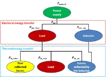
The model of an induction heating device takes three energy fluxes into consideration: the electrical power transfer of the heating device, the metal heating and the coil cooling. A schematic diagram of the fluxes is drawn in Fig. 1. The useful flux is the energy flux 𝑃𝑡ℎ_𝑙𝑜𝑎𝑑 required by the load to be heated to reach its final temperature. The other fluxes
Fig. 1: Diagram of energy fluxes of an induction heating device
The inverter yield defined as the ratio between the MF power 𝑃𝑡𝑜𝑡 and the network power 𝑃𝑛𝑒𝑡𝑤𝑜𝑟𝑘 is assumed to be
constant.
The electric yield is defined as:
𝜂𝑒 =
𝑃𝑒𝑙𝑒𝑐 𝑙𝑜𝑎𝑑
𝑃𝑡𝑜𝑡 = 1 −
𝑃𝑒𝑙𝑒𝑐 𝑖𝑛𝑑
𝑃𝑡𝑜𝑡 (1)
The Joule losses into the coil 𝑃𝑒𝑙𝑒𝑐 𝑖𝑛𝑑 depend on the temperature 𝜃 of the coil considered equal to the fluid cooling it.
Assuming that the copper tube of the coil is thicker than the skin depth, the losses are proportional to the square root of the copper resistivity 𝜌𝐶𝑢 𝜃 . Knowing the electric yield at a reference temperature 𝜃𝑟𝑒𝑓, it is possible to evaluate the
electric yield at any coil temperature.
𝜂𝑒 𝜃 = 1 − 1 − 𝜂𝑒 𝜃𝑟𝑒𝑓 ∙
𝜌𝐶𝑢 𝜃
𝜌𝐶𝑢 𝜃𝑟𝑒𝑓
(2)
The thermal yield is defined as:
𝜂𝑡ℎ = 𝑃𝑡ℎ 𝑙𝑜𝑎𝑑 𝑃𝑒𝑙𝑒𝑐 𝑙𝑜𝑎𝑑 = 1 − 𝑃𝑡ℎ 𝑖𝑛𝑑 + 𝑃𝑡ℎ 𝑜𝑡ℎ𝑒𝑟 𝑃𝑒𝑙𝑒𝑐 𝑙𝑜𝑎𝑑 = 1 − 𝑃𝑡ℎ 𝑖𝑛𝑑 𝛾 ∙ 𝑃𝑒𝑙𝑒𝑐 𝑙𝑜𝑎𝑑
with 𝛾 =
𝑃𝑡ℎ 𝑖𝑛𝑑 𝑃𝑡ℎ 𝑖𝑛𝑑+𝑃𝑡ℎ 𝑜𝑡 ℎ𝑒𝑟 (3)Considering that the cooling fluid temperature does not impact the load temperature 𝜃𝑙𝑜𝑎𝑑 and that the thermal flux
𝑃𝑡ℎ 𝑖𝑛𝑑 is mainly conductive, its evolution with the cooling fluid temperature is evaluated as:
𝑃𝑡ℎ 𝑖𝑛𝑑 𝜃 = 𝑃𝑡ℎ 𝑖𝑛𝑑 𝜃𝑟𝑒𝑓 ∙
𝜃𝑙𝑜𝑎𝑑 − 𝜃
𝜃𝑙𝑜𝑎𝑑 − 𝜃𝑟𝑒𝑓 (4)
Assuming the ratio 𝛾 as constant, it is possible to evaluate the thermal yield at any coil temperature. 𝜂𝑡ℎ 𝜃 = 1 − 1 − 𝜂𝑡ℎ 𝜃𝑟𝑒𝑓 ∙
𝜃𝑙𝑜𝑎𝑑 − 𝜃
Other modeled equipments
A library of models written in Modelica language was developed in the frame of the project CERES [3]. Some of these components are used to build the ISIS software: boilers, heat exchanger, space heating, hot water production, bath heating, Organic Rankine Cycle (ORC), thermoelectricity, heat recovery on hot pieces. For each component, only few parameters are requested to describe it completely.
Case study Costs hypothesis
The selection of the recovery solution takes into account not only the technical feasibility but also the economical relevance. Each component is characterized by its investment and operating costs. As the objective of the study is to recover as much energy as possible on already existing heating device, only the investment costs of the added equipments are considered. Table 1 summarizes the assumptions taken in the model (source EDF).
Table 1: Investment and operating costs
Equipment Investment costs Annual operating costs
Boiler Null: already exists Gas consumption: 30 €/MWh
Inductor Null: already exists Electricity consumption: 70 €/MWh Cooling water Null: already exists Electricity consumption of the pump Heat exchanger for coil recovery Device + installation: 220 €/m2 4% of investment costs
Heat exchanger with hot pieces 2 options tested:
- using superheated steam - using organic fluid
Data not available
Organic Rankine Cycle Function of installed electric power Electricity production: 70 €/MWh Thermoelectricity 3 000 €/MWe installed Electricity production: 70 €/MWh
Case study of a forge workshop
This first case study is representative of a forge workshop producing 4.3 t/h of steel forged pieces using an 1.4 MW induction heating device. At 35 °C reference coil temperature, the inverter, electric and thermal yields are equal to respectively 93.4 %, 83.2 % and 90.0 %. 𝛾 coefficient is taken as 90 %. Coil losses and hot pieces cooling are the two heat sources available for recovery. Two situations were considered: reuse in the forging process alone and reuse elsewhere in the process or for building heating.
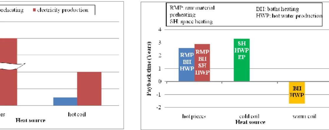
Fig. 2: Payback time: forging process alone Fig. 3: Payback time: forging process + process baths + building heating
In the first situation (forging process alone), the only available reuses are the preheating of raw material before induction heating and the electricity production. Payback times are shown Fig. 2 for different scenarios. It appears that the conversion into electricity is never profitable. Preheating using respectively hot pieces (1,250 °C) cooling and hot coil (300 °C) cooling generates 161 k€/year and 61 k€ saving leading to a payback time of, respectively 2.8 and 2.4 years. Recovering energy from cold coil is never profitable.
In the second situation, the collected energy can also be reused in relay of a boiler inside the process line for heating pickling baths (need: 800 kW) or washing baths (40 kW) or for space heating (146 kW) or domestic hot water
production (1.8 kW). Payback times are shown Fig. 3 for different scenarios. The hot pieces cooling recovery scenarios are the most profitable ones; they generate respectively 111 k€/year and 168 k€/year with or without space heating reuse. The cold coil recovery root uses thermoelectricity to produce electricity partially transformed to space heating generating 6 k€/year savings with a payback time of 3.3 years. Warm coil (70 °C) recovery is immediately profitable (negative payback) and generates 7 k€/year savings.
Case study of a foundry
The second case study is representative of a foundry producing 4.3t/h of cast iron, 8 hours a day, 5 days per week. The melting device is a 5 MW coreless induction crucible. In this workshop, the collected energy can be reused in relay of a boiler for space heating (146 kW) or domestic hot water production (1.8 kW) or converted into electricity via an Organic Rankine Cycle or a thermoelectric system, as proposed in [4]. None of the studied scenarios is profitable: operating costs including amortization of the added equipments are always higher than the costs of the reference situation and the benefits of the energy saving is too small. Recovering energy does not make sense in this configuration; it may be relevant only if the workshop requires other needs than domestic hot water or space heating.
Conclusion
Software ISIS based on the Pinch method is able to propose solutions to recover fatal losses of an induction heating device coming either from inductor Joule losses or from heated pieces after treatment. A specific model describes the induction heating device, taking into account the temperature of the fluid cooling the coil. The model of the other equipments comes from CERES library.
This modeling tool was applied to a steel forging workshop and a cast iron foundry. The most relevant solutions propose to recycle the heat coming from the cooling of the hot pieces after treatment and use it elsewhere in the process line (raw material preheating or pickling bath heating). Recycling Joule losses with hot fluid cooling is less relevant although the payback time remains below 3 years. Conversion into electricity is rarely relevant.
Acknowledgment
This work has been supported by French Research National Agency (ANR) through Éfficacité énergétique et réduction des Émissions de CO2 dans les Systèmes Industriels program (project ISIS ANR-09-EESI-004)
References
[1] B. Linnhoff, E. Hindmarsch, “The pinch design method for heat exchanger networks”, s.l.: Chemical Engineering Science, 1983
[2] Natural Resources Canada, “Pinch analysis: for the efficient use of energy, water & hydrogen”, ISBN: 0-662-34964-4, 2003
[3] A. Zoughaib, M. Feidt, S. Pelloux-Prayer, F. Thibault, Van Long Le, “Chemins énergétiques pour la récupération d’énergies (CERES)”, Congrès Français de Thermique, 3-6 June 2014