HAL Id: hal-01620030
https://hal.archives-ouvertes.fr/hal-01620030
Submitted on 15 Mar 2019
HAL is a multi-disciplinary open access
archive for the deposit and dissemination of
sci-entific research documents, whether they are
pub-lished or not. The documents may come from
teaching and research institutions in France or
abroad, or from public or private research centers.
L’archive ouverte pluridisciplinaire HAL, est
destinée au dépôt et à la diffusion de documents
scientifiques de niveau recherche, publiés ou non,
émanant des établissements d’enseignement et de
recherche français ou étrangers, des laboratoires
publics ou privés.
Machinability analysis of dry drilling of carbon/epoxy
composites: cases of exit delamination and cylindricity
error
M. F. Ameur, M. Habak, M. Kenane, H. Aouici, Mohammed Cheikh
To cite this version:
M. F. Ameur, M. Habak, M. Kenane, H. Aouici, Mohammed Cheikh. Machinability analysis of
dry drilling of carbon/epoxy composites: cases of exit delamination and cylindricity error.
Interna-tional Journal of Advanced Manufacturing Technology, Springer Verlag, 2017, 88 (9), pp.2557-2571.
�10.1007/s00170-016-8967-8�. �hal-01620030�
Machinability analysis of dry drilling of carbon/epoxy
composites: cases of exit delamination and cylindricity error
M. F. Ameur1,2&M. Habak3&M. Kenane1&H. Aouici4&M. Cheikh5
Abstract The aim of this work is to define the cutting condi-tions that allow the dry drilling of carbon fiber reinforced epoxy (CFRE) composite materials taking into consideration the quality of the drilled holes (the exit delamination factor and the cylindricity error) and the optimum combination of drilling parameters. A further aim is to use grey relational analysis to improve the quality of the drilled holes. The ma-chining parameters were measured according to 33full
facto-rial parameter designs (27 experiments with independent pro-cess variables). The experiments were carried out under vari-ous cutting parameters with different spindle speeds and feed rates. Drilling tests were done using WC carbide, high-speed steel (HSS), and TiN-coated carbide drills. The experiment design was accomplished by application of the statistical anal-ysis of variance (ANOVA). Results show that the thrust force is mainly influenced by the tool materials and the feed rate, which has a strong influence on the exit delamination factor. On the other hand, the spindle speed particularly affects the
cylindricity error of the holes. Correlations were established between spindle speed/feed rate and the various machining parameters so as to optimize cutting conditions. These corre-lations were found by quadratic regression using response surface methodology (RSM). Finally, tests were carried out to check the concordance of experimental results.
Keywords CFRE composites . Response surface methodology . Dry drilling . Cutting parameters . Exit delamination factor . Cylindricity error
1 Introduction
In industrial fields such as aerospace and aircraft manufactur-ing, carbon fiber reinforced epoxy (CFRE) composites are used, because of their excellent mechanical properties. Drilling of composite materials is a very common process in the assembly of aeronautic composite structures. However, the machinability of these composites makes it difficult to yield good-quality products.
With regard to the quality characteristics of drilled holes in CFRE, some problems have been encountered, including sur-face delamination and fiber pullout. With the increasing de-mand for advanced composite materials, different cutting con-ditions are required. Delamination is the most common defect when drilling. This is because of the heterogeneity between fibers and matrix [1]. Some studies have concluded that the delamination factor is related to the thrust force when drilling composite materials [2].
Davim et al. [3] presented a correlation between cutting velocity and feed rate with the delamination of carbon fiber reinforced laminate composites. Recently, Tsao[[4] examined the drilling-induced thrust force of a composite polymer (CFRP) material, with a step-core drill, by taking into
* M. F. Ameur
1 Laboratoire des Sciences et Génie des Matériaux, Faculté de Génie Mécanique et Génie des Procédés USTHB, BP 32, El-Alia, Bab Ezzouar, Algeria
2 Ecole Nationale Supérieure de Technologie, Cité Diplomatique Dergana-Bordj El Kiffan, Alger, Algeria
3 Laboratoire des Technologies Innovantes (LTI), IUT d’Amiens, Dépt GMP, Université de Picardie Jules Verne, Avenue Facultés Bailly, 80001 Amiens, France
4 Laboratoire Mécanique et Structures (LMS), Département de Génie Mécanique, FST, Université 08 Mai 1945, Guelma 24000, Algeria 5 Université de Toulouse, IUT de Figeac, Mines Albi, ICA (Institut
consideration the diameter ratio, feed rate, and spindle speed parameters. For the same material, Zitoune et al. [5] improved drilling by using various dimensions of a double cone drill with analysis including cutting force, tool lifetime, chip form, and hole quality. Elsewhere, Li et al. [6] detailed the effect of variable feed rate and lay-up configuration on surface rough-ness and integrity following the drilling of CFRP composites under chilled air conditions. Gaitonde et al. [7] analyzed the effects of process parameters on delamination under high-speed drilling using CFRP. Rawat et al. conducted similar experiments [8], but with carbon fiber and a different epoxy matrix. With the same carbon/epoxy composite plates, Piquet et al. [9] investigated the effect of drilling with two types of drills, a conventional twist drill and specific cutting tool. Luís Miguel et al. [10] performed drilling tests with different drills, and the resulting delamination extensions were measured by digital-enhanced radiography and evaluated using the compu-tational techniques of image processing and analysis. Capello [11] studied the differences in delamination mechanisms in drilling with and without a support placed below the glass fiber reinforced plastic work piece. Bhatnagar et al. [12] stud-ied the orthogonal cutting of unidirectional carbon fiber rein-forced epoxy composite with different fiber orientations. Rajamurugan et al. [13] analyzed delamination in drilling glass fiber reinforced polyester composites. An attempt has been made to develop empirical relationships between the drilling parameters. Khashaba et al. [14] treated the effect of drill pre-wear on the machinability parameters when drilling glass fiber reinforced epoxy composites (GFRE) under differ-ent cutting conditions. Linear regression models were devel-oped to correlate the machinability parameters with the drill wear and cutting conditions.
Rubio et al. [15] chose the Taguchi method to identify the best drilling setup of a glass reinforced polyamide. Another approach, based on a combination of Taguchi’s techniques and the analysis of variance (ANOVA), was used to investi-gate the cutting characteristics of CFRP with high-speed steel (HSS) and cemented carbide drills [3]. In other studies, Sardinas et al. [16] used a micro-genetic algorithm and Krishnamoorthy et al. [17] a fuzzy grey method both with the aim of optimizing the drilling process conditions. Gaitonde et al. analyzed the effects of cutting speed, feed rate, and angle point on the delamination factor by generating re-sponse surface methodology (RSM) plots models [7].
Although numerous research studies have been carried out on the effects of cutting parameters on delamination during the drilling of CFRP composites, few have been reported on the effect of the geometric quality of the hole [18].
The studies mentioned above discuss the cutting of com-posite materials, but they make no assumptions about geomet-ric cylindgeomet-ricity defects.
The present work investigates the dry drilling of carbon/ epoxy composite (CFRE) plates. The twisted tools used are
from HSS, carbide, and TiN-coated carbide, all with the same dimensions (6-mm diameter, 118° point angle, and 30° helical angle).
The effect of the cutting parameters (spindle speed and feed rate) on generated cutting forces and hole quality were stud-ied. ANOVA was used to examine the significance and the relevance of the models used to draw the response surface in order to estimate the influence and the simultaneous interac-tion of the cutting parameters (rotainterac-tion speed (N) and feed rate ( f )) on the studied phenomena (thrust force (Fz), torque (Mz), exit delamination factor, and the cylindricity error).
2 Experimental procedure
2.1 Tests and materials
Dry drilling experiments were carried out on a CNC vertical milling machine. Three different tool materials were used for the drill: HSS,-coated carbide, and carbide, with different spindle speeds and feed rates. Experimental results were col-lected and recorded by a data acquisition system. The exper-imental conditions are summarized in Table1.
The material used in the present investigation consisted of CFRE plates (with dimensions of 200 × 200 × 8 mm3) manufactured through hand layup of [90°/+45°/0°/−45°]3s
un-der a vacuum pressure of 97 MPa. The obtained thickness of the cured plate was of 8 mm.
To check the homogeneity of the prepared composite plates and calculate the fiber volume fraction, three samples of (10 × 10 × 8) mm3were cut off from different plates. The fiber content was determined by pyrolysis at a temperature of 450 °C. The obtained volume fiber fraction was equal to 67.16 % with a standard deviation estimated at 1.22 %. The mechanical properties of the material are described in Table2. The workpiece was mounted on a Kistler platform (9257B type) in order to measure the thrust force and the torque ap-plied on the workpiece during the drilling process.
Geometric inside-hole defects were analyzed on a three-dimensional measuring machine (CMM) with a spherical probe of 3 mm in diameter. The measurement of the inlet and the outlet hole diameters and the cylindricity error were obtained by palpation at 24 points on the circumference of the
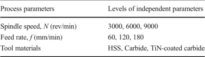
Table 1 Cutting conditions
Process parameters Levels of independent parameters Spindle speed, N (rev/min) 3000, 6000, 9000
Feed rate, f (mm/min) 60, 120, 180
hole at 2 mm from the upper (entry hole) and lower (exit hole) free surface, as shown in Fig.1.
Delamination is a damage phenomenon, which occurs due to the anisotropy and brittleness of composite ma-terials. The damage (delamination) surrounding the holes was measured using a tool maker’s microscope. The exit delamination factor was calculated using the following equation:
Fd ¼Dmaxd ð1Þ
where the parameters Fd, Dmax, and d are the
delamina-tion factor, the maximum diameter measured in the damaged zone, and the diameter of the drill, respectively.
The exit delamination factor was calculated at the exit side of the drill. Performance characteristics, name-ly thrust force, torque, exit delamination, and cylindricity error, are presented in Table 3, along with
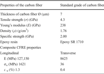
Table 2 Properties of materials (fiber and resin)
Properties of the carbon fiber Standard grade of carbon fiber Thickness of carbon fiber Ø (μm) 7
Tensile strength (σ) (GPa) 4.3 Young’s modulus (E) (GPa) 238 Density (ρ) (g/cm3) 1.76 Specific strength (GPa) 2.00
Epoxy resin Epoxy SR 1710 Composite CFRE properties
Longitudinal Transverse E (MPa) 127,150 8625 σu(MPa) 1621 36 εu(%) 1.3 0.4 KISTLER DYNAMOMETER (9257B) DRILLING CUTTING PARAMETERS Spindle speed (N) Feed rate (f)
Drills:HSS,WC and WC-TiN
Thrust force and torque measurement Cylindricity error measurement SEM
Delamination factorFd measurement
MICROSCOPE UMM 3-MESUREMENT FROM WENZEL GERMANY
Fig. 1 Schematic of experimental processes
the input drilling parameters (spindle speed, feed rate, and tool materials).
2.2 Response surface methodology
Response surface methodology is a collection of math-ematical and statistical techniques that are useful for the modeling and analysis of problems in which a response of interest is influenced by several variables and the purpose is to optimize this response [14, 18]. In our study, the response surface methodology (RSM) com-prised the following six major components:
(1) Defining the independent input variables and the desired output responses.
(2) Drawing up an experimental design plan.
(3) Using response surface regression equations to find the relationship between the factors Fz, Mz, Fd-Exit, and
cylindricity error by quadratic regression.
(4) Using ANOVA statistical analysis to find parameters which significantly affect the output.
(5) Obtaining the optimal set of experimental param-eters that produces a maximum or minimum out-put value.
(6) Verifying and confirming the predicted performance characteristics by experiment.
3 Results and discussion
The machining parameters were measured according to 33full factorial designs (27 experiments with actual independent pro-cess variables). The measured responses (output) are shown in Table 2. They were analyzed by Design-Expert software which indicated that quadratic models were statistically recommended.
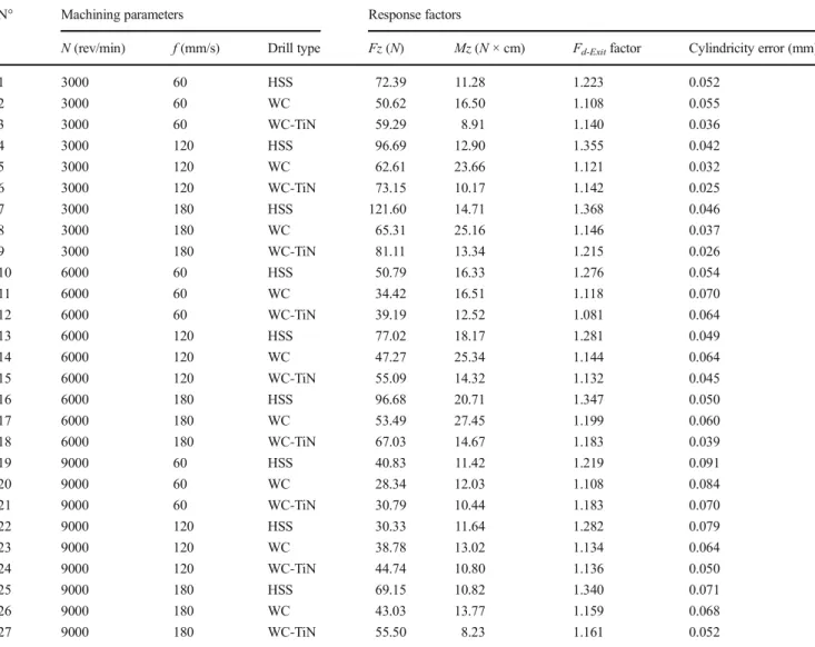
Table 3 Experimental results for Fz, Mz, Fd-Exit, and cylindricity error
N° Machining parameters Response factors
N (rev/min) f (mm/s) Drill type Fz (N) Mz (N × cm) Fd-Exitfactor Cylindricity error (mm)
1 3000 60 HSS 72.39 11.28 1.223 0.052 2 3000 60 WC 50.62 16.50 1.108 0.055 3 3000 60 WC-TiN 59.29 8.91 1.140 0.036 4 3000 120 HSS 96.69 12.90 1.355 0.042 5 3000 120 WC 62.61 23.66 1.121 0.032 6 3000 120 WC-TiN 73.15 10.17 1.142 0.025 7 3000 180 HSS 121.60 14.71 1.368 0.046 8 3000 180 WC 65.31 25.16 1.146 0.037 9 3000 180 WC-TiN 81.11 13.34 1.215 0.026 10 6000 60 HSS 50.79 16.33 1.276 0.054 11 6000 60 WC 34.42 16.51 1.118 0.070 12 6000 60 WC-TiN 39.19 12.52 1.081 0.064 13 6000 120 HSS 77.02 18.17 1.281 0.049 14 6000 120 WC 47.27 25.34 1.144 0.064 15 6000 120 WC-TiN 55.09 14.32 1.132 0.045 16 6000 180 HSS 96.68 20.71 1.347 0.050 17 6000 180 WC 53.49 27.45 1.199 0.060 18 6000 180 WC-TiN 67.03 14.67 1.183 0.039 19 9000 60 HSS 40.83 11.42 1.219 0.091 20 9000 60 WC 28.34 12.03 1.108 0.084 21 9000 60 WC-TiN 30.79 10.44 1.183 0.070 22 9000 120 HSS 30.33 11.64 1.282 0.079 23 9000 120 WC 38.78 13.02 1.134 0.064 24 9000 120 WC-TiN 44.74 10.80 1.136 0.050 25 9000 180 HSS 69.15 10.82 1.340 0.071 26 9000 180 WC 43.03 13.77 1.159 0.068 27 9000 180 WC-TiN 55.50 8.23 1.161 0.052
3.1 Regression equations
RSM leads to an appropriate approximation for the true functional relationship between design parameters Y and a set of independent variables. Usually, a second-order model is used in response surface methodology [19, 20]: Y ¼ b0þ Xk i¼1 bixiþ Xk i¼1 biix2i þ Xk i〈 j bi jxixjþ ε ð2Þ
where xi is the value of the ith machining process
parameter. The terms b0, b1…bk, and b11,..,bkk
repre-sent the regression coefficients. The residual ε indicates the experimental error. The second-order response sur-face Y is a function of the cutting parameters (the spin-dle speed N and feed rate f). The relationship between the response and the machining parameters is given by: Y ¼ b0þ b1N þ b2f þ b3N2þ b4f2þ b5N % f ð3Þ
where b0, …, b5 are the regression coefficients
associ-ated with the model.
The relationship between the design and the cutting parameters were modeled by quadratic regression. For the thrust force Fz, the models are given in Eqs. 4–6
for three different tool materials, namely carbide, high-speed steel, and TiN-coated carbide drills. Their coeffi-cients of determination (R2) are 95.26, 99.40, and
99.64 %, respectively. FzðHSSÞ¼ 75:01889−0:035139 % f −8:74444 % 10−4 % N−2:90139 % 10−5% f % N þ 2:00741 % 10−3% f2−3:33148 % 10−7% N2 ð4Þ FzðWCÞ¼ 51:64333 þ 0:38025 % f −7:87278 % 10−3 % N−2:46716 % 10−20% f % N−1:02361 % 10−18 % f2þ 3:39444 % 10−7% N2 ð5Þ FzðWC⋅TiNÞ¼ 66:76667 þ 0:3275 % f −9:94611 % 10−3 % N þ 4:01389 % 10−6% f % N−6:04167 % 10−4 % f2þ 4:06667 % 10−7% N2 ð6Þ
The torque (Mz) models are given in Eqs.7 to9. Their coefficients of determination R2 are 96.77, 94.91, and
94.42 %. MzðHSSÞ¼ −11:54333 þ 0:055278 % f þ 8:76 % 10−3 % N−5:59722 % 10−6% f % N−6:94444 % 10−6 % f2−6:97222 % 10−7% N2 ð7Þ MzðWCÞ¼ −12:08444 þ 0:25717 % f þ 7:33889 % 10−3 % N−9:61111 % 10−6% f % N−5:84259 % 10−4 % f2−6:38148 % 10−7% N2 ð8Þ MzðWC⋅TiNÞ¼ −8:73556 þ 0:094917 % f þ 5:63833 % 10−3% N−9:22222 % 10−6% f % N−1:14352 % 10−4% f2−3:91296 % 10−7% N2 ð9Þ The delamination-exit (Fd-Exit) factor models are shown in
Eqs.10to12with coefficients of determination R2of 83.95, 92.32, and 79.28 %, respectively. Fd−Exit HSSð Þ¼ 1:151 þ 1:83611 % 10−3% f þ 2:833 % 10−6% N−3:3333 % 10−8% f % N−2:91667 % 10−6% f2−3:88889 % 10−10% N2 ð10Þ Fd−Exit WCð Þ¼ 1:02622−8:05556 % 10−5% f þ 3:17222 % 10−5% N þ 1:80556 % 10−8% f % N þ 1:85185 % 10−6% f2−2:7037 % 10−9% N2 ð11Þ Fd−Exit WC−TiNð Þ¼ 1:1918−3:5 % 10−4% f −2:58889 % 10−5 % N−1:34722 % 10−7% f % N þ 6:62037 % 10−6 % f2þ 3:42593 % 10−9% N2 ð12Þ The cylindricity error models are illustrated in Eqs.13to15 with coefficients of determination R2 of 98.41, 96.12, and
97.4 %, respectively.
Cylindricty % errorðHSSÞ¼ 0:07667−2:3333 % 10−4
% f −8:7222 % 10−6% N−1:9444 % 10−8% f % N þ 1:1111 % 10−6% f2þ 1:3889 % 10−10% N2 ð13Þ
Cylindricy % errorðWCÞ¼ 0:04867−7:3889 % 10−4% f
þ 1:5444 % 10−5N þ 2:7778 % 10−9% f % N þ 2:5 % 10−6% f2−8:88889 % 10−10% N2 ð14Þ
Cylindricty % errorðWC⋅TiNÞ¼ 0:03211−6:0278 % 10−4% f
þ 1:4278 % 10−5N−1:1111 % 10−8% f % N þ 2:17593 % 10−6% f2−6:85185 % 10−10% N2
ð15Þ 3.2 Statistical analysis
The analysis of variance (ANOVA) method consists of fractioning the total variation in an experiment into compo-nents ascribable to controlled factors and errors.
Table4summarizes the variant analysis results of the thrust force (Fz), torque (Mz), delamination exit factor (Fd-Exit), and cylindricity error, respectively, of composite (CFRE) drilling. This analysis was carried out for a significance level of 5 %, i.e., for a confidence level of 95 %. These tables indicate the degree of freedom DF, sum of squares SC sq., mean square MS, F values, probabilities (P value), and the percentage of contribution (Cont. %) of each factor to the total variation. At the bottom of each table, the values of the determination co-efficients R2, the adjusted R2((Adj-R2), the predicted R2 ((Pred-R2), and the adequate precision are given.
The analysis of the first part of Table4shows that the feed rate, tool, the interactions N × tool, tool × tool, and especially the spindle speed (with a contribution of 41.68 %) have a great influence on the thrust force. The interactions (N × f), (f × tool), (N × N), and (f × f) do not present any significant con-tribution on the obtained thrust force. Their concon-tributions are 0.22, 1.66, 0.08, and 0.01 %, respectively.
Furthermore, R2is 91.27 %, Adj-R2is 86.64 %, and
Pred-R2is 78.11 %. Therefore, in this case, the value of the Pred-R2
is in reasonable agreement with the Adj-R2value. Thus, the
thrust force model can be used to navigate the response space. Adequate precision compares the range of predicted values at the design points to the average prediction error. It is a mea-sure of the signal to noise ratio. A ratio greater than 4 indicates adequate model precision, and in this particular case, it was found to be 19.18, which is well above the adequate precision limit.
In the second part of Table4, the torque (Mz) is presented. These results show that the interaction tool × tool (Cont. = 41.25 %) and interaction spindle speed N × N (Cont. = 26.88 %) have the most significant influence on the torque (Mz). However, the spindle speed (Cont. = 11.02), the feed rate (Cont. = 10.05 %), and the tool (Cont. = 5.61 %) are
less significant. These results also show that N × f, N × tool, f × f, and f × tool interactions are negligible. The model works well in torque analysis with R2equal to 83.48 % which
indi-cates a more preponderant fit of the model. The Pred-R2of
59.66 % is in reasonable agreement with the Adj-R2of 74.73 %. The signal to noise ratio obtained here is 10.37, which is well above 4 and shows an adequate signal.
It is clear from the ANOVA results that the tool is the dominant factor affecting the exit delamination factor (F d-Exit) (third part of Table 4) with a contribution of 57.06 %.
The second factor influencing Fd-Exitis the tool × tool
interac-tion (Cont. = 27.65). The interacinterac-tion feed rate has a contribu-tion of 14.12 %. It is the most significant parameter related to the exit delamination factor. The spindle speed N and interac-tions N × f, N × tool, N × N, f × f, tool × tool, and the tool factor do not present any significant contribution to the obtained F d-Exit. The model for surface roughness gives values of R2,
Adj-R2, and Pred-R2of 92.33, 88.26, and 78.16 %, respectively. It
is worth mentioning that the Pred-R2is in reasonable
agree-ment with the Adj-R2. These values should be used as indica-tions of correctness of fit.
Finally, the results in the fourth part of Table4(cylindricity error) indicate that the model is still significant. Spindle speed (Cont. = 63.38 %), feed rate (Cont. = 13.23 %), cutting tool (Cont. = 13.23 %), second-order effect of tool (tool × tool) (Cont. = 4.41 %), and feed rate (f × f) (Cont. = 4.27 %) are the significant terms of the model. The spindle speed is the most significant factor related to cylindricity error. This is expected because it is well known that with the increase in the spindle speed, tool vibration increases. This induces an increase in the cylindricity error [11]. The ANOVA table in-dicates that the interactions (N × f), (N × tool), (f × tool), and (N × N) do not present any significant contribution to the cutting temperature obtained (calculated value of F is more than the table value; F0.05, 1, 17= 4.45) at 95 % confidence
level. The value of R2 is 90.10 % of the total variability,
Adj-R2is 84.87 %, and the Pred-R2is 76.26 %. The latter is
in reasonable agreement with the value of Adj-R2. Adequate
precision of 14.83 is an adequate value for the model to per-form well in prediction.
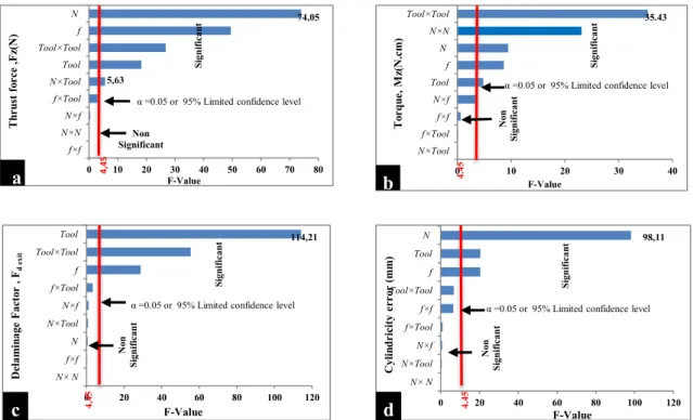
3.3 Pareto graph
To give better view of the results of the analysis of variance, Pareto graphs were built (see Fig. 2). This figure ranks the cutting parameters and their interactions according to their growing influence on the thrust force (Fz), torque (Mz), exit delamination factor (Fd-Exit), and cylindricity error.
Standardized values for this figure were obtained by dividing the effect of each factor by the error on the estimated value of the corresponding factor. If the F values were greater than 4.45, the effects were considered to be significant. Conversely, if the F value was less than 4.45, the effects were
not considered significant. The confidence interval chosen was 95 %. F table corresponding to a 95 % confidence level in the accurate calculation of the process parameters was F0.05, 1, 17= 4.45.
To verify the adequacy of the model obtained by ANOVA analysis, the normality assumption of the residual must be verified. Figure 3a, bshows normal probability plots of the residuals. These figures reveal that all the residuals follow a
straight line pattern which is in good agreement with the re-sults reported by Shahrajabian et al. [21].
4 Response surface analysis
A 3D response surface model was generated to exhibits the interaction effects due to spindle speed N and feed
Table 4 ANOVA result-model variation
Source Sum of squares DF Mean square F value Prob. Cont. % R2% Adj-R2% Pred-R2% AP
Thrust force (Fz) Model 12097.63 9 1344.18 19.74 <0.0001 91.27 86.64 78.11 19.18 N 5042.76 1 5042.76 74.05 <0.0001 41.68 F 3368.56 1 3368.56 49.47 <0.0001 27.84 Tool 1243.18 1 1243.18 18.26 0.0005 10.28 N × f 27.00 1 27.00 0.40 0.5373 0.22 N × tool 383.64 1 383.64 5.63 0.0297 3.17 f × tool 200.49 1 200.49 2.94 0.1044 1.66 N × N 9.21 1 9.21 0.14 0.7176 0.08 f × f 1.25 1 1.25 0.018 0.8940 0.01 Tool × tool 1821.55 1 1821.55 26.75 <0.0001 15.06 Error 1157.67 17 68.10 Total 13255.30 26 100 Torque (Mz) Model 598.89 9 66.54 9.54 <0.0001 83.48 74.73 59.66 10.37 N 65.97 1 65.97 9.46 0.0068 11.02 F 60.21 1 60.21 8.64 0.0092 10.05 Tool 33.57 1 33.57 4.81 0.0424 5.61 N × f 25.78 1 25.78 3.70 0.0714 4.30 N × tool 0.35 1 0.35 0.051 0.8245 0.06 f × tool 0.67 1 0.67 0.096 0.7600 0.11 N × N 160.99 1 160.99 23.09 0.0002 26.88 f × f 4.30 1 4.30 0.62 0.4430 0.72 Tool × tool 247.04 1 247.04 35.43 <0.0001 41.25 Error 118.52 17 6.97 Total 717.42 26 100 Fd exit Model 0.17 9 0.019 22.73 <0.0001 92.33 88.26 78.16 15.58 N 5.120E-004 1 5.120E-004 0.61 0.4470 0,30 F 0.024 1 0.024 28.81 <0.0001 14,12 Tool 0.097 1 0.097 114.21 <0.0001 57,06 N × f 9.720E-004 1 9.720E-004 1.15 0.2985 0,57
N × tool 6.453E-004 1 6.453E-004 0.76 0.3944 0,38
f × tool 2.760E-003 1 2.760E-003 3.27 0.0884 1,62
N × N 6.000E-006 1 6.000E-006 7.100E003 0.9338 0,00
f × f 2.667E-004 1 2.667E-004 0.32 0.5816 0,16
Tool × tool 0.047 1 0.047 55.40 <0.0001 27,65
Error 0.014 17 8.450E-004
Total 0.19 26 100
Cylindricity error
Model 6.774E-003 9 7.527E-004 17.20 <0.0001 90.10 84.87 76.26 14.83
N 4.294E-003 1 4.294E-003 98.11 <0.0001 63.38
F 8.961E-004 1 8.961E-004 20.47 0.0003 13.23
Tool 8.961E-004 1 8.961E-004 20.47 0.0003 13.23
N × f 3.333E-005 1 3.333E-005 0.76 0.3950 0.49
N × tool 2.133E-005 1 2.133E-005 0.49 0.4945 0.31
f × tool 4.408E-005 1 4.408E-005 1.01 0.3296 0.65
N × N 1.852E-006 1 1.852E-006 0.042 0.8395 0.03
f × f 2.894E-004 1 2.894E-004 6.61 0.0198 4.27
Tool × tool 2.987E-004 1 2.987E-004 6.82 0.0182 4.41
Error 7.440E-004 17 4.376E-005
0 10 20 30 40 50 60 70 80 f×f N×N N×f f×Tool N×Tool Tool Tool×Tool f N 4, 45 74,05 5,63 F-Value Th ru st fo rce ,F z( N)
α =0.05 or 95% Limited confidence level
Signif icant Non Significant
a
0 10 20 30 40 N×Tool f×Tool f×f N×f Tool f N N×N Tool×Tool To rq ue ,M z( N.cm )α =0.05 or 95% Limited confidence level
Non Signif icant F-Value 4. 45 Signif icant 35.43
b
0 20 40 60 80 100 120 N× N f×f N N×Tool N×f f×Tool f Tool×Tool Tool Delam in age Fa cto r , Fd ex it F-Value Signif icant Non Signif icantα =0.05 or 95% Limited confidence level
4, 45 114,21
c
0 20 40 60 80 100 120 N× N N×Tool N×f f×Tool f×f Tool×Tool f Tool N F-Value Non Signif icantα =0.05 or 95% Limited confidence level
Cylin dricity erro r (m m ) Signif icant 98,11 4. 45
d
Fig. 2 Pareto graph:,a Thrust force, b torque, c exit delamination factor, and d cylindricity error
(a) Thrust force (b) Torque
(c)Exitdelamination factor (d) Cylindricity error
rate f on thrust force Fz, torque Mz, delamination factor at the exit (Fd-Exit), and the cylindricity error during
drilling of CFRE composites. These were analyzed for three different drill materials: high-speed steel, carbide, and coated carbide through response surface plots (Figs. 4, 5, 6, and 7).
4.1 Effect of drilling parameters on thrust forces
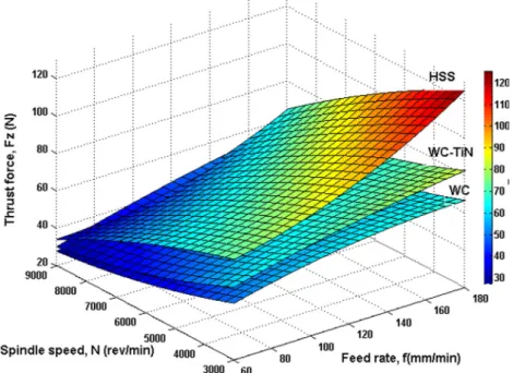
The thrust force generated during drilling of CFRE composites depends on input variables, such as cutting speed or spindle speed, feed rate, and drill materials. This effect is summarized in Fig. 4. The thrust force greatly increases with the feed rate. However, the thrust force changes only slightly when the spindle speed varies. It can also be observed in this figure that drilling with the HSS drill leads to a higher thrust force com-pared to WC and WC-TiN drills. Furthermore, it can be noticed that for a spindle speed of 3000 rev/min with a feed rate varying from 60 to 180 mm/min, the drilling thrust force of CFRE composites using WC,WC-TiN, and HSS tools is subjected to an increase of 22.64, 26.64, and 40.47 %, respectively.
From these figures, it was noted that for the smallest feed rate (60 mm/min) and a spindle speed varying from 3000 (rev/min) to 9000 (rev/min), the thrust force for the three drills (HSS, WC, and WC-TiN) was slightly reduced. It is known that increasing the spindle speed raises the temperature of machining, which is due to the friction between the tool and the CFRE composite materials, which in turn results in a soften-ing of the material and a subsequent reduction in thrust force [20].
4.2 Effect of drilling parameters on torque
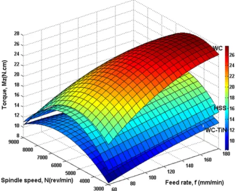
Drilling torque obtained from the regression model and the optimum torque for the three drills (HSS, WC, and WC-TiN) is exhibited by the three-dimensional response surface model shown in Fig. 5. It can be observed that the torque increases noticeably with the feed rate for the three drilling tools. Drill materials have a significant effect on the torque during the drilling of the CFRE composites. In addition, max-imal torque values are obtained when drilling composite lam-inates with a speed spindle of 6000 rev/min, for all three tool materials. For the same spindle speed of 6000 rev/min, the WC drill was subjected to the highest torque value when the feed rate was 180 mm/min.
Furthermore, Fig.5 indicates that at a high spindle speed (9000 rev/min) and a low feed rate (60 mm/min), the three drills were subjected to a low torque value in the drilling of CFRE composites.
4.3 Effect of drilling parameters on the exit delamination factor
From the response surface analysis in Fig. 6, it can be seen that the exit delamination factor is highly sensitive to the feed rate variation. It can also be observed from Fig. 6 that delamination has a tendency to increase with the feed rate during drilling of CFRE composites for the different drills (HSS, WC, and WC-TiN). In addition, the HSS drill has the greatest effect on delamination compared with the other tools.
Figure6clearly shows that the combination of low values of feed rate and spindle speed is useful in the WC tool during drilling of CFRE composites in order to reduce damage at the
Fig. 4 Effect of spindle speed and feed rate on thrust force for HSS, carbide, and TiN-coated carbide
exit of the holes, and that delamination decreases with a high cutting speed (9000 rev/min).
Again according to Fig. 6, it is observed that the rise in spindle speed slightly diminishes the exit delamina-tion factor. The reason for this is that the temperature produced in the drilling of composites increases with the spindle speed, which softens the matrix material and increases shearing, which diminishes delamination. The high feed rate increases both the thrust force in drilling and the exit delamination factor [11].
This result can be explained by the fact that at high cutting speed, the cutting edge action is reduced, and that the friction between cutting edges and board causes temperature elevation and softening, thus reducing damage.
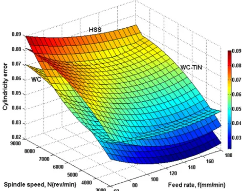
4.4 Effect of machining parameters on cylindricity error The influence of the feed rate and spindle speed on the cylindricity error using the HSS, WC, and WC-TiN drills is illustrated in Fig.7. It can be observed that the cylindricity
Fig. 5 Effect of spindle speed and feed rate on torque for HSS, carbide, and TiN-coated carbide
Fig. 6 Effect of spindle speed and feed rate on exite delamination factor (Fd-exit) for HSS, carbide, and TiN-coated carbide
error is related linearly to both spindle speed and feed rate. The high spindle speed increases the cylindricity error in the drilling of composite materials for the different drills (HSS, WC, and WC-TiN). It is the most influential parameter on the quality of the holes, in particular the cylindricity error. On the other hand, the effect of the feed rate on the cylindricity error is insignificant for the lowest spindle speed, 3000 rev/min, and only slight for the highest spindle speed of 9000 rev/min.
It was concluded that the combination between the maxi-mum spindle speed and the minimaxi-mum feed rate for the three tools gives a maximum cylindricity error. Hence, the smallest cylindricity error is obtained from the combination of the low-est spindle speed and the highlow-est feed rate.
5 Surface quality of machined holes
SEM observation revealed several damaged areas when the holes were machined with a WC twist drill, as shown in Fig.8. These damaged areas were mainly observed at fiber orienta-tions of−45° and 90°. However, in WC-Ti machining, there were fewer damage areas and lower depths of damage com-pared to WC drilling. Also, it was found that damage was uniformly distributed. Figure8displays the SEM observation of the last nine cut composite layers (90°,45°,0°,−45°, 90°, 45°, 0°, and −45°) for the holes drilled into the CFRE composite.
The SEM photograph illustrates several cases of fiber pull-out and a series of interlaminar delamination damage. The extent of this damage depends mainly on the fiber orientation and the cutting parameters [22].
Observations, as illustrated in Fig.8, show that the surface hole accumulated melted matrix material between the plies. This is possibly caused by the increased tool-workpiece con-tact time coupled with a low feed rate leading to relatively higher interfacial temperatures. The weak thermal conductiv-ity of CFRE was a further contributory factor in causing the resin to melt.
A close-up view of the distribution of fibers at a 90° angle is illustrated in Fig.8a. The material removal is initiated by an opening, which penetrates the material below the cutting di-rection, according to the fiber/matrix interface, extended by a secondary rupture, which rises to the shear fibers, as shown in Fig.9a[23].
The SEM analysis also illustrates that the cutting of the fibers of plies with −45° orientation causes pullout of the
Fig. 7 Effect of spindle speed and feed rate on cylindricity error for HSS, carbide, and TiN-coated carbide Toolfeed direc!on 90° 0° 45° 90° -45° 45° 0° -45° 90° Fibre pullout Exit Delamina!on Smearing of matrix Delamina!on
fibers, leading to significant damage in the form of cavities (see Fig.8). With the cutting of−45° oriented fibers illustrated in Fig.9b, the fibers bend. Significant defects propagate inside the material and eventually pullout and tear the fibers [24,25]. Chip separation occurs after fiber rupture in a direction perpendicular to their axis. During the cutting of plies at 0° orientation, the tool delaminates the fibers easily creating small defects Fig.8. Machining of fibers at 0° can produce large fragmented debris. The fibers are stressed and this in-duces buckling which causes cracking (Fig.9c).
For plies of 45° orientation, the chip formation mechanisms begin with shearing of the fibers and then of the matrix, along the fiber/matrix interface to the free surface, as illustrated in Fig.9c. During cutting of the fibers oriented at 45°, the cutting tool reached the layer directly, and very small composite de-bris were formed.
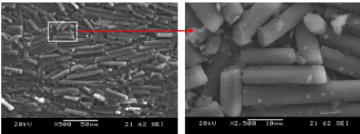
It can be seen that the drilling of composites produces tiny fiber particle chips, as shown in Fig.10, with dimensions not exceeding roughly 20μm.
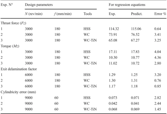
6 Confirmation experiments
The comparison between the expected values of the model developed in the present work (Eqs.1to15) and the values obtained experimentally is shown in Table5. It illustrates the calculated errors as follows: thrust force (Fz) (max. value 3.41 % and min. value 0.64 %), torque (Mz) (max. value 4.36 % and min. value 2.80 %), exit delamination factor (F
d-Exit) (max. value 3.20 % and min. value 0.76 %), and
cylindricity error (mm) (max. value 2.82 % and min. value 1.45 %). All the confirmation experiment values are within the 95 % prediction interval. Therefore, Eqs. (1) to (15) correlated the evolution of thrust force, torque, exit delamination factor, and cylindricity error with the cutting conditions (spindle speed and feed rate) with a reasonable degree of approximation.
7 Optimization of cutting conditions
In this study, a desirability function approach was used for multiple response parameters, namely thrust force (Fz), torque (Mz), exit delamination factor (Fd-Exit), and cylindricity error. Design-Expert software was used for this optimization exer-cise. During the optimization process, the aim was to find the optimal values of machining parameters in order to produce the lowest thrust force, torque, surface roughness, and cutting
a) 90°orientated plies b)-45°orientated plies
c) 0°orientated plies d)45° orientated plies
Fig. 9 SEM photographs of fracture of the hole drilled at different orientations of fiber. a 90° orientated plies, b−45° orientated plies, c 0° orientated plies, and d 45° orientated plies
temperature. To solve this type of parameter design problem, an objective function, F(x), is defined as follows [21]:
DF ¼ ∏ n i¼1d w i ! 1 Xn j−1wi F xð Þ ¼ −DF ð16Þ
with dithe desirability defined for the ith required output
and withe weighting of di.
For different objectives of required output, the desirability diis defined in variable forms. If an objective is to attain a
particular value of Ti, the desirability dibecomes:
di ¼ 0 if Yi≤Lowi or Yi≥Highi di¼ Yi−Lowi i Ti−Lowi ! " if Lowi≤Yi≤Ti di¼ Yi−Highi i Ti−Highi ! " if Ti≤Yi≤Highi ð17Þ
where Yi is the value found of the ith output during the optimization process and Lowi and Highiare the minimum
and maximum values for the same output. If the objective is to find the maximum value, the desirability will be:
di ¼ 0 if Yi≤Lowi or Yi≥Highi
di¼ Yi−Lowi i
Highi−Lowi
! "
if Lowi≤Yi≤Highi ð18Þ
If the objective is to find a minimum value, the desirability is defined as follows: di¼ 0 if Yi≤Lowi or Yi≥Highi di¼ Highi−Yi i Highi−Lowi ! "
if Lowi≤Yi≤Highi ð19Þ
In Eq. (16), wiis put as equal to one, since the diall have the
same weight in this work. DF is a combined desirability
Table 5 Confirmation of
experiment results Exp. N° Design parameters For regression equations
N (rev/min) f (mm/min) Tools Exp. Predict. Error % Thrust force (Fz) 1 3000 180 HSS 114.32 115.06 0.64 2 3000 180 WC 73.91 76.52 3.41 3 3000 180 WC-TiN 65.08 67.27 3.25 Torque (Mz) 1 3000 180 HSS 17.11 17.83 4.04 2 3000 180 WC 10.30 10.77 4.36 3 3000 180 WC-TiN 11.02 10.72 2.80 Exit delamination factor
1 6000 180 HSS 1.29 1.25 3.20 2 6000 180 WC 1.30 1.31 0.76 3 6000 180 WC-TiN 1.17 1.18 0.85 Cylindricity error (mm) 1 9000 60 HSS 0.073 0.071 2.82 2 9000 60 WC 0.042 0.041 2.44 3 9000 60 WC-TiN 0.068 0.069 1.45
Table 6 Constraints for
optimization of cutting conditions Condition Goal Lower limit Upper limit Importance Spindle speed, N (rev/min) Is in range 3000 9000
Feed rate, f (mm/min) Is in range 60 180 Tool materials Is in range (1) HSS, (2) WC, (3) WC-TiN
Thrust force (Fz) Minimize 28.34 121.6 **** Torque (Mz) Minimize 8.23 27.45 **** Exit delamination (Fd-Exit) Minimize 1.081 1.368 ***** Cylindricity error Minimize 0.025 0.091 *****
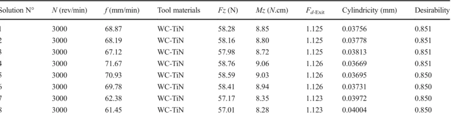
function. The purpose here is to find the best solution that max-imizes a combined desirability function DF, i.e., minmax-imizes F(x). The optimal manufacturing conditions for the drilling of composite CFRE with the constraints of the cutting parametric range are those corresponding to the lowest values of thrust force (Fz), torque (Mz), exit delamination factor (Fd-Exit), and
cylindricity error during the dry drilling process. The con-straints used during the optimization process are summarized in Table6, whereas the optimal solutions are reported in Table7. This same table shows the RSM optimization results for thrust force, torque, exit delamination factor, and cylindricity error. The optimum cutting parameters in Table7were obtained with a spindle speed of 3000 rev/min, a feed rate of (61.45 to 71.67) mm/min, and the WC-TiN tool material. The optimized thrust force, torque, Fd-Exit, and
cylindricity error are (57.01 to 58.76) N, (8.28 to 9.06) N × cm, (1.040 to 1.041), (1.123 to 1.126), and (0.03669 to 0.04004) mm, respectively.
8 Conclusions
This research work presents the application of RSM models to the study of the influence of machining parameters on thrust force, torque, exit delamination factor, and cylindricity error.
The relationship between the factors and the measured per-formance were modeled by quadratic regression. Three pro-cess variables, namely spindle speed, feed rate, and tool ma-terials, were used for the development of the models. The RSM models were developed then tested using ANOVA. The actual models were found to satisfy the optimization of the machining parameters at a 95 % confidence interval. Through this analysis, conclusions about machining force, exit delamination factor, and cylindricity error were deduced: & Drilling forces were significantly influenced by tool ma-terials. Since the degree of drilling force induced in the drilling process is associated with the power requirements, which is in turn correlated to production costs, a low thrust force and torque were preferred. In this study, coated
carbide (WC-Ti) drills induced the lowest drilling forces while HSS drills produced the highest drilling forces. Therefore, coated carbide drills present more advantages for CFRE composites drilling.
& The 3D response surface plots clearly indicate the exis-tence of non-linear relationships between the process pa-rameters and the machinability characteristics and thus justifying the use of a quadratic model.
& The error associated with the ANOVA table (maximum val-ue 4.36 % and minimum valval-ue 0.64 %) for the factors and the coefficients was obtained by the quadratic regression (maximum value 92.33 % and minimum value 83.48 %). & Comparison of experimental and predicted values of
thrust force, torque, exit delamination factor, and cylindricity error shows that the good agreement has been achieved between them. Therefore, the developed model can be recommended for use in predicting thrust force, torque, exit delamination factor, and cylindricity error. & Verification of the experiments carried out shows that the
empirical models developed can be used for CRFE com-posites drilling.
& Hence, it is clear that a reduction in the cylindricity error for drilling composites can be achieved by using a low spindle speed and high feed rate.
& The recommended levels of the drilling parameters allowing minimal thrust force, torque, exit delamination factor, and cylindricity error simultaneously are the feed rate at level 1 (∼60 mm/min), the drill type at level 3 (WC-Ti), and the spindle speed at level 1 (3000 rev/min). Fz, thrust force (N); HSS, high-speed steel; Mz, torque (N × cm); N, spindle speed (rev/min); f, feed rate (mm/s); Fd-Exit,
factor of delamination-exit.
Acknowledgments This work was completed in the Laboratory of Materials Science and Engineering (University USTHB, Algeria) in col-laboration with the Laboratory of Innovative Technologies (LTI), University of Picardie Jules Verne, France). The authors would like to thank the Algerian Ministry of Higher Education and Scientific Research (MESRS) and the Delegated Ministry for Scientific Research (MDRS) for granting financial support for CNEPRU.
Table 7 Optimization results
Solution N° N (rev/min) f (mm/min) Tool materials Fz (N) Mz (N.cm) Fd-Exit Cylindricity (mm) Desirability 1 3000 68.87 WC-TiN 58.28 8.85 1.125 0.03756 0.851 2 3000 68.19 WC-TiN 58.16 8.80 1.125 0.03778 0.851 3 3000 67.12 WC-TiN 57.98 8.72 1.125 0.03813 0.851 4 3000 71.67 WC-TiN 58.76 9.06 1.126 0.03669 0.851 5 3000 70.93 WC-TiN 58.59 9.03 1.126 0.03695 0.850 6 3000 69.78 WC-TiN 58.41 8.94 1.126 0.03731 0.850 7 3000 62.38 WC-TiN 57.17 8.35 1.123 0.03972 0.850 8 3000 61.45 WC-TiN 57.01 8.28 1.123 0.04004 0.850
References
1. Chen WC (1997) Some experimental investigations in the drilling of carbon fibre reinforced composite laminations. Int J Mach Tools Manuf 37(8):1097–1108
2. Paulo Davim J, Reis P (2003) Drilling carbon fiber reinforced plas-tics manufactured by autoclave experimental and statistical study. Mater Des 24:315–324
3. Davim JP, Reis P (2003) Study of delamination in drilling carbon fiber reinforced plastic (CFRP) using design experiments. Compos Struct 59:481–487
4. Tsao CC (2008) Experimental study of drilling composite materials with step-core drill. Mater Des 29:1740–1744
5. Zitoune R, El M, Krishnaraj V (2013) Tribo-functional design of double cone drill implications in tool wear during drilling of copper mesh/CFRP/woven ply. Wear 302:1560–1567
6. Lia MJ, Sooa SL, Aspinwalla DK, Pearsonb D, Leahyc W (2014) Influence of lay-up configuration and feed rate on surface integrity when drilling carbon fibre reinforced plastic (CFRP) composites. Procedia CIRP 13:399–404
7. Gaitonde VN, Karnik SR, Rubio Campos J, Correia Esteves A, Abrao AM, Paulo Davim J (2008) Analysis of parametric influence on delamination in high-speed drilling of carbon fiber reinforced plastic composites. J Mater Process Technol 203:431–438 8. Rawat S, Attia H (2009) Characterization of the dry high speed
drilling process of woven composites using machinability maps approach. CIRP Annals ManufTechnol 58:105–108
9. Piquet R, Ferret B, Lachaud F, Swider P (2000) Experimental anal-ysis of drilling damage in thin carbon/epoxy plate using special drills. Compos Part A 31:1107–1115
10. Durão LMP, Tavares JMRS, de Albuquerque VHC, Gonçalves DJS (2013) Damage evaluation of drilled carbon/epoxy laminates based on area assessment methods. Compos Struct 96:576–583 11. Capello E (2004) Workpiece damping and its effect on delamination
damage in drilling thin composite laminates. J Mater Process Technol 148:186–195
12. Bhatnagar N, Ramakrishnan N, Naik NK, Komanduri R (1995) On the machining of fiber reinforced plastic (FRP) composite lami-nates. Int J Mach Tools Manuf 35:701–716
13. Rajamurugan TV, Shanmugam K, Palanikumar K (2013) Analysis of delamination in drilling glass fiber reinforced polyester compos-ites. Mater Des 45:80–87
14. Khashaba UA, EI-Sobaty IA, Selmy AI, Megahed AA (2010) Machinability analysis in drilling woven GFR/epoxy composites: part I—effect of machining parameters. Compos Part A 41: 391–400
15. Rubio Juan Carlos C, Rubio JCC, da Silva LJ, de Oliveira Leite Tulio Hallak Panzera W, Sergio Luiz Moni Ribeiro F, João Paulo D (2013) Investigations on the drilling process of unreinforced and reinforced polyamides using Taguchi method Composites. Part B Eng 55:338–344
16. Sardinas RQ, Reis P, Davim JP (2006) Multi-objective optimization of cutting parameters for drilling laminate composite materials by using genetic algorithms. Compos Sci Technol 66:3083–3088 17. Krishnamoorthy A, Rajendra Boopathy S, Palanikumar K, Paulo
Davim J (2012) Application of grey fuzzy logic for the optimization of drilling parameters for CFRP composites with multiple perfor-mance characteristics. Measurement 45:1286–1296
18. DeFuLiu YJT, Cong WL (2012) A review of mechanical drilling for composite laminates. Compos Struct 94:1265–1279
19. Aouici H, Bouchelaghem H, Yallese MA, Elbah M, Fnides B (2014) Machinability investigation in hard turning of AISI D3 cold work steel with ceramic tool using response surface methodology. Int J Adv Manuf Technol 73:1775–1788
20. Haijin W, Jie S, Jianfeng L, Laixiao L, Nan L (2016) Evaluation of cutting force and cutting temperature in milling carbon fiber-reinforced polymer composites. Int J Adv Manuf Technol 82(9): 1517–1525
21. Shahrajabian H, Farahnakian M (2013) Modeling and multi-constrained optimization in drilling process of carbon fiber rein-forced epoxy composite. Int J Precis Eng Manuf 14:1829–1837 22. Rubio JCC, Abrao AM, Faria PE (2008) Delamination in high
speed drilling of carbon fiber reinforced plastic (CFRP). J Compos Mater 42(15):1523–1532
23. Sahraie Jahromi A, Bahr B, Krishnan KK (2014) An analytical method for predicting damage zone in orthogonal machining of unidirectional composites. J Compos Mater 48(27):3355–3365 24. Zhenchao Q, Kaifu Z, Hui C, Dong W, Qingxun M (2015)
Microscopic mechanism based force prediction in orthogonal cutting of unidirectional CFRP. Int J Adv Manuf Technol 79:1209–1219
25. Cadorin N, Zitoune R, Seitier P, Collombet F (2015) Analysis of damage mechanism and tool wear while drilling of 3D woven com-posite materials using internal and external cutting fluid. J Compos Mater 49(22):2687–2703