UNIVERSITÉ DE MONTRÉAL
SEISMIC BEHAVIOUR, NUMERICAL MODELLING AND DISPLACEMENT-BASED DESIGN OF STEEL STORAGE RACK STRUCTURES FOR CANADIAN APPLICATIONS
EMILY JACOBSEN
DÉPARTEMENT DES GÉNIES CIVIL, GÉOLOGIQUES ET DES MINES ÉCOLE POLYTECHNIQUE DE MONTRÉAL
MÉMOIRE PRÉSENTÉ EN VUE DE L’OBTENTION DU DIPLÔME DE MAÎTRISE ÈS SCIENCES APPLIQUÉES
(GÉNIE CIVIL) JANVIER 2017
UNIVERSITÉ DE MONTRÉAL
ÉCOLE POLYTECHNIQUE DE MONTRÉAL
Ce mémoire intitulé :
SEISMIC BEHAVIOUR, NUMERICAL MODELLING AND DISPLACEMENT-BASED DESIGN OF STEEL STORAGE RACK STRUCTURES FOR CANADIAN APPLICATIONS
présenté par : JACOBSEN Emily
en vue de l’obtention du diplôme de : Maîtrise ès sciences appliquées a été dûment accepté par le jury d’examen constitué de :
M. LÉGER Pierre, Ph. D., président
M. TREMBLAY Robert, Ph. D., membre et directeur de recherche M. HIGGINS Peter, M.Sc., membre
DEDICATION
ACKNOWLEDGEMENTS
Professor Robert Tremblay for patience, criticism, encouragement and generosity with time and guidance. Thank you for suggesting this gem of a project.
Poulad Daneshvar for advice, the selection and scaling of accelerograms and investigations of pallet sliding and cooperation on analysis of time history results in CHAPTER 4 .
Peter Higgins B.Sc., M,Sc, M.E.Sc. P.Eng and Prof. Pierre Leger for having accepted to sit as members of the jury.
Ihor Koval on whose undergraduate project this masters project expanded and who aided during the physical tests.
Martin Leclerc and Romain Sigieur for the design of the physical testing apparatuses and procedures, direction of test setup and operation of instrumentation and laboratory equipment. Émile Lord and Aziz El Meskini for their participation in test set-up and the other members of the GRS laboratory staff.
The members of the S16 Rack Annex sub-committee for their advice and review of designs, as well as materials for physical tests and testing data for connections.
Financial support for this project was generously provided by NSERC Discovery and Engage grant programs.
RÉSUMÉ
Les étagères industrielles en acier, fabriquées des profilés formés à froid ou laminés à chaud sont mise en œuvre dans une panoplie de contextes tels que des centres de distribution ou des centres commerciaux où l’on charge avec des pallets de marchandises souvent accessibles au grand public. Ces étagères sont habituellement composées des cadres contreventés dans l’une des directions et des cadres semi-rigides dans la direction orthogonale. Les cadres sont semi-rigides en raison des connecteurs poutres-colonnes qui se doivent d’être faciles à reconfigurer afin de s’adapter aux besoins du propriétaire. Ce projet vise la caractérisation de la réponse séismique de ces cadres semi-rigides et le développement d’un modèle robuste de ces derniers ainsi que la validation des provisions, actuellement en état de développement, à l’Annexe du Code canadien sur le calcul des charpentes d’acier.
Onze essais physiques sur des spécimens d’un étage formés à froid ont été effectués à Polytechnique Montréal. Cette configuration simple a pour but l’isolation de la réponse des connecteurs poutres-colonnes, des plaques de base et du glissement des pallets, réduisant le problème à l’essentiel afin de produire un modèle précis de son comportement. Parmi les essais étaient trois du type quasi statique, deux essais vibrations libres et six essais sur la table vibrante. Les essais quasi statiques comportaient trois configurations d’étagère : rotulé à la base avec des connecteurs aux accroches, rotulés au niveau des poutres avec des plaques de base conventionnelles, et connecteurs aux accroches avec des plaques de base. Les deux essais vibrations libres comportaient un spécimen avec plaques de base et l’autre avec rotules, les deux avec connecteurs aux accroches. Les six essais restants étaient divisés de façon égale entre des spécimens rotulés à leur base et des spécimens avec des plaques de base. Ces spécimens subissaient des tremblements de terre de l’est et de l’ouest du Canada.
La réponse séismique des étagères était gouvernée par la plastification des connecteurs poutres-colonnes, par la plastification des plaques de base et par la dissipation d’énergie due au glissement des pallets. Les poutres et les colonnes demeuraient élastiques à l’exception de la surface des colonnes où se faisait l’interface avec les connecteurs. Le modèle aux éléments finis, fruit des essais quasi statiques et de vibrations libres était modifié suite aux essais séismiques pour prendre en compte l’action des palets. Le modèle final emploi une gamme de matériels dans les ressorts concentrés, avec des lois de comportement multilinéaires, intégrant de la dégradation,
afin de reproduire l’action des connecteurs, plaques de base et palets. En combinaison avec des colonnes et des poutres élastiques, le modèle parvient à reproduire les déplacements et les accélérations des essais physiques.
Les essais quasi statiques menés à Polytechnique se concordent avec des tests indépendants sur les connecteurs. En conjonction avec le constat que la réponse globale est dictée par la plastification de ces connecteurs (et plaques de base), le modèle peut être généralisé à d’autres combinaisons de poutres, de colonnes, de connecteurs et de plaques de base en se servant d’autres données disponibles pour les connecteurs. Le modèle est généralisé encore plus en incluant des colonnes de fibre, des poutres à plasticité concentrée et des plaques de base sensibles au niveau de compression appliquée. Ces derniers permettent l’analyse d’autres configurations d’étagère. Ces dernières modifications assurent que l’hypothèse de poutres et colonnes linéaires n’est pas dépassée de façon inaperçue.
Pour aider avec la validation des provisions séismiques, quatre étagères (de 3 à 6 étages et 6-baies) conçues selon la pratique actuelle ont été analysées suivant l’Annexe N. Ensuite, ces étagères ont été reconçus pour les conditions de site de Vancouver et Montréal sites C & E avec le plus petit de marge de sécurité possible par rapport aux provisions de l’Annexe. Les méthodes par déplacements et par force ont été suivies. Les provisions pour la conception par force ont conduit à des membrures et connecteurs irréalistes. Les étagères conçues selon la méthode par déplacements ont été raisonnables. Par la suite, ces étagères prototypes ont été assujetties à une suite de séismes représentatifs de l’est et de l’ouest du Canada. Ces analyses constituent le repère pour des analyses multiparamétriques à venir. Les étagères ont réagit tel que prévue sauf quelques exceptions importantes – les étagères très flexibles sont susceptibles l’effondrement malgré le fait qu’elles rencontrent les critères de déformation et de résistance latérale stipulés dans l’Annexe N.
ABSTRACT
Rack shelving structures, made of cold-formed or hot-rolled members, are used in a variety of contexts, in storage and distribution centres and in publicly accessible warehouse type stores stacked with merchandise on pallets. Racks are typically composed of braced-frames in the “cross-aisle” direction and semi-rigid moment-frames in the “down-aisle” direction. The moment-frames are semi-rigid due to their clip-in or bolt-on beam-column connections which allow easy assembly and geometric modifications according to user needs. This project aims to characterise the seismic response of these semi-rigid moment frames, develop a robust model and test the proposed seismic design provisions currently under development as an annex to the CSA S16 – Design of steel structures.
Eleven physical tests were carried out on 1-bay, 1-level cold-form specimens at Polytechnique Montréal. This simple configuration was chosen to isolate the response of beam-column connections, base-plates and pallet sliding and facilitate accurate modelling of their behaviour. The tests included quasi-static tests, free-vibration tests and six-seismic tests. Quasi-static tests were performed on three different configurations: pinned-base with clip-in beam-column connections, fix-base with pinned beam-column connections and fix-base with clip-in connections. Two free vibration tests were conducted on pin-based and fix-based specimens both with clip-in beam column connections. The remaining six uni-directional seismic tests were equally divided between pin-base and fix-base specimens subjected to eastern and western Canadian quakes.
Seismic response of the racks was governed by yielding of the beam-column connections, yielding of the base-plates and energy dissipation due to sliding of the pallets. Beams and columns remained elastic except where the connectors clip-in to the columns. The finite element model developed during the quasi-static and free-vibration test stages was modified following the seismic tests to include the action of pallet sliding. This model uses an assortment of materials with multi-linear rules and various types degradation in zero-length springs to reproduce accurately the non-linear action of the beam-column connectors, base-plates and pallets. Combined with elastic beams and columns, the model succeeds in reproducing displacements and accelerations observed in the seismic tests.
The quasi-static tests performed at Polytechnique Montreal compared favorably to independent testing of the beam-column connections. Combined with the fact that overall response is dictated by the yielding of these connectors (and base-plates), this allowed generalization of the finite element model to other configurations of beams, columns, connectors and base-plates using test data available for the connections. The model was expanded to include in-plane buckling of the column elements, yielding of beams at their junction with the non-linear connector elements and base-plate assemblies able to accommodate changes in strength and stiffness with increased compression. This ensures that many combinations of beams, columns, connectors and base-plates may be analyzed in multi-bay, multi-level configurations while validating the hypothesis that beams and column remain elastic.
To aide the validation of the seismic provisions of the proposed annex, four racks (3 to 6 levels and 6-bays) designed according to current industry practice were analyzed according to guidelines set out in the Annex. These racks were then redesigned to give as close as possible match to the guidelines and to accommodate seismic conditions in Vancouver and Montreal sites C & E. Design procedures following a displacement-based method and a force-based method of analysis were followed. The guidelines for the force-based method resulted in unrealistic designs and are currently under revision. Racks designed according to the displacement-based method were subjected to non-linear time history analysis with a representative number of quakes for eastern and western Canada. These analyses constitute the base-line series, in a planned series of multi-parameter analyses. These racks performed as expected with some exceptions, notably very flexible racks were susceptible to collapse despite having met both the deformation and minimum lateral resistance stipulations of Annex N.
TABLE OF CONTENTS
DEDICATION ... III
ACKNOWLEDGEMENTS ... IV
RÉSUMÉ ... V
ABSTRACT ... VII TABLE OF CONTENTS ...IX LIST OF TABLES ... XIII LIST FO FIGURES ...XV LIST OF SYMBOLS AND ABBREVIATIONS ...XXIII LIST OF APPENDICES ... XXIX
CHAPTER 1 INTRODUCTION ... 1
Problem Under Study ... 1
1.1 Goals of Study ... 3 1.2 Methodology ... 4 1.3 Organisation ... 5 1.4 CHAPTER 2 LITERATURE REVIEW ... 6
Seismic response of rack moment frames ... 6
2.1 Existing standards on rack seismic design ... 7
2.2 2.2.1 Canada ... 7
2.2.2 USA ... 8
2.2.3 Europe ... 10
2.2.4 New Zealand ... 12
Existing applications of DBD to racks ... 12
2.3 Design quandaries ... 14
2.4 2.4.1 Lateral stiffness ... 14
2.4.2 Base plate stiffness and energy dissipation capacity ... 14
2.4.3 Pallet sliding, sloshing & shedding ... 15
2.4.4 Scaling of spectra for damping ... 17
2.4.5 P-delta ... 17
2.4.6 Higher mode participation ... 18
CHAPTER 3 ARTICLE 1: SHAKE-TABLE TESTING AND NUMERICAL MODELING OF INELASTIC SEISMIC RESPONSE OF SEMI-RIGID COLD-FORMED RACK MOMENT FRAMES ...19 Introduction ... 19 3.1 Testing Program ... 23 3.2 3.2.1 Test Setup ... 23
3.2.2 Test matrix and loading protocols ... 26
3.2.3 Results from Quasi-Static Cyclic Tests ... 30
Numerical Modelling ... 36
3.3 3.3.1 Base-plates ... 37
3.3.2 Beam-column connectors ... 38
3.3.3 Base-plate and connector in combination ... 41
Results from Pull-back Tests ... 42
3.4 Results from Seismic Tests ... 46
3.5 3.5.1 Pinned-base specimens ... 46
3.5.2 Fixed-based specimens ... 48
3.5.3 Sliding of pallets ... 50
3.5.4 Numerical modelling of pallet sliding ... 51
3.5.5 Effect of damping modelling on response prediction ... 52
3.5.7 Evaluating equivalent damping by two methods ... 55
Numerical Seismic Response of Multi-level, Multi-bay Racks ... 57
3.6 3.6.1 Structures studied ... 57
3.6.2 Seismic effects on column axial loads ... 59
3.6.3 Displacement profiles ... 59
3.6.4 Pallet sliding ... 60
3.6.5 Drift-rotation relationship ... 61
3.6.6 Influence of added viscous damping ... 62
3.6.7 Influence of base plate flexural strength ... 63
Conclusions and Recommendations ... 64
3.7 Acknowledgements ... 66
3.8 CHAPTER 4 DISPLACEMENT-BASED DESIGN OF RACKS ACCORDING TO ANNEX N AND COMPARISON WITH NON-LINEAR TIME HISTORY ANALYSIS ... 73
Introduction ... 73
4.1 A proposed displacement-based design method for racks ... 73
4.2 Design according to proposed Annex N provisions ... 79
4.3 4.3.1 Properties, dimensions and loads ... 79
4.3.2 Design of 3-level, 6-bay rack in Vancouver site C ... 84
4.3.3 Design of 6-level, 6-bay rack in Montreal site E ... 95
Summary of design of prototype racks ... 103
4.4 Summary of force-based designs ... 106
4.5 Discussion of preliminary results of NLTH trials ... 106
4.6 4.6.1 FEM model ... 107
4.6.2 Displacement profiles ... 107
4.6.4 Collapse Case ... 115
CHAPTER 5 GENERAL DISCUSSION ... 128
CHAPTER 6 CONCLUSIONS AND RECOMMENDATIONS ... 130
Conclusions ... 130 6.1 Recommendations ... 132 6.2 6.2.1 Modelling ... 132 6.2.2 Design ... 132 6.2.3 Further reasearch ... 133 BIBLIOGRAPHY ... 134 APPENDICES …………. ... 148
LIST OF TABLES
Table 3-1: Testing Program ... 27
Table 3-2: Sliding accelerations and distances in seismic tests. ... 51
Table 3-3: Summary of peak drifts from physical tests compared with drift from two models. Test to model prediction ratio in brackets. ... 52
Table 3-4: Equivalent damping properties ... 56
Table 3-5: Strength adjustment factors for different base-plate thickness and compression level 58 Table 3-6: Average peak connector rotations and top drifts of multi-level racks without sliding subject to Q1 ground motion at SF = 1.0 ... 62
Table 4-1: Connectors and product loads for prototype racks. ... 79
Table 4-2: Material properties. ... 83
Table 4-3 : Spectral values for Montreal and Vancouver Sites C & E from NBCC 2015. ... 84
Table 4-4: Finding the generalised displacement coordinate. ... 89
Table 4-5: Column Design Moments ... 92
Table 4-6: Column gravity loads ... 93
Table 4-7: Calculation of minimum lateral resistance. ... 94
Table 4-8: Finding the generalised displacement coordinante of a 6-level rack. ... 98
Table 4-9: Column Design Moments. ... 100
Table 4-10: Column gravity loads. ... 100
Table 4-11 : Minimum lateral resistance. ... 102
Table 4-12: Sections and section inertias (Ib & Ic), material yield limits (Fyb & Fyc), connectors, scaling factors (SFc) and base-plate thickness (tp). ... 103
Table 4-13: Deformation limits (θlim & Δlim), design deformations (θd & Δd) and corresponding connector and base-plate and secant stiffness (kc & kbpl) and energy dissipated by cycle (EDCc & EDCbpl)... 104
Table 4-14: Iterations to converge on displacement of 3-level rack in Montreal Site C. ... 105
Table 4-15: Effective period (Teff) and lateral stiffness (keff) of the structure of the substitute SDOF structure, reduced lateral stiffness (keff,red.) and augmented natural period (Teff,aug.) to account for P-delta, effective damping (βeff), spectral reduction coefficient for damping (Rβ), spectral displacement of the substitute SDOF at 5% and at β (Sd5% & Sdβ), design displacement of the SDOF and design displacement of the real structure (δd & δtot). ... 105
Table 4-16: Summary of expected and calculated connector rotations. ... 114
Table C-1: Distribution of equivalent static forces ……….. 166
Table C-2: Inelastic drift ……….…… 166
Table C-3: Notional loads ……….... 167
Table C-4: U2 factors ………. 168
Table C-5: Connector moments under gravity and lateral loads ………... 168
Table C-6: Connector moments under gravity and lateral loads ………... 169
Table C-7: Amplified connector moments: U2*ME+ MD ………... 169
Table C-8: Notional Loads ……… 171
Table C-9: Inelastic drift ………. 171
Table C-10: U2 factor ………. 171
Table C-11: Connector moments under lateral loads (Fx + Nx) ………. 171
Table C-12: Connector moments under gravity and lateral loads ………... 172
Table C-13: P-delta amplified forces induced by lateral loads + gravity loads: U2ME+MD ... 172
Table C-14: P-delta amplified forces induced by lateral loads + gravity loads: U2ME+MD ... 173
Table C-15: Calculation of U2 factors………... 174
Table C-16: Connector moments under lateral loads (Fx + Nx) ………... 175
LIST OF FIGURES
Figure 1-1: Typical storage rack [7]. ... 1
Figure 1-2: A non-exhaustive sample of available beam-column connections: Clockwise from top-left a bolt-on connector attached to a hot-rolled beam [8], a cold-form column with “tear-drop” clip-in connection [9], a similar cold-form column with another model of connector [10], “redi-rack” type columns and connectors with rolled-beams [11], cold-form and rolled-beams connected to rolled-column via a bolt-on connector [12], HSS columns with bolt-on connectors attached to channel beams [13]. ... 2
Figure 2-1: Base-plate testing assembly as recommended by the FEM and discussed in [32]. .... 15
Figure 2-2: Accounting for P-delta according to [43]. ... 17
Figure 3-1: Test setup (all dimensions in mm): a) Elevation view; b) Side view. ... 24
Figure 3-2 : Loading and instrumentation: a) Linear-pot assembly to measure rotations at beam-column joints; b) instrumentation schematic showing measurement locations; c) Cable and position of load cell during static tests. ... 25
Figure 3-3 : Beam-column connection (all dimensions in mm): a) Photo (taken after testing) and figure of the beam-column connection and section of the column and beam; b) Modified “pinned” beam-column connection in Test F1. ... 26
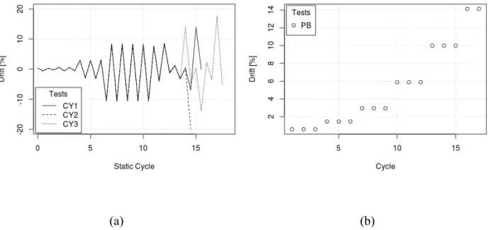
Figure 3-4: Displacement protocols in: a) Quasi-static tests; and b) Pull-back tests. ... 28
Figure 3-5: Test ground motions and corresponding 5% damped displacement spectra. ... 29
Figure 3-6: a) Base-shear vs. average drift measured in test P1; b) Average moment-rotation of a single connector in test P1 compared with RMI cruciform unit test of the same type of connector. ... 31
Figure 3-7: Progression of connector damage in test P1: a) at 0.03 rad little damage; b) at 0.08 rad yielding and buckling begins; c) at 0.1 rad shearing and plate buckling worsens; d) at 0.14 rad connector twists and disengages from column; e) at 0.14 rad weld damage; and f) post-test. ... 32
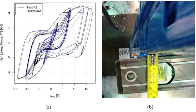
Figure 3-8: Behavior of the specimen F1 as governed by yielding of the base-plate: a) Front view at Δavg = 0.2 ; b) side view at Δavg = 0.2; c) & d) yield-line model parameters on front and
side view; e) top view of yield lines; f) top view base-plate at Δavg = 0.2; g) base-shear vs. average drift measured in test F1. ... 33
Figure 3-9: Base-plate moment-rotation hysteresis: Experimental, analytical and FEM: a) Each material present in FEM model of the base-plate shown individually; b) Comparison between complete FEM model of base-plate and experimental data with select features A & B from yield line model discussion. OpenSees material parameters in SI units; see [41] and [42] for definitions of each parameter. ... 35
Figure 3-10: Test F2: a) Lateral force-displacement relation from test and numerical model (test results are average of two frames including P-delta); b) Level and measuring tape held across the braced frame emphasizes flexural-torsional buckling of the column at 14% drift. ... 36
Figure 3-11: 2D OpenSees FEM model of the rack's moment frame. ... 37
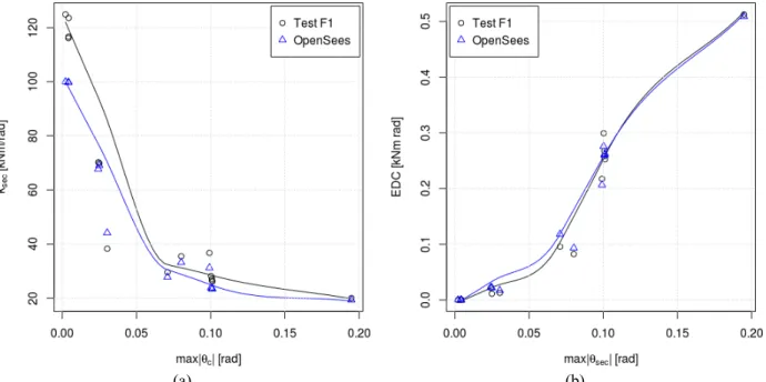
Figure 3-12: Validation of the base-plate model against Test F1 results for: a) Secant stiffness; and b) Energy dissipated per cycle (EDC). ... 38
Figure 3-13: Response of the beam-to-column connector model, with tables showing the parameters for the Pinching4 material in SI units (see [45] for definitions of each parameter) compared to : a) Test P1; b) RMI test. ... 39
Figure 3-14: Validation of the beam-column connector modelling against P1 and RMI test results for: a) Secant stiffness; and b) Energy dissipated per cycle (EDC). ... 40
Figure 3-15: Comparison of test P1 and the numerical model with a small initial stiffness modification: a) Lateral force-load displacement response; and b) Secant stiffness. ... 41
Figure 3-16: Secant stiffness and EDC comparison for test F2. ... 42
Figure 3-17: Comparison between measured and OpenSees free vibration responses for pull-back amplitudes at several drift increments (e.g. “PB @ 10% #2” indicates the second pull (and release) to 10% drift): a) Test P2 with 5% added viscous damping; and b) Test F3 with 2% added viscous damping. ... 43
Figure 3-18: a) Variation of viscous damping calculated at every pair of consecutive peaks over the course of one free vibration test; b) Mean viscous damping calculated from the first four
peaks of amplitude in Tests P2 and F3 compared to OpenSees models with 2 and 5% damping. ... 44
Figure 3-19: Comparison between measured and predicted average natural periods in free vibration Tests P2 and F3. ... 45
Figure 3-20: Drift vs. average rotation during Tests P1 and F2. ... 45
Figure 3-21: Secant stiffness and EDC values from OpenSees model of Test F1 subjected to displacements from RMI cruciform test protocol. ... 46
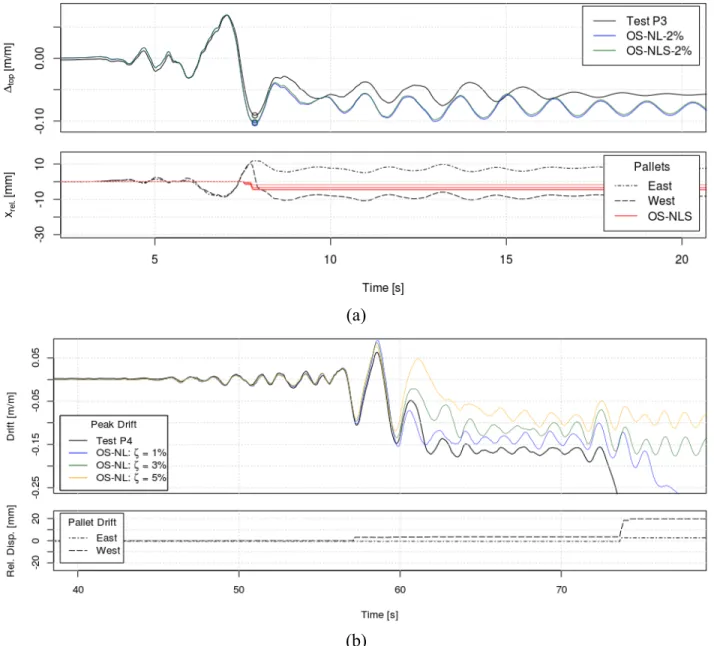
Figure 3-22: Displacement and pallet sliding time history during Tests: a) P3; b) P4; and c) P5. 47
Figure 3-23: Displacement and pallet sliding time histories during Tests: a) F4; and b) F5. ... 49
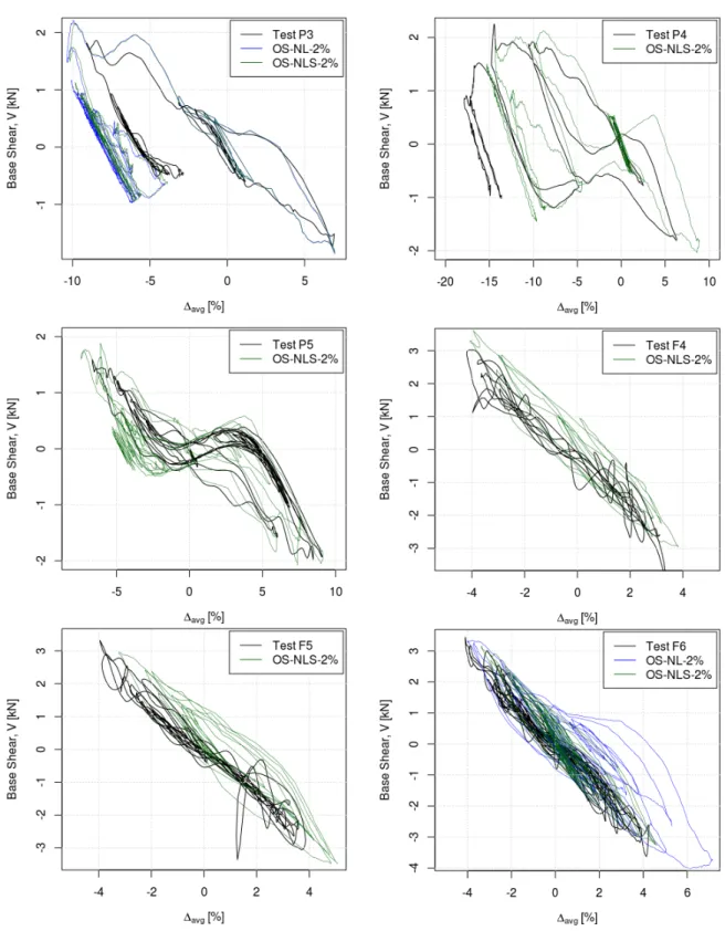
Figure 3-24 : Hysteretic seismic response of specimens versus models with and without sliding. ... 54
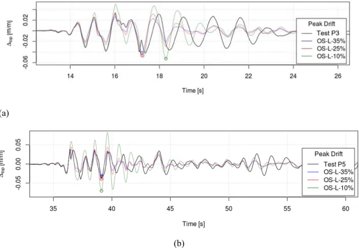
Figure 3-25: Influence of equivalent damping on displacement of the equivalent linear model for Tests: a) P3; and b) P5. ... 57
Figure 3-26: Effect of strength AF on base-plate hysteresis model, compression load for 3-level rack. ... 58
Figure 3-27: Variation of the base vertical reaction on interior and exterior columns. ... 59
Figure 3-28: Drift profiles for multi-level racks subjected to Q1 ground motion at scale factors of 1.0 & 1.5 and ζ = 2%. ... 60
Figure 3-29: Peak rotations and drifts of multi-level racks without sliding subject to Q1 ground motion at SF = 1.0. ... 61
Figure 3-30: Influence of added viscous damping on peak drifts under Q1 ground motion at SF = 1.5. ... 63
Figure 3-31: Drift profiles with stiffened base-plates and increasing scale factors on the Q1 signal. ... 64
Figure 4-1: Calculation of secant stiffness, cycle by cycle, from experimental connector test data. ... 75
Figure 4-2 : Calculation of energy dissipated, cycle-by-cycle, from experimental connector test
data. ... 76
Figure 4-3: Displacement-based design method for racks. ... 78
Figure 4-4: Geometry of prototype racks. ... 79
Figure 4-5: Moment-rotation hysteresis of a single 2-bolt connector AC175. ... 81
Figure 4-6: Moment-rotation hysteresis of a single 3-bolt connector AC200. ... 82
Figure 4-7: Base-plate dimensions for prototype racks. ... 82
Figure 4-8 : Design spectra for Montreal and Vancouver Sites C & E from NBCC 2015. ... 83
Figure 4-9: Drift vs. rotation relationship issue from non-linear pushover of a 3-level rack. ... 86
Figure 4-10: Moment rotation behaviour determined from physical unit tests and strength scaled by a factor of 2.36. ... 87
Figure 4-11: Moment-rotation behaviour as determined from FEM tests. ... 87
Figure 4-12: 1st pass secant stiffness of AC175 connector strength scaled by a factor of 2.36. .. 88
Figure 4-13: 1st pass secant stiffness of 5.5mm base-plates under compressive load of Cf = 44 kN. ... 88
Figure 4-14: 1st pass energy dissipation of AC175 connector calculated from physical tests and strength scaled by a factor of 2.36. ... 88
Figure 4-15: 1st pass energy dissipation of base-plates 5.5mm base-plates under compressive load of Cf = 44 kN. ... 88
Figure 4-16 : Actions on joints of the rack frame a) Top exterior joint b) Top interior joint, c) Middle or bottom exterior joint d) Middle or bottom interior joint. ... 92
Figure 4-17: Drift vs. rotation relationship issue from non-linear pushover of a 6-level rack. .... 96
Figure 4-18: Moment rotation behaviour determined from physical unit tests and strength scaled by a factor of 1.85. ... 96
Figure 4-19: Moment-rotation behaviour as determined from FEM tests under compressive load of Cf = 66.7 kN. ... 96
Figure 4-20: 1st pass secant stiffness of AC175 connector strength scaled by a factor of 1.85. .. 97
Figure 4-21: 1st pass secant stiffness of 2.7mm base-plates under compressive load of Cf = 66.7 kN. ... 97
Figure 4-22: 1st pass energy dissipation of AC175 connector calculated from physical tests and strength scaled by a factor of 1.85. ... 97
Figure 4-23: 1st pass energy dissipation of base-plates 2.7mm base-plates under compressive load of Cf = 66.7 kN. ... 97
Figure 4-24: Displacement profiles from NLTH for racks located in Vancouver site C. ... 108
Figure 4-25: Displacement profiles from NLTH for racks located in Vancouver site E. ... 109
Figure 4-26: Displacement profiles from NLTH for racks located in Montreal site C. ... 110
Figure 4-27: Displacement profiles from NLTH for racks located in Montreal site E. ... 111
Figure 4-28: Comparision of level drifts from non-linear time history analysis and displacement-based design for racks which did not collapse in a) Vancouver site C and b) Vancouver site E. ... 112
Figure 4-29: Comparision of level drifts from non-linear time history analysis and displacement-based design for racks which did not collapse in a) Montreal site C and b) Montreal site E. ... 112
Figure 4-30: Standard deviation in function of peak level drift. ... 114
Figure 4-31: VC30 ground motion. ... 115
Figure 4-32 : Select deformed shapes of the rack during the VC30 ground motion at: a) t = 160.05 s; b) t = 160.7 s; c) t = 166.4 s. ... 116
Figure 4-33 : Displacement time history of each level of a 5-level collapsed rack. ... 117
Figure 4-34 : Deformed shape of rack just before collapse during the VC30 acceleration at t = 179.6 s and 8 % drift. ... 117
Figure 4-35 : Rotation time histories of connectors at joints 1 and 2. ... 118
Figure 4-36 : Moments and equilibrium histories around joint 1 & 2, factored moment resistance of the exterior column, moment needed to cause
yielding (including axial interaction) and the connector moment capacity scaled
for design ∙ , . ... 121
Figure 4-37 : Behavior at below joints 1 & 2: a) & b) Moment-curvature in the exterior column segment below the joints; c) Displacement history of joint 1; d) Time history of interaction equation S16 §13.8.3 (a) (yielding) in the column segments below the joints; e) Column axial load history above and below joint 1; f) Column shear history above and below joint 1; g) & h) connector hysteresis at the joints. ... 122
Figure 4-38 : Close-up deformed shape of exterior column at times of interest with forms of moment diagram. ... 125
Figure 4-39 : Moment distribution in the column at the instant of yielding: a) Form of moment distrubtion near joints 1 & 2 at 175.9 s; b) Free-body diagram of deformed column above and below joint 1. ... 126
Figure B-1 : Over all deformation Test F1 ... 155
Figure B-2 : Typical damage to base plate test F1 ... 155
Figure B-3 : Typical damage to base-plate test F1 ... 155
Figure B-4 : Typical damage to base-plate test F1 ... 156
Figure B-5 : Base-plate uplift ... 158
Figure B-6 : Connectors are not visibly damaged ... 156
Figure B-7 : Shearing of bottom interior tab and bending out top exterior tabs (eastern side) ... 156
Figure B-8 : Shearing of bottom interior tab and bending out of middle and lower exterior tabs (western side) ... 159
Figure B-9 : Plastic hinging of base-plate ... 157
Figure B-10 : Lever effect at base-plate ... 157
Figure B-11 : Vue of the combination of plastic hinging (accompanied by paint flaking) and lever effect ... 158
Figure B-12 : Complete shearing of interior top tabs ... 158
Figure B-14 : Level is held against the braced frame to emphasize the lateral torsional buckling
... 159
Figure B-15 : Lateral torsional buckling of the columns ... 159
Figure B-16 : Local buckling ... 162
Figure B-17 : Progression of base-plate plastic hinging ... 162
Figure B-18 : Beam-connector weld damage as well as progression of tab shearing ... 161
Figure B-19 : Close-up for torn 2nd tab on NE connection ... 162
Figure B-20 : Twisting of connection ... 164
Figure B-21 : Twisting ... 164
Figure B-22 : SW close-up ... 164
Figure B-23 : NE connector close-up showing rupture of 1st tab ... 164
Figure B-25 : Shearing of top tab ...165
Figure B-26 : Complete shear first (top) tab ...165
Figure B-27 : Close-up for torn 2nd tab on NE connection...165
Figure B-28 : Typ. Shearing and/or loss of 1st and 2nd tabs...165
Figure B-29 : Close-up of NE weld rupture ...165
Figure B-30 : Column damage typ.: deformation is most pronounced around bottom connector hole...166
Figure B-31 : Typ. All deformation is taking place in the connection ...166
Figure B-32 : Typ. Local buckling on the face of the connector ...166
Figure B-33 : Typ. Connector after test ...166
Figure B-34 : Full frame after testing ...166
Figure C-1 : AC175 connector hysteresis as tested (un-scaled) ... 165
Figure C-2 : Finding acceleration from spectra ... 166
Figure C-4 : AC175 Connector scaled by a factor of 6.5, secant stiffness of 280 kNm/rad ….180 Figure D-1 : Preliminary FEM model of rack ... 177
Figure D-2 : Final FEM model of rack ... 179
Figure E-1 : Yield-line model of symmetrical base-plate ... 181
Figure E-2 : Finite element model of symmetrical base-plate ... 181
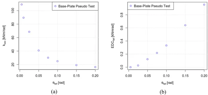
Figure E-3 : Base-plate model subjected to RMI type cyclic loading ... 182
Figure E-4 : Cyclic loading applied to FEM base-plate models ... 182
Figure G-1 : Simplification of a rack moment frame ... 211
Figure G-2 : Comparision of two approximate equations for fundamental period with periods issue from eigenvalue analys ... 213
Figure G-3 : Rack with eccentric loads ... 214
Figure G-4 : Fundamental period with eccentric loads ... 214
Figure G-5 : Rack with beam-level masses ... 214
LIST OF SYMBOLS AND ABBREVIATIONS
a' - Base-plate dimensiona - Base-plate dimension
AF - Adjustment factor
ANSI - American National Standards Institute
B - Damping factor
b - Column width or column depth
c - Base-plate dimension
C - Compressive load
Cd - Deflection amplification factor Cf - Factored compressive load Cr - Compressive resistance CSA - Canadian Standards Association CYX - Quasi-cyclic test X
d - Column width or depth
Dmax - Maximum displacement demand DOF - Degree-of-freedom
E - Modulus of elasticity
Ec - Concrete modulus of elasticity EDC - Energy dissipated per cycle
EDCbpl - Energy dissipated per cycle by a base-plate EDCc - Energy dissipated per cycle by a connector ESF - Equivalent Static Force (Method)
FEMA - Federal Emergency Management Agency
Fy - Yield strength
Fyb - Yield strength of the beam Fyc - Yield strength of the column
h - Column height
hx - Height at level x
Ib - Moment of inertia of the beam Icol - Column moment of inertia IE - Importance factor
j - Number of peaks over which viscous damping is calculated kbpl - Base-plate stiffness
kc - Connector rotational stiffness Ke - Effective stiffness keff,rack - Effective lateral stiffness krack - Lateral stiffness of a rack krack,red. - Rack's reduced lateral stiffness ksec - Secant stiffness
l - Length
Lb - Beam length
LDMA - Large displacement method of analysis Mb - Base-plate yield moment
Mc - Connector moment
Mc,max - Connector peak strength
Mf - Factored moment mi - Mass at level i
mp,bpl - Plastic moment per length of section
Mr - Moment resistance
MRF - Moment resisting frame
MRSA - Modal response spectrum analysis µs - Static friction coefficient
My,bpl - Base-plate yield moment
NBCC - National Building Code of Canada Nbpl - Number of base-plates
Nc - Number of connectors
NEHRP - National Earthquake Hazards Reduction Program NLTH - Non-linear time history
PBX - Pull-back test X
Peff - Effective gravity load load PGA - Peak Ground Acceleration
q - Behaviour factor
QX - Shake table signal X
Rd - Ductility modification factor RF - Filling grade reduction factor RMI - Rack Manufacturer’s Institute Ro - Strength modification factor Rβ - Damping reduction factor Sa - Spectral Acceleration
Sd - Displacement spectrum
Sd,red - Reduced design acceleration spectrum Sd5% - The 5% damped spectral displacement SDOF - Single degree of freedom
SDOF - Single Degree of Freedom
Sdβ - Spectral displacement at β % damping Se - Elastic acceleration spectrum
SF - Scale factor of a ground motion SFc - Strength scaling factor on connector SFRS - Seismic force resisting system
SM1 - MCE spectral acceleration at one second taking into account site effects Sp - Horizontal force factor
T1 - First fundamental period of vibration Teff - Effective fundamental period
Teff,aug. - Effective augmented fundamental period Tn - Fundamental period of vibration
tp - Base-plate thickness ui - The ith decrement of amplitude Vp - Base-shear of the part or portion Vr - Lateral resistance
Vr,min - Minimum lateral resistance
W - Weight of two loaded pallets used in physical tests
WE - External work
Wp - Weight of the part - Beam acceleration
xrel. - Relative displacement of the pallet with respect to the beam
β - Damping ratio
βeff. - Effective or equivalent damping βhyst. - Hysteretic damping
δ - Displacement
δd - Design (or target) displacement δgen - Generalised drift coordinate δmax - Maximum displacement δtop - Peak displacement at the top level
Δ - Drift
Δd - Design (or target) drift Δlim - Drift limit Δavg - Average drift
Δbpl - Drift due to deformation of the base-plate Δcol - Drift due to deformation of the column Δi - Drift at level i
Δtot - Total drift
θb - Base-plate rotation θbpl - Base-plate rotation
θc,max - Maximum rotation capacity of a connector θD - Rotation due to gravity loads
θd,i - Target (or design) displacement at the ith iteration θE - Rotation due to earthquake loads
χ - Stiffness degradation factor Ω0 - Over strength factor
LIST OF APPENDICES
APPENDIX A EXTRACTS FROM ANNEX N ON SEISMIC DESIGN ... 148 APPENDIX B LABORATORY TESTS ………...…………... 154 APPENDIX C FORCE-BASED ANALYSIS AND DESIGN ACCORDING TO ANNEX
N Draft ……….………... 164
APPENDIX D DESCRIPTION OF FEM MODEL OF RACK ……….……... 177 APPENDIX E CYCLIC BASE-PLATE PSEUDO TESTS, FEM BASE-PLATE
MODELS AND VERIFICATION BY YIELD-LINE method ……... 181 APPENDIX F TCL SCRIPTS FOR OPENSEES MODEL ………..…………... 183
APPENDIX G AN APPROXIMATE EQUATION FOR THE FUNDAMENTAL
PERIOD OF A RACK MOMENT Frame……….………... 211 APPENDIX H CYCLE BY CYCLE CURVE MATCHING OF NON-LINEAR
CONNECTORS AND BASE-PLATES ………….………... 215 APPENDIX I GROUND MOTIONS FOR TIME HISTORY ANALYSES ……... 248
CHAPTER 1 INTRODUCTION
Problem Under Study
1.1
Racks are ostensibly simple, economical structures, designed very efficiently to resist the gravity loads of pallets stacked with merchandise. Collapse of racks has been observed in several recent earthquakes: [1], [2], [3], [4], [5], [6]. In selective racks, the most widely used type of rack structure, the “cross-aisle ” direction is commonly composed of braced-frames, while the long rows of the “down-aisle” direction are typically composed of frames with beams that can be clipped into or bolted onto the columns. This allows rapid erection and reconfiguration as well as facilitating swap-out of damaged components.
Figure 1-1: Typical storage rack [7].
By default, the seismic force resisting system (SFRS) in the down-aisle direction is a semi-rigid frame where the beam-column connectors act as the capacitive fuse element, instead of weak beams as would be the case in a building’s rigid moments frames. The principal structural components controlling inelastic seismic response are the beam-column connections and the base-plates. Manufacturers often produce proprietary connectors and base-plates, composed of coldform-sections, channels, HSS, or various combinations of rolled and cold-form sections as shown in Figure 1-2. Their common link is that their cyclic moment-rotation behaviour is ductile and highly non-linear, comprising multiple slopes of stiffness and pronounced pinching.
Figure 1-2: A non-exhaustive sample of available beam-column connections: Clockwise from top-left a bolt-on connector attached to a hot-rolled beam [8], a cold-form column with “tear-drop” clip-in connection [9], a similar cold-form column with another model of connector [10],
“redi-rack” type columns and connectors with rolled-beams [11], cold-form and rolled-beams connected to rolled-column via a bolt-on connector [12], HSS columns with bolt-on connectors
attached to channel beams [13].
Force based methods of seismic design are particularly difficult to apply to racks in part because proscriptive ductility and overstrength factors are a blunt tool considering the variability of rack connectors and more importantly because of the problem of fixing an appropriate stiffness to derive fundamental period and hence spectral accelerations. Initial stiffness is maintained over a small range of the useful rotation range of a connector. Without resorting to some sort of iterative process to find matching strength and stiffness values, strength and stiffness will be incoherent as will be inelastic displacements.
Until recently Canadian codes have provided sparse guidance on the seismic design of racks through the CSA A344-05 (reaffirmed 2011) which references the 1995 edition of the National Building Code of Canada in terms of seismic design. The forthcoming edition of CSA S16-14 will contain Annex N, treating the design of rack structures and specific guidelines for seismic design consistent with the 2015 edition of the NBCC. This annex has adopted ductility modification factors, Rd of 2.0 and 1.5 for rack frames and braced-frames respectively (consistent with findings by [14]) which will result in significantly increased design loads as compared with the A344-05. A displacement-based method for semi-rigid rack moment frames, subject to height limitations in addition to minimum lateral strength requirements, has been proposed in light of several promising studies [15], [16] and a similar method proposed in the American standard FEMA 460 and the European standard NBN EN 16681:2016.
Displacement-based methods promise to adapt well to the unique challenges of designing the semi-rigid moment frame to resist seismic loads by taking into account the stiffness and energy dissipation qualities of specific connectors. However the method as typically applied to rack semi-rigid frames depends on several important assumptions which have yet to face sufficient scrutiny.
Copious and uniformly produced information exists (though is often difficult to obtain) regarding the cyclic behaviour of the beam-column connectors thanks to the RMI qualification procedures to which many manufacturer’s subject their products. Since torsion is generally not important in rack response, the semi-rigid frame may be modelled as planar structure. This, in combination with the fact that in a well designed racks the columns and beams remain elastic, makes racks particularly amenable to modelling with a concentrated plasticity model.
Goals of Study
1.2
This project aims to aide in the development and validation of seismic design provisions put forward in the proposed Annex N of the CSA S16. The focus is on the validation of a displacement-based design method but includes investigations comparisons and propositions for the equivalent static force method. In specific, this project aims to:
- Determine whether displacement-based design is a satisfactory method for designing semi-rigid rack moment frames to resist collapse during earthquakes. To this end:
- Produce a robust finite element model capable of predicting the response of racks with a variety connectors and geometries,
- Validate that the finite element model can accurately predict response in comparison to a simple test case,
- Verify the hypotheses underpinning the application of displacement base design to racks through physical tests and numerical tests,
- Test the feasibility of Annex N by designing a series of prototype racks according its provisions,
- Through a series of non-linear time history analysis on prototype racks, evaluate the safety of the code provisions and propose limits and rectifications,
- Develop knowledge on the seismic response of base-plates, beam-column connectors and pallet sliding,
- Compare force-based design and displacement-based design,
- Produce recommendations to amend the seismic design provisions in Annex N and for further studies.
Methodology
1.3
Following the review of relevant literature and identification of hypotheses and conjectures influencing the applicability of based design, a proposition for a displacement-based design method with direct incorporation of connector unit tests and taking into account P-delta effects was made.
A series of physical tests on 12 specimens of a 1-level, 1-bay cold-formed rack were performed to develop knowledge on the seismic response of racks and generate data for the development and validation of reliable numerical models. The test program included: three quasi-static tests, two pull-back tests and seven seismic tests. The specimens included some with stock base-plates and some with pinned bases. Eastern and western records were scaled to produce a desired level of displacement as predicted by DBD and by preliminary FEM models calibrated from the initial quasi-static and pull-back tests. An attempt was made to induce resonance with a number of specimens following seismic testing.
Finite element models were developed in OpenSees and validated/calibrated against shake table test data and independent qualification tests of the beam-column connectors. These models accounted for yielding in beam-column connectors and base-plates as well as pallet sliding. To generalise the finite element model to take into account the various combinations of hot-rolled and cold-formed members, the model was expanded to incorporate distributed yielding columns allowing for in-plane buckling, concentrated yielding beams, plastic base-plates with compression dependant strength and stiffness.
A number of multi-bay, multi-level prototype racks were designed according to Annex N. The designed racks were subjected to non-linear time history analysis with a large set of representative ground motions for eastern and western Canada. The results of these analyses were used to assess the safety of Annex N provisions for displacement-based seismic design.
Organisation of the thesis
1.4
This thesis is presented in six sections: Chapter 2 gives a review of literature including a general overview of the seismic response of rack moment-frames in §2.1, followed by a summary of world-wide design standards in §2.2, which leads to a detailed review of displacement-based design methods applied to rack moment frames in §2.4 and finishes with summaries of research related to the principal quandaries in rack moment-frame design in §2.4. Chapter 3 reports the results of a series of experiments on a full-scale 1-bay, 1-level rack moment-frame and compares the results with a numerical model developed from these tests. Comparisons of the 1-bay, 1-level configuration are followed by example numerical trials on several multi-level, multi-bay coldform rack models. Chapter 4 presents the application of displacement-based design to a number of multi-level, multi-bay hot-rolled racks containing various connectors and compares their design to non-linear time history analysis. The specifics of the method are outlines in §4.2. In §4.3 several racks are designed and analysed under Annex provisions. The results of the first in a series of non-linear time history analyses are presented in §4.5. Chapter 5 concludes the project and gives a number of recommendations.
CHAPTER 2 LITERATURE REVIEW
Seismic response of rack moment frames
2.1
In 1979 Krawinkler conducted a number static and dynamic tests of rack components and full-size racks [17]. The goal was to determine the governing parameters for rack seismic design which had previously received little study. The ensuing report outlined many of the guiding observations that inform the study and design of racks today, namely:
seismic response is governed by weak pinched connections between beams and columns and by connections at the base,
connectors and base-plates can be represented as rotational springs the properties of which should be determined by experimental component tests,
potential for energy dissipation in the moment frame direction is much greater than in the braced-frame direction,
columns must be properly designed such that P/Pcr ratios are small such that instability is eliminated as a limit state,
P-delta is very important in the moment frame direction and must be considered in analysis.
This study was closely followed by Chen [18] who conducted shake-table tests on full-scale 3-level, 2-bay racks and compared results to a computer model using elastic beams and columns and a bilinear rule in the beam-column connections. Results from these experiments confirmed Krawlinker’s observations. In particular Chen observes that the damping in the moment-frame direction was high (from 3% to 9%) in part do to the loose connection of the beams to columns and early yielding of the connectors and that amplification of story shear due to P-delta was considerable. By adjusting connection stiffness, the computer model used predicted drift well although excursions past the yield point of the connectors were limited. It is suggested that a rack can be adequately modelled by using a linear rotational spring and adjusting damping.
Existing standards on rack seismic design
2.2
2.2.1 Canada
The Canadian standard specific to rack design, the CSA A344.2-05 Standard for the design and construction of steel storage racks, stipulates that racks should be designed to withstand seismic loads §8.2.1 (b) and gives a number of modifications to Part 4 of the NBCC [19] which are largely informed by RMI standards (see 2.2.2):
Fundamental period should not be determined with the approximate equations given in the NBCC and are limited 4 s in the moment frame direction and 2 s the braced frame direction,
Design can be carried out following the method for multi-story buildings or by the methods given for parts and portions,
Ductility and strength modification factor Rd and Ro are left to the discretion of the engineer,
Seismic weight can be reduced to account for probable loading, load damping up to i.e. sliding (up to 60%), but if this is not to be accounted for the seismic weight is 80% of the maximum design load,
The concentrated load, Ft, which is typically added to reproduce higher mode effect need not be applied,
Masses a the first level may be neglected if the beam is less than 300 mm above the floor in seismic weight.
The NBCC does not specifically mention steel storage racks. As such, they may be treated as multi-story buildings or according to §4.1.8.18. Elements of Structures, Non-structural Components and Equipment which gives deflection limits. Non-structural components must be able to accommodate base shear calculated:
and deflections caused by this shear.Where Sp is the horizontal force factor for part or portion of a building and its anchorage determined from Table 4.1.8.18. according to the non-structural component considered. Racks would either be considered numbers 21 or 22 - Flexible components with ductile or non-ductile material and connections.
If a rack with hot-rolled sections is to be designed as a multi-story building its seismic design would fall under Chapter 27 of CSA S16-09 which “may be applied to structures provided that the structure includes a clearly defined seismic-force-resisting system and that a level of safety and seismic performance comparable to that required by Clause 27 for building structures” [20]. While the moment frames and braced frames of racking systems appear similar to MRFs and CBFs they have different failure modes and thus their ductility modification factors should not apply. Conventional construction uses Rd = 1.5 and Ro = 1.3.
Work by Alam & Haque, who derived ductility and overstrenghth factors in a Canadian context, [14] suggests that these values are conservative. Based on pushover analysis and incremental dynamic analysis of 4, 6, 8 and 10 story racks it is observed that Rd decreases as overall height increases from a high of 2.76 to a low of 1.89. Racks designed using this ductility factor were subjected to non-linear time history analyses and found to have acceptable performance.
Currently an Annex to CSA-S16 is under development. In terms of seismic design, this standard aims to formalize capacity seismic design for racks and includes both provisions for force-based methods and displacement-based methods of design.
2.2.2 USA
The following documents govern the seismic design of racks in the USA:
The NEHRP Recommended Seismic Provisions for New Buildings and Other Structures (racks are designated as Non-Building Structures) gives rack specific force modification factors, over strength factors and deflection modification factors as well as direction as to which loading conditions must be considered and how seismic weight is calculated.
The RMI standards designated ANSI MH16.1- of which the 2012 edition is the latest revision and which are referenced by the NEHRP guidelines gives detailed instruction for testing of beam-column connections, calculation of connection rotation capacity, summarized rack specific design
equations for the calculation of base-shear, distribution of forces and calculation of fundamental period.
FEMA 460 Seismic Considerations for Steel Storage Racks published in 2004 is an extensive design guide based upon RMI standards (up until ANSI MH16.1-2002). It gives not only a historical overview of rack design and research but specific recommendations for force-based and displacement based design of rack moment frames. The RMI standard and FEMA 460 underpin many codes used worldwide.
The equivalent static force method described in FEMA 460 uses an R factor in the moment frame direction of 6 in conjunction with an over strength factor Ω0 of 3 and and a deflection amplification factor, Cd, of 5.5. It is noted that these values are derived loosely from Chen [21] and from NEHRP recommendations for SFRS used in structures similar to buildings and notes that their pertinence as applied to rack structures is debateable. Base-shear is calculated considering 67% of the pallet weight. When distributing base shear as equivalent static forces over the height of the rack, a modified equation is used which accounts for beams placed very close to the floor and for racks with periods longer than 2.5 s. It is noted that NEHRP recommends that at least 5% drift must be assumed for the moment-frame.
Because the stiffness of the rack is dependant on assumed displacement, FEMA 460 recommends an iterative process for determining the fundamental period such that “that when the design base shear is applied to a down-aisle model of the storage rack, the moment determined for the beam-moment connections is consistent with the connection stiffness” [22] or by using a rotational spring constant determined from connection tests outlines in the RMI standard and an analytical equation or other mechanical methods.
Little guidance is given in FEMA 460 on how to account for P-delta effects in force based methods other than to state that they are important in the moment frame direction.
FEMA 460 also proposes a displacement-based method for rack seismic design, but cautions that much of the data needed is still under development. This method is based primarily on [15] which is described in detail in §2.3.
2.2.3 Europe
A wide ranging project entitled SEISRACKS has been undertaken by la Fédération Européenne de la Manutention. The project culminated in a report entitled “Storage Racks in Seismic Areas” which details a number of research projects based around component tests, pallet sliding (see §2.4.3 and this section), full-scale pushover and dynamic tests of multi-level, multi-bay racks and numerical modelling of racks. With recommendations made by the SEISRACKS report, the standard entitled EN 16681: Steel static storage systems - Adjustable pallet racking systems - Principles for seismic design was published in 2016. EN 16681 supports three methods of analysis according to the sensitivity of the rack to interstory drift, , and according to which behaviour factor, , the designer wishes to use. The behaviour factor is used to reduce the elastic acceleration spectrum in recognition of (among other factors) ductility of the structural system. For 2 (low dissipative structures) an equivalent static force method (LFMA) or modal response spectrum analysis (MRSA) is mandated; for 2 (high dissipative structure) when the rack is deemed sensitive to interstory drifts, a non-linear time history analysis is necessary. To design the rack moment frame as a high dissipative structure, the beam-column connectors must adhere to certain energy dissipation criteria characterised by cyclic tests and the effect of connector deformations on the global drift must taken into account by a mandated non-linear analysis method.
The main innovation in EN 16681 brought about by the extensive investigations into the characteristics of pallet sliding (see details in §2.4.3) by the SEISRACKS project is the inclusion of a material and warehouse specific friction coefficient, , (given in the standard) through the,
, factor that is used to calculate reduced design acceleration spectrum, , :
, (2-2)
where:
0.4; ⁄ 0.2 (2-3)
is the ordinate of an elastic acceleration spectrum with 3% viscous damping. The second coefficient, , accounts for “other phenomena typical of the dynamic behaviour of racking structures under seismic actions that are not included in the mathematical approach presented in
[the code], but that are observed on racks that have suffered earthquakes, and from tests performed on shaking tables” [23]:
1 1.5⁄ 0.667 (2-4)
EN 16681 includes a pallet weight modification factor, , used to reduce the seismic weight for “damping inside the palletized goods” [24]. varies between 0.7 and 1.0 depending on the type of goods to be loaded onto the rack. The SEISRACKS project emitted the following commentary regarding the use of this factor:
“Such a source of energy dissipation would be possible only if the frequencies of the stored goods are tuned on the frequency of the structure. This is very unlikely according to the respective range of frequencies observed during the SEISRACKS project. Natural frequencies of the racks are rather low (between 0.25 and 1 Hz), while the few values of frequencies obtained for merchandise are significantly higher (between 1.5 and 24 Hz). As long as extensive measurements are not performed to assess the actual dynamic behaviour of a wide range of merchandise, it is recommended not to account for any dissipation in the goods and thus to set ED2 = 1.0”
The standard also accounts for a reduction in the seismic weight of the pallets due to the possibility that not all bays may be full via a client provided filling grade reduction factor,
0.8 (in the moment-frame direction).
EN 16681 also includes a “Large Displacement” method of analysis for “dissipative structure” where q > 2:
When large displacements analysis is performed, the load history shall be defined as follows:
1) the target displacement is first calculated; the target displacement is the maximum horizontal displacement in the direction considered, obtained from MRSA multiplied by the behaviour factor q; the point in which the target displacement is calculated is the target point;
2) the pattern of horizontal forces shall be determined using a distribution matching the modal shape of the fundamental mode in each of the two principal directions;
3) the vertical loads shall be first applied to the structure, then the horizontal forces shall be incremented until the target point reaches a displacement equal to 1.1.
The nonlinear behaviour of materials and connections shall be taken into account.
2.2.4 New Zealand
Following recent earthquakes, rack collapses have been documented in [4] (Christchurch quake), [5] (Darfield quake), and [6] (Canterbury quake). As a result, the guide for the Seismic Design of High Level Storage Racking Systems with Public Access [25] (which is mainly based on a survey of RMI standards adapted to the New Zealand context) was revised. Most revisions pertained to operation of the racks, but the revision called into question the reduction of seismic weight by the factor of 0.67 for sliding as well as the reduction of seismic weight by 0.8, in the moment frame direction, for the probability that the rack would be fully loaded. The authors found that in the case of commerical systems (where pallets are more closely spaced and fully loaded) theses factors were too small [26].
Existing applications of DBD to racks
2.3
The displacement-based method proposed by FEMA 460 was developed in [15] along with an equation for the fundamental period of simple uniform-level, uniform-bay racks. The method supposes that:
The same connectors are used at each beam-column joint, Bay height and width are uniform,
Equal rotations are experienced by all connectors and base-plates, which are the only elements undergoing inelastic deformation.
Assuming known connector moment-rotation curves, the rack can be transformed, under these hypotheses, into a SDOF.
Since the connectors are the capacitive fuse element to be designed in a rack, the design is said to be adequate when the maximum rotation capacity of the connector (more generally termed the target rotation), , , is equal to the rotation demand placed on the connector, . Thus the first step of design is to determine from the experimental moment-rotation curve which can then be used to find the rotational stiffness of the connector, . The fundamental period, , function of beam and column inertias, pallet mass and connector stiffness is ascertained. To find
site specific 5% damped spectral acceleration data must be adjusted to account for damping, converted to displacements and then to rotations. Filiatrault uses the following equation from NEHRP provisions with a damping factor, , issue from the same provisions and dependant on PGA and the viscous damping ratio needed to match the displacement of elastic models to shake table results in [27]:
4 (2-5)
where is gravity acceleration, is the MCE spectral acceleration at one second taking into account site effects. The displacement, , is then augmented to the maximum displacement demand, , by applying a factor to account for P-delta, the equation for which is developped in [15]. Finally the displacement, , is transformed into rotation using the equal rotations assumption:
0.72 (2-6)
The authors note that experimental beam-column connector data is crucial to determine and .
If, as first noted by Krawinkler and subsequently reiterated by many researchers, damping is largely dependant on the loose connection and yielding of connectors, full-scale shake-table tests would also presumably be necessary to choose appropriate rack/connector specific damping ratios. A method that would obviate the need for these large and expensive tests is proposed in [16] where the energy dissipated (and hence damping) is found by subjecting a numerical model of the frame, with connector elements calibrated from test data to a cyclic protocol. The authors apply displacement-based design in a Canadian context and find that, although non-linear time history analysis gave displacements higher than predictions in some instances, the method is safe. This design was carried-out without consideration of P-delta.
Design quandaries
2.4
2.4.1 Lateral stiffness
Although force-based methods typically rely on elastic stiffness, for racks appropriate connector stiffness must be chosen that takes into account the quick yielding of these components. As mentioned in §2.2.2 the RMI recommends an iterative approach to find values of stiffness coherent with rotation and strength values. [28] performed several shake table tests of a cold-form racks to determine the natural period and connector stiffness and give recommendations of the best ways of testing properties. [29] developed analytical equations for finding displacements and rotations in racks with semi-rigid connections subject to lateral loads and including P-delta, and compared analytical equations and found that correspondence was good with eigenvalue analysis. [30] proposed a way to determine fundamental period by including warping (of cold-formed open-section columns) in the stiffness matrix and finds that the approach proposed by FEMA 460 is unsatisfactory. The authors also proposes a coefficient for second order effects to be included in the calculation of the fundamental period.
2.4.2 Base plate stiffness and energy dissipation capacity
Rack base-plates form semi-rigid connections, are typically welded or bolted to columns and bolted into concrete floors. Some recent studies [31] [32] have explored their influence on response in the braced-frame direction and have explored methods for determining strength and stiffness [33], however much less data is available on the cyclic response of base-plate in the moment-frame, although their important effect on seismic response has been noted [31], [32], [33] & [24]. Consensus has not been reached as to the best method of determining base-plate moment-rotation characteristics whether experimentally or analytically. This is in part due to variation in base-plate design between manufacturers and also to the difficulty of performing small experimental component tests like those widely performed on beam-column connectors. As a result, most tests available are non-cyclic. Response of the base-plate may be function of: yielding of the plate (thickness of the plate, bolt-layout, geometry of the plate, width and depth of the column), interaction with the concrete slab, pull-out of the bolts and applied compression [34].
The FEM recommends the use of the testing procedure outlined in EN 15512 to evaluate cyclic response of base-plates. This method, illustrated in Figure 2-1, has been discussed and modified by Gilbert and Rasmussen to avoid “catastrophic failure” during testing [32].
Figure 2-1: Base-plate testing assembly as recommended by the FEM and discussed in [32]. The RMI proposes an analytical approach to determining base-plate stiffness as a function of column width, , and depth, , as well as the concrete slab stiffness, :
1
12 (2-7)
Modifications to this equation have been proposed by Sarawit in function of the base-plate form [34], who considers four different geometries of base-plate.
2.4.3 Pallet sliding, sloshing & shedding
One important way that racks differ from building structures is that the structural self-weight is negligible in comparison to live load. Live load, composed of pallets and merchandise, is not fixed to beams and can become free to slide on, collide with and fall from racks during earthquakes. This creates difficulties for the application of both force-based and displacement-based methods because the participating mass of the structure can change during an earthquake
and thus also its fundamental period. Mass sliding is often taken into account by reduction of the seismic weight: in [35], [23], [36] and the forth-coming Annex N [20].
The researchers involved in the SEISRACKS project have carried-out the most wide ranging investigation of pallet-beam friction coefficients and pallet-rack-sliding interaction.
Parameters investigated: pallet and beam material, mass, mass eccentricity, acceleration and frequency,
For dry pallets µ varies between approx. 0.2 and 0.6 in cross-aisle direction (with plastic pallets being the most slippery) and between 0.1 and 0.6 in the down-aisle direction, Applied mass is less influential than other parameters on µ,
In cross aisle direction first slippage can occur between 0.15g and 0.35g while in down-aisle direction first slippage occurs around 0.3g to 0.6g. Dynamic slippage depends somewhat on frequency and on materials. Plastic pallets were not investigated in the dynamic portion of testing.
In [37] analytical equations and a finite element friction model is developed. This model was used in conjunction with the experimental results of the SEISRACKS project. In [38] a simple FEM rack with stick-slip pallets is subjected to a single ground motion with peak accelerations around 0.5 g. It is found that inertial forces are reduced by sliding, force decreases in function of µ are presented. The largest pallet sliding displacement is about 50 mm.
Reference [39] also presents the development of equations for the stick, slip, flight, impact of an SDOF pallet by using a series of springs. Analytical equations are followed by a series of numerical tests and experiments using inclined racks with the goal of preventing shedding of merchandise.
In [40] 4-story finite element model of a cross-aisle rack is subject to 10 California ground motions with PGA around 1g. Peak acceleration of the beam-levels is significantly reduced with the use of added damping and sliding pallets. For stiff merchandise sliding effects drastically drastically peak beam-level acceleration, for flexible merchandise less-so.
2.4.4 Scaling of spectra for damping
Acceleration spectra are given by the NBCC for 5% damping. Displacement-based design requires displacement spectra (see 2.3) at many and larger values of damping. Response of a damped structure depends on quake duration, frequency content, site conditions, distance from epicentre and magnitude. An exhaustive survey and comparison of damping scaling factors is given in [41]. The NBCC 2010 does not give recommendations for scaling factors, but the Canadian Bridge design code suggests the following equation:
0.1 ⁄ 0.05 . (2-8)
2.4.5 P-delta
Two main approaches have been proposed to account for P-delta effects during displacement-based design. The first is a general (not rack specific) approach described in [42] which proposes a strength enhancement to lift the force-deformation relationship of a structure analysed with P-delta up to the strength level of a structure analysed without P-P-delta. The general concept of this approach is illustrated in Figure 2-2.
Figure 2-2: Accounting for P-delta according to [43].
In Figure 2-2 (c) the effective stiffness Ke (1) is adjusted to take into account displacements that include P-delta. Strength must be increased to achieve acceptable displacements Ke (2), but strength ought to be increased such that the target displacement matchs the displacement without