HAL Id: hal-01006907
https://hal.archives-ouvertes.fr/hal-01006907
Submitted on 29 Sep 2017
HAL is a multi-disciplinary open access
archive for the deposit and dissemination of
sci-entific research documents, whether they are
pub-lished or not. The documents may come from
teaching and research institutions in France or
abroad, or from public or private research centers.
L’archive ouverte pluridisciplinaire HAL, est
destinée au dépôt et à la diffusion de documents
scientifiques de niveau recherche, publiés ou non,
émanant des établissements d’enseignement et de
recherche français ou étrangers, des laboratoires
publics ou privés.
Friction stir diffusion bonding of dissimilar metals
Marion Girard, Bertrand Huneau, Cécile Genevois, Xavier Sauvage,
Guillaume Racineux
To cite this version:
Marion Girard, Bertrand Huneau, Cécile Genevois, Xavier Sauvage, Guillaume Racineux.
Fric-tion stir diffusion bonding of dissimilar metals.
Science and Technology of Welding and
Joining, Maney Publishing, 2010, Friction stir welding and processing, 15 (8), pp.661-665.
�10.1179/136217110X12720264008475�. �hal-01006907�
Friction stir diffusion bonding of dissimilar
metals
M. Girard
1, B. Huneau*
1, C. Genevois
2, X. Sauvage
2and G. Racineux
1This paper reports on a new method based on the friction stir welding process to join dissimilar
metals in butt joint configuration. Two different systems were considered: AA1050 H16 aluminium/
ASTM A284 steel and AA1050 H16/UNS C12200 H01 copper. The unthreaded steel tool pin was
positioned in the aluminium plate so that it was tangential to the opposing metal. Bonding was
accompanied by interfacial chemical reactions with no significant mechanical mixing. This new
solid state welding process is called friction stir diffusion bonding. Room temperature cross-weld
tensile strengths up to 82 MPa were obtained for both metal combinations. Microstructure
characterisation suggested that higher joint strengths were associated with thinner, ,1 mm thick
intermetallic reaction layers at joint interfaces.
Keywords: Intermetallics, Aluminium, Steel, Copper, Diffusion, Friction stir welding
Introduction
Friction stir welding (FSW) of dissimilar metals and alloys has been investigated for approximately 10 years. Despite the numerous published works, no standard method exists especially in the case of the butt joint configuration. Indeed, for this configuration the welding parameters are not only the rotational speed and the traverse speed but also the pin position with regard to the interface between the plates and the choice of the plate to be in the advancing side. These parameters are highly dependent on the metallic couple investigated.
Two different situations may be considered. The first consists in joining two different alloys of the same metals, for example two aluminium alloys,1–3 or two different alloys having relatively close properties, such as aluminium and magnesium alloys.4–7In all these studies, the pin of the tool is positioned at the interface between the two plates to be welded, which means that both alloys are intimately mixed. The cross-sections reveal defect free welds and the mechanical properties are relatively good. Some authors also reported the dissim-ilar welding of pure iron to pure nickel.8In this case the pin was also placed at the interface between the two plates to be welded.
The second situation is related to dissimilar welding of metallic alloys with very different properties. In the following, the authors consider two systems: aluminium/ steel and aluminium/copper.
In the case of dissimilar welding of aluminium alloys to structural steels, a few studies have been published since 2003.9–13 All these studies showed that the best
tensile strength results are obtained with the aluminium plate in the retreating side, but there is no common agreement concerning the position of the pin with regard to the interface between the two plates. Watanabe et al. investigated different positions of the pin relatively to the interface and showed that the best mechanical strength of the joint was obtained when the pin was mainly positioned in the aluminium plate with a 0?2 mm lateral shift towards the steel plate.9,10 These experi-ments were performed with a tool made of hard steel, which can be a problem if one considers the wear of the tool. Fukumoto et al. found the same kind of results even if they suggested a smaller penetration in the steel plate of 0?1 mm.12 On the other hand, Kovacevic and co-workers tried to position the pin at the interface, leading to a stronger mixing of the two alloys. In their first published work using this configuration, the steel tool was broken.11It also appeared that aluminium was partially melted during the process, resulting in a large amount of intermetallic compounds (IMCs). In a second study, they managed to prevent the breakage of the tool by using a special W–Re tool, which is very expensive.14 Concerning the dissimilar FSW of Al alloys to copper, the mixing of the two materials is expected to be easier than that of Al alloys with steels. However, as reported for the joining of 6xxx aluminium alloys to copper, defect free friction stir welds are not easy to achieve. There is usually a void formation throughout the weld.1,15 Nevertheless, most of studies about the FSW of Al alloys to copper reported a configuration where both metals were mixed.1,15–18 Savolainen et al., who obtained some void free welds, investigated the influence of the position of the pin with regard to the interface and showed that the best mechanical properties were
1Institut de Recherche en Ge´nie Civil et Me´canique, Ecole Centrale de
Nantes, Universite´ de Nantes, CNRS (UMR 6183), 1 rue de la Noe¨ - BP 92101, 44321 Nantes, France
2University of Rouen, Groupe de Physique des Mate´riaux, CNRS (UMR
6634), Avenue de l’Universite´ - BP 12, 76801 Saint-Etienne du Rouvray, France
obtained when the 6 mm diameter pin was shifted of 1?5 mm from the centreline towards the copper plate.18 Therefore, obviously, a general and reliable method to perform sound friction stir welds of dissimilar metal has not yet been established so far. This paper presents a method called friction stir diffusion bonding (FSDB) designed to produce defect free joints of dissimilar metals. The approach that is proposed minimises the formation of deleterious IMC. The present study reports on the application of FSDB to aluminium/steel and aluminium/copper systems.
Materials and procedure
Three materials were considered in the present study: an AA 1050 H16, a structural steel labelled S235 (equiva-lent to ASTM A284) and a commercially pure copper labelled Cub1 H11 (equivalent to UNS C12200 H01). All plates are 4 mm thick. The edge of the steel plate is previously machined whereas the aluminium and copper plates are rough edge.
Friction stir welding experiments were performed using a Computed Numerically Command (CNC) milling machine controlled in position with a gantry configuration. The tool has a 20 mm diameter shoulder and an unthreaded cylindrical 6?5 mm diameter pin that is y4 mm in length. The rotational speed is y900 rev min21
and the traverse speed is 20 or 100 mm min21. These parameters are sufficient to ensure an intimate contact between the two materials (no porosity), which is essential for diffusion bonding. In all cases:
(i) the welding direction coincided with the rolling direction of the material plates
(ii) the aluminium was positioned in the retreating side
(iii) the tool pin was positioned in the aluminium plate so that it was tangential to the steel or copper plate with a precision of ¡0?05 mm (Fig. 1a and b).
The plates are clamped on top of a backing plate and held together with powerful fixtures as shown in Fig. 1c. Microstructures were characterised using scanning electron microscopy (SEM) and transmission electron microscopy (TEM). The SEM specimens were mounted and mechanically polished before observation. The TEM specimens were prepared in the cross-section of the welds: 3 mm discs were punched out and mechani-cally thinned down to 50 mm in thickness. Electron transparency of foils was achieved by ion milling. Observations were performed with microscopes operat-ing at 200 kV (JEOL 2000FX and JEOL 2100, JEOL Ltd, Tokyo, Japan).
The mechanical properties of the welds were char-acterised by tensile tests performed on transverse samples at room temperature and at 1 mm min21.
Results and discussion
Al/steel welds
Macrosections of the Al/steel joints welded with a traverse speed of 20 mm min21 do not exhibit any visible defects like macrocracks or voids (Fig. 2). The macroscopic interface between the steel and the alumi-nium plate looks sharp without any significant rough-ness or particles. There is no visible mixing of the two materials. This feature is attributed to the specific experimental conditions since the pin of the tool was fully located in the aluminium plate.
However, a careful observation of the interface in the SEM clearly reveals an IMC layer (Fig. 3). One should note that depending on the location in the weld this reactive layer exhibits very different features. On the top of the weld (Fig. 3a), it isy3 mm thick and some cracks appear. The EDX analyses revealed that the interfacial layer is composed of two intermetallics, namely Al3Fe
and Al5Fe2(profiles not shown here). In the bottom of
the weld, the IMC layer is one order of magnitude thinner, ,0?5 mm (Fig. 3c), quite regular and crack free. It is unfortunately too thin for any quantitative EDX analysis. The transition from the bottom to the top structure is not continuous and regular. Indeed, in the middle of the weld, the IMC layer exhibits both a thin layer at the interface and larger particles a few micrometres in diameter (Fig. 3b). These particles are similar to the intermetallic phases identified in the top of the weld (EDX data not shown here).
The presence of the two IMCs Al3Fe and Al5Fe2 is
consistent with some data from the literature concerning
a schematic representation; b picture taken during FSDB of aluminium to steel; c general view of experimental setting 1 Typical configuration of FSDB process
2 Top view and cross-section of Al/steel joint (20 mm min21)
solid state reaction between Al and Fe.19–21Moreover, Chen et al. recently suggested that in the case of an aluminium/steel friction stir lap joint, the Al3Fe is the
first phase to appear; then it reacts with aluminium to produce Al5Fe2.20 This sequence is supported by the
theoretical work of Pretorius et al. and their so called effective heat of formation model.22
Some Al/steel joints were performed with a higher traverse speed, at 100 mm min21. Considering that heat input will be smaller in this case, the IMC layer is expected to be thinner and free of cracks. The macrosections of the welds (data not shown here) look similar to that obtained with a traverse speed of 20 mm min21 (Fig. 2). There are no visible macro-cracks, voids and even mixing of the two materials at the interface. However, contrary to the joint obtained at 20 mm min21, no IMC layer could be observed in the SEM from the top to the bottom of the weld (Fig. 4a). Thus, the cross-section of the weld was characterised by TEM and a very thin (50–100 nm) and irregular IMC layer was revealed (Fig. 4b). This layer does not continuously cover the interface but seems to be composed of numerous nanoscaled particles that have nucleated at the Al/steel interface. Surprisingly, some particles could also be observed inside the aluminium plate, but at a very short distance of the IMC layer (in a range of 100 to 200 nm).
The results of the mechanical tests performed on Al/ steel welds are summarised in Table 1. Each ultimate tensile strength (UTS) value is an average value from at least two tests. The fracture location and the plastic deformation in the aluminium side are also reported. Complementary tests on the base Al alloy have shown that the UTS is of 138 and 69 MPa after a recrystallisa-tion heat treatment (30 min annealing at 400uC).
Table 1 clearly shows that welds performed with a higher traverse speed (100 mm min21) are stronger. This feature is attributed to the thinnest and crack free IMC layer formed at the interface as revealed by SEM and TEM. The welds performed with a traverse speed of
20 mm min21 exhibit an UTS which is only y40% of the base aluminium. For this configuration, the joints break at the interface with almost any deformation of the aluminium. On the contrary, for the tests performed at 100 mm min21, the fracture occurs after a plastic deformation, regardless where it is located, interface (Fig. 5a) or aluminium (Fig. 5b). When the fracture occurs at the interface, the plastic deformation is smaller than when the fracture occurs in the aluminium. At 100 mm min21, UTS remains lower than the base material one, y60%, since the strain hardening con-tribution is partially lost in the zone affected by the process. Compared with the annealed base aluminium
a top of weld where cracks and large IMC layer appear; b middle of weld where both large particles and thin IMC layer appear; c bottom of weld where only thin layer of IMC appears
3 Secondary electron SEM images showing cross-section of Al/steel weld (20 mm min21) at different positions
a secondary electron SEM image; b TEM bright field image showing thin and irregular IMC layer at interface 4 Cross-sections of Al/steel weld (100 mm min21)
Table 1 Results of tensile tests performed on Al/steel welds
Traverse speed, mm min21 Average UTS, MPa Fracture location Plastic deformation in aluminium side, % % base aluminium UTS % annealed base aluminium UTS
20 55 Interface ,1 40 80
100 80 Interface 2–7 58 116
which is fully recrystallised, the strengths of these joints are greater.
These results suggest that a thin layer is less detrimental than a thicker one, which is consistent with the literature. Indeed, some authors have shown that there is a critical IMC layer size above which the tensile strength of the Al/steel joint quickly decreases, both in the case of FSW23and diffusion bonding.24,25According to these works, the critical size of the IMC layer is between 0?5 and 1?5 mm.
Al/Cu welds
Similar to the Al/steel system, macrosections of the Al/ Cu joint welded with a traverse speed of 100 mm min21 do not exhibit any visible defects such as macrocracks or voids (Fig. 6). The macroscopic interface between the aluminium alloy and the copper plates looks sharp without any significant roughness or particles. There is also no visible mixing of the two materials. As in the Al/ steel system, this feature is due to the position of the pin that was fully located in the aluminium.
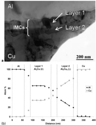
Similarly to the Al/steel, the dissimilar materials are bonded by a thin layer of IMC (Fig. 7a), but under similar welding conditions (traverse speed 100 mm min21) this layer is thicker (y200 versus 100 nm). Within the interface
region, two layers of nanoscaled IMC grains are clearly exhibited. On the Al (respectively Cu) side, the mean grain size of IMC isy120 nm (respectively 80 nm). The TEM observations were carried out in various locations of the weld. It clearly appears that the IMC bonding layer is not everywhere as regular as shown on the bright field image of the Fig. 7a, it is more fragmented in the bottom of the weld. Using EDX analysis, the mean chemical compo-fosition of these two nanolayers was measured (Fig. 7b). Near the aluminium side, it contains about 64 at-%Al and 36 at-%Cu, corresponding to the Al2Cu (h) phase. One
should note that, considering the effective heat of formation model22and as shown by Moreno et al.,26this phase is expected to nucleate first. On the copper side, the copper concentration of the second nanolayer is in a range of 65 to 75 at-% corresponding to the Al4Cu9(c) phase.
The EDX line scan shows a larger composition gradient in this later phase compared to the Al2Cu, in agreement with
the equilibrium phase diagram. It has been reported in the literature that the AlCu (g) phase could also nucleate during the solid state reaction between aluminium and copper.16,27 In the present case, nanograins of this IMC may be located between the Al4Cu9 (c) and Al2Cu (h)
layers but they cannot be pointed out without ambiguity owing to possible grain overlaps and lack of spatial resolution of the EDX analysis.
The strength of the welds was tested in tension (Table 2). Although the fracture occurred at the Al/Cu
6 Top view and cross-section of Al/Cu joint (20 mm min21)
showing defect free weld
Table 2 Results of tensile tests performed on Al/copper welds Traverse speed, mm min21 Average UTS, MPa Fracture location Plastic deformation in aluminium side, % % base aluminium UTS % annealed base aluminium UTS
100 82 Interface 4–5 60 118
a fracture at interface; b fracture in aluminium plate 5 Macrosections of two Al/steel joints (100 mm min21)
after tensile tests
7 aTEM bright field image of cross-section of Al/Cu weld showing thin layer of IMC (Al on top) and b EDX profile through IMC layer at Al/Cu interface
interface, the joint failed after a significant plastic deformation in the thermomechanically affected zone of the Al plate, as observed for Al/steel welds obtained for the same traverse speed. Therefore, the UTS of Al/ steel and Al/Cu welds are very similar,y80 MPa, which corresponds approximately to 60% of the base alumi-nium UTS.
Conclusions
The present study leads to the following conclusions: 1. The FSDB process was used to produce defect free joints of dissimilar metals such as Al/steel and Al/Cu, without any mixing of the two materials. This process is based on atomic diffusion which leads to the formation of an IMC layer whose thickness varies from 50 nm to a few micrometres.
2. When the IMC layer remains thin (,1 mm), the UTS of the dissimilar joints reaches 60% of the aluminium alloy one, whatever the fracture occurs in the aluminium or at the interface. In the case of a high heat input, i.e. for the low traverse speed used for the Al/ steel joint, the IMC layer can grow to a few micrometres in thickness. In this case, the large and irregular interface embrittles the joint and reduces its tensile strength to 40% of the aluminium one.
3. In the high heat input Al/steel joint, the IMC layer is composed of Al5Fe2 and Al3Fe, while in the Al/Cu
joint, it is composed of Al2Cu and Al4Cu9.
Acknowledgement
The authors gratefully acknowledge Dr R. Ravelle-Chapuis from JEOL SAS for TEM analyses on the JEOL 2100 microscope.
References
1. L. E. Murr, Y. Li, R. D. Flores, E. A. Trillo and J. C. McClure: Mater. Res. Innov., 1998, 2, 150–163.
2. W. B. Lee, Y. M. Yeon and S. B. Jung: Scr. Mater., 2003, 49, 423–428. 3. P. Cavaliere, E. Cerri and A. Squillace: J. Mater. Sci., 2005, 40,
3669–3676.
4. Y. S. Sato, S. H. C. Park, M. Michiuchi and H. Kokawa: Scr. Mater., 2004, 50, 1233–1236.
5. A. C. Somasekharan and L. E. Murr: Mater. Charact., 2004, 52, 49–64.
6. A. Kostka, R. S. Coelho, J. dos Santos and A. R. Pyzalla: Scr. Mater., 2009, 60, 953–956.
7. R. Zettler: Adv. Eng. Mater., 2006, 8, 415–421.
8. R. Ayer, H. W. Jin, R. R. Mueller, S. Ling and S. Ford: Scr. Mater., 2005, 53, 1383–1387.
9. T. Watanabe, H. Takayama, K. Kimapong and N. Hotta: Mater. Sci. Forum, 2003, 426–432, 4129–4134.
10. T. Watanabe, H. Takayama and A. Yanagisawa: J. Mater. Process. Technol., 2006, 178, 342–349.
11. C. M. Chen and R. Kovacevic: Int. J. Mach. Tools Manuf., 2004, 44, 1205–1214.
12. M. Fukumoto, M. Tsubaki, Y. Shimoda and T. Yasui: Q. J. Jpn Weld. Soc., 2004, 22, 309–314.
13. T. Yasui, Y. Shimoda, M. Tsubaki, T. Ishii and M. Fukumoto: Q. J. Jpn Weld. Soc., 2005, 23, 469–475.
14. V. Soundararajan and R. Kovacevic: Proc. 6th Int. Symp. on ‘Friction stir welding’, Saint-Sauveur, Canada, October 2006, TWI, CD-ROM.
15. M. N. Avettand-Fenoel, R. Taillard, C. Herbelot and A. Imad: Mater. Sci. Forum, 2009, 638–642, 1209–1214.
16. H. Ouyang, E. Yarrapareddy and R. Kovacevic: J. Mater. Process. Technol., 2006, 172, 110–122.
17. P. Liu, Q. Y. Shi, W. Wang, X. Wang and Z. L. Zhang: Mater. Lett., 2008, 62, 4106–4108.
18. K. Savolainen, K. Mononen, T. Saukkonen and H. Ha¨nninen: Proc. 6th Int. Symp. on ‘Friction stir welding’, Saint-Sauveur, Canada, October 2006, TWI, CD-ROM.
19. V. Jindal, V. C. Srivastava, A. Das and R. N. Ghosh: Mater. Lett., 2006, 60, 1758–1761.
20. Y. C. Chen, T. Komazaki, Y. G. Kim, T. Tsumura and K. Nakata: Mater. Chem. Phys., 2008, 111, 375–380.
21. C. Y. Lee, D. H. Choi, Y. M. Yeon and S. B. Jung: Sci. Technol. Weld. Join., 2009, 14, 216–220.
22. R. Pretorius, T. K. Marais and C. C. Theron: Mater. Sci. Eng. R, 1993, R10, 1–83.
23. T. Tanaka, T. Morishige and T. Hirata: Scr. Mater., 2009, 61, 756– 759.
24. A. Hirose, H. Imaeda, M. Kondo and K. F. Kobayashi: Mater. Sci. Forum, 2007, 539–543, 3888–3893.
25. S. Kuroda, K. Saida and K. Nishimoto: Q. J. Jpn Weld. Soc., 1999, 17, 484–489.
26. D. Moreno, J. Garrett and J. D. Embury: Intermetallics, 1999, 7, 1001–1009.
27. W. B. Lee, K. S. Bang and S. B. Jung: J. Alloys Compd, 2005, 390, 212–219.