HAL Id: hal-02179977
https://hal.archives-ouvertes.fr/hal-02179977
Submitted on 12 Jul 2019HAL is a multi-disciplinary open access archive for the deposit and dissemination of sci-entific research documents, whether they are pub-lished or not. The documents may come from teaching and research institutions in France or abroad, or from public or private research centers.
L’archive ouverte pluridisciplinaire HAL, est destinée au dépôt et à la diffusion de documents scientifiques de niveau recherche, publiés ou non, émanant des établissements d’enseignement et de recherche français ou étrangers, des laboratoires publics ou privés.
Design of polymeric capsules for self-healing concrete
Benoit Hilloulin, Kim van Tittelboom, Elke Gruyaert, Nele de Belie, Ahmed
Loukili
To cite this version:
Benoit Hilloulin, Kim van Tittelboom, Elke Gruyaert, Nele de Belie, Ahmed Loukili. Design of polymeric capsules for self-healing concrete. Cement and Concrete Composites, Elsevier, 2015, 55, pp.298-307. �10.1016/j.cemconcomp.2014.09.022�. �hal-02179977�
1
Design of polymeric capsules for self-healing concrete
1
2
Benoit Hilloulina,b*, Kim Van Tittelboomb, Elke Gruyaertb, 3
Nele De Belieb, Ahmed Loukili a 4
a
LUNAM Université, Institut de Recherche en Génie Civil et Mécanique (GeM), UMR-CNRS
5
6183, Ecole Centrale de Nantes, 1 rue de la Noë, 44321 Nantes, France – e-mail:
6
[email protected]; [email protected]
7
b
Magnel Laboratory for Concrete Research, Department of Structural Engineering, Faculty of
8
Engineering, Ghent University, Technologiepark Zwijnaarde 904, B-9052 Ghent, Belgium –
e-9
mail: [email protected], [email protected], [email protected]
10
*
Corresponding author: Tel.: + 33 (0)2 40 37 16 63
11 12
Abstract 13
Up to now, glass capsules, which cannot resist the mixing process of concrete, have 14
been mostly used in lab-scale proof-of-concept to encapsulate polymeric agents in self-15
healing concrete. This study presents the design of polymeric capsules which are able to 16
resist 17
the concrete mixing process and which can break when cracks appear. Three different 18
polymers with a low glass transition temperature Tg have been extruded: Poly(lactic
19
acid) (PLA) (Tg = 59 °C), Polystyrene (PS) (Tg = 102 °C) and
20
Poly(methyl methacrylate/n-butyl methacrylate) (P(MMA/n-BMA)) (Tg = 59 °C). After 21
heating the capsules prior to mixing with other components of the mix, to shift from a 22
brittle state to a rubbery state, their survival ratio considerably increased. Moreover, a 23
part of the capsules, which previously survived the concrete mixing process, broke with 24
crack appearance. Although some optimization is still necessary concerning functional 25
life of encapsulated adhesives, this seems to be a promising route. 26
2
Keywords: Self-healing Concrete, Polymers, Capsules, Mixing, Mortar, Cracks 28
29
1. Introduction 30
31
In concrete structures, cracks often appear due to the limited tensile strength of concrete. 32
These cracks endanger the durability as aggressive substances, dissolved in fluids and 33
gasses, can easily flow inside the matrix and lead to structural failure by reinforcement 34
corrosion. Moreover, cracks are also considered undesirable for aesthetic reasons. Due 35
to regular and planned inspection rounds followed by proper treatments, maintenance 36
costs of concrete structures are quite high nowadays. It has been estimated that, in 37
Europe, around 50 % of the annual construction budget is spent on rehabilitation and 38
repair of the existing structures [1, 2]. 39
Therefore, making self-healing concrete could highly reduce the maintenance costs and 40
improve the durability of concrete structures. Under control, self-healing could be taken 41
into account by designers to meet project owners’ durability expectations, following the 42
‘damage management concept’ introduced by Van der Zwaag in opposition to the actual 43
‘damage prevention principle’ widely used in construction codes [3]. Consequently, 44
service life of structures would increase considerably. 45
Encapsulation of healing agents is a very effective method to obtain complete sealing of 46
the crack with chemical agents, to avoid penetration of aggressive substances and, in 47
some cases to obtain partial regain in mechanical properties which is an important 48
aspect to guarantee the performance during service life (succession of crack formations) 49
[4]. However, up to now, glass capsules have been mostly used [5-11] to store the 50
healing agent. They break upon crack appearance but they cannot resist the concrete 51
mixing process without particular protection (protection by a cement paste bar or a 52
3
metallic wire seem limited [12, 13], only bundling the capsules with a water soluble 53
solution is reported to protect them while mixing in a truck [14]). This can be explained 54
by their brittleness and their dimensions (glass tubes with a wall thickness of 2 mm are 55
able to rupture upon crack formation, 3 mm thick tubes cannot break any more upon 56
crack formation [15]. Survival of the concrete mixing process would facilitate the 57
application of self-healing materials and decrease their price by reducing human work. 58
An evolution towards polymeric encapsulation materials could be the means to adjust 59
capsule properties more easily and to resist the mixing process (as suggested by Dry 60
[16]). Besides glass, some natural fibres [17, 18], gelatine capsules [1], paraffin to 61
enclose water [19], wax [20] and polyurethane [21] have been used. Ceramic, a very 62
brittle material, has also been used by Van Tittelboom [4] who observed a better bond 63
strength than with glass. Spherical capsules can be successfully mixed in concrete [1, 64
20-26] but cylindrical capsules present better chances to break upon crack appearance 65
[13] and release the healing agent more efficiently [27] even if their orientation is still a 66
concern. Polypropylene capsules coated with wax and heated to release the capsules 67
content [8] have been studied to produce capsules able to resist the concrete mixing 68
process. 69
This study explores the development of polymeric capsules that are able to survive the 70
concrete mixing process without any particular protection, and to break upon crack 71
appearance without human intervention. The selected polymers are brittle at room 72
temperature and have a relatively low glass transition temperature. Consequently, their 73
ability to resist the concrete mixing process, when they were heated before mixing and 74
mixed with heated components, was studied. The capsule breakage with crack 75
appearance was measured by the means of three-point-bending tests performed on small 76
mortar specimens. 77
4 78
79
2. Materials and methods 80
2.1 Materials preparation 81
2.1.1 Extrusion of the capsules 82
In order to be able to change easily the mechanical properties of the capsules, polymers 83
with low glass transition temperatures have been selected. Indeed, around their glass 84
transition temperature, the physical properties of polymers change considerably. At first, 85
polymers with a glass transition temperature between 35 °C and 50 °C were sought for. 86
Later, this range was extended until 100 °C to include cheaper and more common 87
materials. On the other hand, specific attention was paid to select polymeric materials 88
with a relatively brittle behaviour at room temperature (low elongation at rupture, 89
relatively high tensile strength). The permeability of the polymers was also taken into 90
account because it may influence the shelf-life of the healing agent embedded inside the 91
polymeric capsules. 92
Finally, three polymers have been selected: 93
- Poly(lactic acid) (PLA) is derived from renewable resources (sugar cane, corn, tapioca) 94
and is biodegradable. It has a low Tg (around 60 °C) and can break at limited elongation
95
(1 to 10 %). PLA is largely used in food industry to replace polystyrene but exhibits a 96
relatively high water-vapour transmission rate [28-31]. No application of PLA in 97
concrete or buildings materials is known by the authors. 98
- Polystyrene (PS) is a common plastic known for its brittleness (elongation at rupture 99
inferior to 2 %) and its good chemical resistance as it is used for food packaging. It is 100
cheap but its Tg comes close to 100 °C. Its permeation properties are relatively good and
5
close to the ones of PLA [32]. Expanded polystyrene is used as aggregate in place of 102
sand and stone in lightweight concrete [33-36]. 103
- Poly(methyl methacrylate/n-butyl methacrylate) (called P(MMA/n-BMA) in this study) 104
with a catalogued Tg of 50 °C. It has been considered in this study because of the
105
brittleness of Poly(Methyl Methacrylate) and the low Tg of P(MMA/n-BMA)(while Tg
106
of pure PMMA is around 105 °C). Although pure PMMA has been compared to 107
concrete because of its brittle behaviour [37] and has been incorporated as a waste 108
material in asphalt mixes, no other application of P(MMA/n-BMA) in civil engineering 109
is known by the authors [38-40]. 110
A laboratory-scale inter-meshing co-rotating twin-screw extruder (MP19TC-25, APV 111
Baker, Newcastle-under-Lyme, UK) with a length over screw diameter ratio (L/D) of 112
25:1 was employed to extrude hollow tubes using a die with an outer hole of diameter 5 113
mm and an inner pin of diameter 3 mm. The temperature settings used during the 114
extrusion process to obtain a good melt without degradation, are presented in Table 1. 115
116
Table 1: Temperature settings (°C) at several locations in the extruder for extrusion of 117
the different thermoplastics. 118
Polymer T1
(breaker plate) T2 T3 T4
T5
(entrance of the barrel)
PLA 135 148 152 150 145
P(MMA/n-BMA) 127 131 130 130 123
PS 178 171 165 160 150
119
Different sizes of tubes were obtained due to different expansion ratios of the polymers. 120
Along the same tube of a length of 1 meter, the thickness and the diameter also varied. 121
Hollow tubes were cut at 5 cm length or 10 cm length for the different tests. Capsules 122
were sorted in different size ranges and their cross section area was measured by means 123
6
of a light microscope. The mean values of the measured sizes are presented in Table 2 124
(standard deviation which was relatively small (maximum 0.2 mm) is not mentioned). 125
As PS capsules had almost all the same dimensions, they were not sorted. Rods were 126
also extruded with dies with holes of 1.8 mm and 4.9 mm to perform dynamic 127
mechanical analysis (DMA). 128
129
Table 2: Approximate dimensions of extruded capsules for the different size ranges 130
(mean values of the outer diameter [mm] and the inner diameter [mm]). 131 Polymer S1 S2 S3 S4 S5 PLA 1.9, 1.1 3.5, 1.8 4.0, 2.1 4.5, 2.6 5.2, 3.2 P(MMA/n-BMA) 6.0, 3.3 6.4, 3.4 6.6, 3.6 6.7, 3.8 6.8, 4.0 PS 7.2, 3.8 132
PLA, P(MMA/n-BMA) and PS have been successfully extruded with a relatively wide 133
range of temperature settings (± 5 °C in values specified in Table 1 can also lead to a 134
successful extrusion) and no sign of degradation. 135
136
2.1.2 Preparation of the mortar samples 137
Bond strength test and three points bending test have been performed to show the 138
interest of polymeric capsules in self-healing concrete. 139
Bond strength tests have been performed in order to ensure that the capsules would not 140
slip in the concrete matrix during crack formation. To measure the bond strength, 5 cm 141
long polymeric tubes filled with epoxy were partially embedded (10 mm) inside mortar 142
samples (W/C = 0.5). 143
Tubes were placed in holes in wooden frames and their position was adjusted before 144
casting of the mortar into cylindrical PVC moulds (diameter 100 mm, height 50 mm) as 145
7
illustrated in Figure 1. After casting, the samples were stored in an air-conditioned room 146
(20 ◦C, 95% RH) and demoulded after 24 hours. Subsequently, they were cured at room 147
temperature (20 ◦C, 60% RH) during 14 days until testing. 148
149
150
Figure 1: Moulds used to prepare the mortar samples with the embedded capsules for 151
the bond strength tests (redrafted after [13]). 152
153
In order to quantify the ability of the capsules to break at the moment of crack formation, 154
mortar specimens containing capsules were prepared. Mortar mixtures consisted of 155
1350 g DIN standard sand, 450 g binder and 180 g water (W/C = 0.4). They were 156
prepared according to the standard NBN EN 196-1 (2005). 157
First, a layer of 10 mm mortar was poured into 40 mm x 40 mm x 160 mm moulds. Two 158
steel reinforcing bars with a diameter of 2 mm were placed on top of the mortar layer to 159
avoid premature failure during crack formation. Two to four capsules were positioned in 160
the middle of the specimen where the crack was presumed to appear as illustrated in 161
Figure 2 before filling the mould completely. 162
8 164
Figure 2: Preparation of mortar prisms with embedded capsules and reinforcement. 165
166
PS, PLA and P(MMA/n-BMA) capsules were placed in the mortar specimens. As 167
illustrated in Table 3, some capsules which survived mixing were embedded, as well as 168
‘new’ capsules which were not mixed previously. 169
Table 3: Capsules embedded in mortar specimens. 170
Specimen Polymer Number of
specimens Number of capsules per specimen Already mixed hot (MH), or cold (MC), and eventually deformed (D), or new (N) Approximate size (range of size, cf Table 2) PBS3MH P(MMA/n-BMA) 2 3 MH S3 PBS1MH P(MMA/n-BMA) 2 3 MH S1 PBS3MHD P(MMA/n-BMA) 2 3 MH & D S3 PBS3N P(MMA/n-BMA) 2 4 N S3,S4 PLAS3MC PLA 1 4 MC S3 PLAS2MH PLA 2 4 MH S2 PLAS1MH PLA 2 4 MH S1 PLAS1N PLA 2 4 N S1 PSN PS 2 2 N PSMC PS 2 2 MC PSMH PS 2 2 MH 171 2.2 Experimental methods 172
2.2.1 Tensile tests and quantification of the resistance in cement slurry 173
Tubes with a length of 10 cm were cut from the hollow tubes. They were filled with 174
epoxy the first 4 cm from both ends in order to centralize the rupture in the 2 cm length 175
central part. To quantify the influence of a possible degradation of the polymer capsule 176
in a high pH environment, some tubes were immersed during 7 or 14 days in cement 177
slurry with a water to cement ratio of 10 (pH between 12.5 and 13), before performance 178
of the tensile tests. Then, nuts were glued at the end of the tubes with epoxy resin. The 179
9
nuts and the parts of the tubes filled with epoxy resin were covered by epoxy paste to 180
avoid slippage. Screws were introduced into the nuts and linked to the apparatus with a 181
ball-and-socket joint as illustrated in Figure 3. 182
183
184
Figure 3: Test setup used to determine the tensile strength of the polymeric capsules. 185
186
A displacement controlled tensile test was executed at a speed of 2 mm/min. Five 187
repetitions were provided for each polymer type. After breakage of the tubes, the cross-188
section was measured for each tube end by means of a light microscope so the tensile 189
strength σt and the elongation at rupture ε% could be calculated.
190
191
2.2.2 Bond strength tests 192
10
Before the test, a nut was glued to the tube to one end, and the other end was 10 mm 193
embedded into the mortar. For the test, the mortar cylinder was fixed in a metallic frame 194
and the screw thread placed in the nut was connected to the apparatus. The loading rate 195
was fixed at a value of 2 mm/min. For each polymer, 4 or 5 repetitions were provided. 196
The bond strength could be calculated from the measured load according to equation 1 197
[13, 41]. 198
(1)
Where τ is the bond strength [N/mm2], Fp is the force measured when the tube is
pulled-199
out (or maximum force if the tube is not completely pulled-out) [N], d is the tube outer 200
diameter [mm] and l is the embedded length of the tube [mm]. 201
202
2.2.3 Differential Scanning Calorimetry 203
In order to determine accurately the glass transition temperature (Tg) of the polymers,
204
differential scanning calorimetry (DSC) was performed. 205
206
2.2.4 Dynamic Mechanical Analysis 207
DMA was performed to investigate the evolution of the storage modulus (E′), the loss 208
modulus (E′′) and the damping (which is the ratio of E′′/E′) within a temperature range 209
of 20 °C - 120 °C. Plastic rods with a diameter of 1.8 mm and 4.9 mm were extruded 210
and placed in a Mettler-Toledo DMA/SDTA861e machine. A sinusoidal load was 211
applied in the centre of the sample while both sides were fixed. The response is 212
measured by a linear variable differential transformer (LVDT) and the temperature of 213
the sample is measured by a thin metallic wire. 214
215
2.2.5 Compatibility with healing agent 216
11
As the capsules must preserve the healing agent until the appearance of cracks, the 217
compatibility with the healing agent was investigated. After sealing the capsules at one 218
side with fast curing MMA glue (X60, HBM, Germany), 5 capsules of each type of 219
polymeric material were filled with a pre-polymer of polyurethane (PU) which cures in 220
contact with water and 5 capsules were filled with water and accelerator (10% of 221
accelerator for Meyco MP 355 1K) [4]. After sealing the other side with MMA glue, the 222
visual aspect of the capsules was controlled regularly during 14 days: after 1, 2, 5, 10 223
and 14 days to observe any eventual healing agent colour change which could indicate 224 premature hardening. 225 226 2.2.6 Mixing tests 227
In order to prove the efficiency of adjusting the brittleness of polymeric capsules with 228
temperature, mixing tests have been performed to compare the resistance of capsules at 229
room temperature and heated capsules. Hollow tubes with a length of 5 cm were used as 230
capsules. After sealing one end with MMA (X60, HBM, Germany), capsules were filled 231
with water mixed with red dye (in order to visualize capsule breakage), and finally 232
sealed at the other end. For the ‘hot’ concrete mixing test, capsules were heated in an 233
oven during 20 to 40 minutes before the mixing test. The composition of the concrete 234
mixes is detailed in Table 4 and the mixing processes are summarized in Figure 4. 235 236 237 238 239 240
Table 4: Concrete composition for mixing tests. 241
12
Components 'Cold' mix (for 10 l of concrete)
'Hot' mix PLA or
P(MMA/n-BMA) 'Hot' mix PS Sand 6.64 kg 6.64 kg (at 80 °C) 6.64 kg (at 105 °C) Crushed stones 2/6 4.50 kg 4.50 kg (at 80 °C) 4.50 kg (at 105 °C) Crushed stones 6/20 7.60 kg 7.60 kg (at 80 °C) 7.60 kg (at 105 °C)
Cem I 52.5 N 3.50 kg 0 kg 0 kg
Water 1.65 l 1.65 l (at 100 °C) 1.65 l (at 100 °C) Capsules 10 10 (at 85 °C-100 °C) 10 (at 120 °C)
242
243
244
Figure 4: Mixing processes used to study the influence of the temperature on the 245
resistance of the capsules. 246
247
First, the dry components (aggregates, sand, cement) with a temperature of around 248
20 °C were mixed, in an Hobart type D-300 mixer, at a speed of 140 revolutions per 249
minute during 1 min for ‘cold’ mixing. For ‘hot’ mixing, pre-warmed aggregates and 250
sand (at a temperature decided according to the Tg of the polymeric capsule) were
251
mixed at a speed of 140 revolutions per minute in an initially cold mixer during 252
13
approximately 3 minutes (delay is due to the transportation of the heated capsules). 253
Then, water (boiling water for hot mixes) was added and mixed for 1 minute at the same 254
speed. Subsequently, for ‘cold’ and ‘hot’ mixes, capsules were thrown in the mix 255
without stopping the mixer. For ‘hot’ mixes, the added capsules were pre-heated. Their 256
temperature was between 85 °C and 100 °C for PLA and P(MMA/n-BMA) because 257
they were transported in boiling water between the oven (at 85 °C) and the mixer, and 258
around 120 °C for PS capsules which were transported in around 1 minute between the 259
oven (at 140 °C .C) and the mixer wrapped in paper and held in heat resistant gloves. 260
The ‘hot’ mix was performed without cement in order to avoid premature hardening of 261
the cement. Capsules were mixed with the other ingredients for 1 minute at a speed of 262
140 revolutions per minute and for 1 minute at a speed of 285 revolutions per minute. 263
264
2.2.7 Three-point-bending test with mortar specimens containing capsules 265
To measure the crack width during the three-point-bending test a linear variable 266
differential transformer (LVDT, Solartron AX/0.5/S) was used. This LVDT had a 267
measurement range of ± 500 μm and an accuracy of 1 μm. A walter + bai ag Testing 268
machine (15 kN - 250 kN) was used to perform the three-point-bending test. Two 269
different test methods were used. The first method was used to see if the capsules break 270
when a crack is created and its width increases at a speed of 0.001 mm/s until 0.4 mm 271
(measured by LVDT) after 14 days of curing. Capsule breakage was expected and some 272
pictures were taken when leaching dye of the broken capsules was detected (water mark 273
on the concrete surface). In the second method the mortar sample was completely 274
broken to see whether the capsules break or whether they slip. The second method was 275
applied 1 day after the first method in case the capsules were not broken during the first 276
method. It consisted of a load controlled bending test (without the LVDT). The load 277
14
was increased with a speed of 0.1 kN/s. Because the rupture of a specimen was 278
relatively fast, some pauses (30 seconds) were used to see whether the capsules were 279
broken or not. 280
281
3. Results and discussion 282
3.1 Tensile tests and quantification of the resistance in cement slurry 283
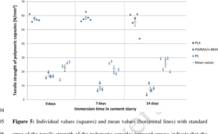
The tensile strength of PLA seems to be the highest according to Figure 5 but results 284
must be nuanced. 285
The measured tensile strength of PLA (around 60 N/mm2) meets the values reported in 286
literature [28]. For PS capsules, the tensile strength is underestimated as the PS tubes 287
broke inside the epoxy resin, which was situated between the capsule and the nut 288
represented Fig. 3, or the epoxy resin slipped. Tabulated values of PS tensile strength 289
are around 50 N/mm2 [42] i.e. twice as high as the measured values. For P(MMA/n-290
BMA), breakage occurred at the interface between the epoxy resin and the tube. So the 291
tensile strength should be higher than the obtained values. Therefore, P(MMA/n-BMA) 292
probably has the lowest tensile strength of around 10 to 20 N/mm2. 293
For all polymers, the measured tensile strength is higher than the tensile strength of 294
cementitious materials (5 N/mm2) and the one of PLA is close to the one reported by 295
Van Tittelboom for glass capsules (around 60 N/mm2) [13]. 296
Exposure of the capsules to an alkaline environment for 7 or 14 days does not result in 297
an significant difference in tensile strength for PLA and PS according to a one-way 298
ANOVA. However there is a significant difference (significance level of 0.01) for 299
P(MMA/n-BMA) as tensile strength of capsules placed in filtered cement slurry show a 300
lower tensile strength. 301
15 303
304
Figure 5: Individual values (squares) and mean values (horizontal lines) with standard 305
error of the tensile strength of the polymeric capsules (upward arrows indicate that the 306
values should be higher) versus immersion time in cement slurry. 307
308
The recorded elongation can also be analysed to compare the elongation at rupture as 309
illustrated in Figure 6. All the elongations at rupture were between 0.5 mm and 2 mm 310
which should represent 2.5 % to 10 % considering only that the 20 mm unfilled part of 311
the tube can deform (but these values have to be nuanced as some breakage did not 312
occur in the centre part and some samples have slipped in the epoxy resin). The smallest 313
elongations have been registered for P(MMA/n-BMA) (2 % - 4 %) while PS and PLA 314
seem to have almost the same behaviour (elongations between 4 % and 10 %). This 315
could indicate that P(MMA/n-BMA) is the most brittle material tested among the 3 316
polymers. Exposure to high pH during 7 days and 14 days does not influence the 317
brittleness of PS and P(MMA/n-BMA). For PLA, elongations are significantly lower 318
after 7 days in filtered cement slurry (significance level of 0.05). Considering the high 319
16
value of the standard error at 14 days, no conclusion can be drawn about the influence 320
of alkaline environment on elongation at breakage of PLA. 321
322
323
Figure 6: Individual values (squares) and mean values (horizontal lines) with standard 324
error of the elongation at rupture of the polymeric capsules versus immersion time in 325
cement slurry. 326
327
3.2 Bond strength tests 328
For several capsules (especially the ones with a small diameter and wall thickness 329
(PLA)), failure was caused by breakage of the capsules and slippage between the epoxy 330
(the resin holding the nut and screw thread linked to the test bench or the glue inside the 331
capsule) and the polymeric capsules (probably after breakage of polymeric capsules). 332
For these samples, the bond strength should be higher than the reported value. As 333
illustrated in Figure 7, the bond strength between PS capsules and mortar is the best one 334
with an average value around 3.5 N/mm2. This value is higher than the ones reported 335
[13] for glass (between 0.2 N/mm2 and 1 N/mm2) and ceramic (average value around 336
17
3 N/mm2). The bond strengths between PLA or P(MMA/n-BMA) and the cementitious 337
matrix are close to the one between glass and the cementitious matrix. 338
339
340
Figure 7: Individual values (squares) and mean values (horizontal lines) with standard 341
error of bond strength between polymeric capsules and cementitious matrix (upward 342
arrows indicate that values should be higher because failure was not caused by bond 343
loss). 344
345
3.3. Differential Scanning Calorimetry 346
From the DSC measurements, it results that the Tg of PLA and P(MMA/n-BMA) is
347
around 60 °C. Concerning P(MMA/n-BMA), this is more than the expected value of 348
50 °C announced by the supplier. For PS, the measured Tg is of around 102 °C. These
349
values are relatively high compared to the initial investigated range of glass transition 350
temperatures between 35 °C and 50 °C but are reasonable for PLA and P(MMA/n-BMA) 351
regarding their low cost. 352
18 354
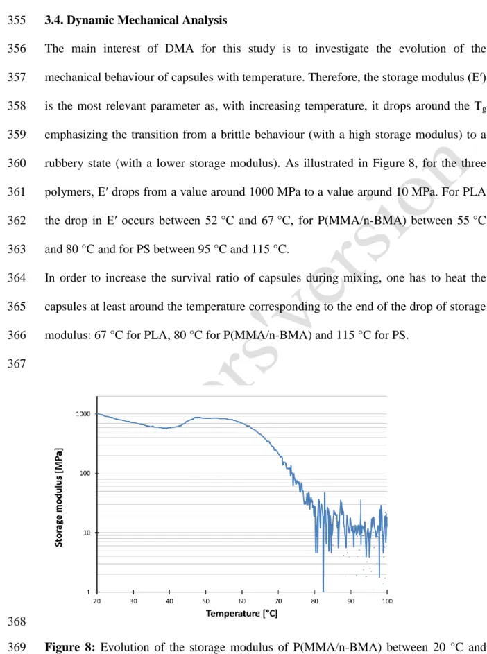
3.4. Dynamic Mechanical Analysis 355
The main interest of DMA for this study is to investigate the evolution of the 356
mechanical behaviour of capsules with temperature. Therefore, the storage modulus (E′) 357
is the most relevant parameter as, with increasing temperature, it drops around the Tg
358
emphasizing the transition from a brittle behaviour (with a high storage modulus) to a 359
rubbery state (with a lower storage modulus). As illustrated in Figure 8, for the three 360
polymers, E′ drops from a value around 1000 MPa to a value around 10 MPa. For PLA 361
the drop in E′ occurs between 52 °C and 67 °C, for P(MMA/n-BMA) between 55 °C 362
and 80 °C and for PS between 95 °C and 115 °C. 363
In order to increase the survival ratio of capsules during mixing, one has to heat the 364
capsules at least around the temperature corresponding to the end of the drop of storage 365
modulus: 67 °C for PLA, 80 °C for P(MMA/n-BMA) and 115 °C for PS. 366
367
368
Figure 8: Evolution of the storage modulus of P(MMA/n-BMA) between 20 °C and 369
100 °C. 370
19 371
3.5. Compatibility with healing agent 372
Pictures of the capsules, taken regularly during 14 days after injection of the healing 373
agent, revealed that the polyurethane pre-polymer hardens in the polymeric capsules. 374
However, the speed of hardening seems different for the 3 polymers. First hardening 375
signs have been observed after 5 days for P(MMA/n-BMA) capsules and after 4 days 376
for PLA capsules, while hardening started after 10 days in PS capsules (and no white 377
deposits were observed, only a global change in colour was noticeable). Even after 3 378
weeks PU was not completely hard in PS capsules when 2 capsules were cut. This 379
curing of the pre-polymer is probably due to a lack of permeability of the studied 380
polymeric capsules or a possible reaction between the pre-polymer and the capsule. All 381
these times of curing are still much too fast to be applicable in self-healing concrete and 382
the shelf-life of the capsules must be increased. 383
384
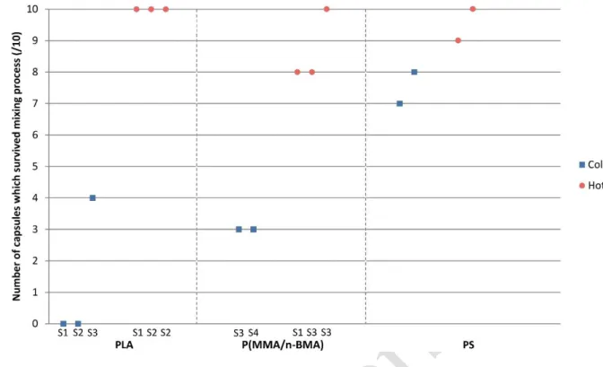
3.6. Mixing tests 385
At the end of the mixing test, entire capsules and parts of capsules were found in the 386
concrete mix. The survival ratios are reported in Figure 9. 387
20 389
Figure 9: Survival ratio of polymeric capsules during cold and hot concrete mixing 390
process. 391
392
The improvement in survival ratio after hot mixing is assumed to be caused by the more 393
flexible behaviour of the capsules above their Tg. For PLA, all the capsules survived the
394
hot mixing process, even the very small ones with a wall thickness around 0.4 - 0.5 mm 395
(S1 see Table 5) whereas none survived the cold mixing process. For P(MMA/n-BMA), 396
capsules had bigger dimensions so that could explain the slightly higher cold survival 397
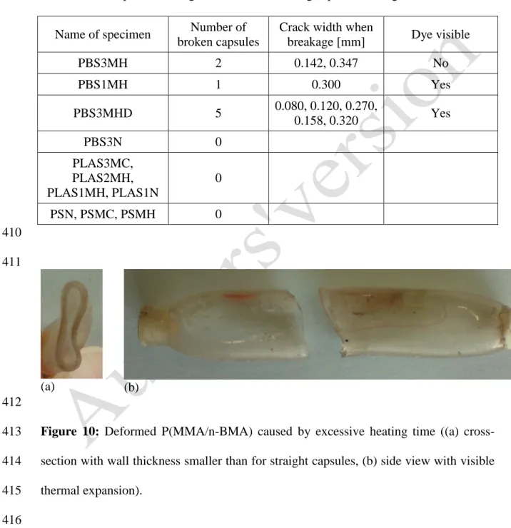
ratio. The capsules heated during 1 hour were flat and the wall thickness a little bit 398
smaller maybe due to thermal expansion before mixing (as illustrated in Figure 10, the 399
capsule is larger close to the sealing MMA glue) inducing a different resistance due to 400
their new shape whereas the capsules heated only 30 minutes conserved their cylindrical 401
shape and all survived the mixing test. PS capsules were initially the ones with the 402
biggest diameter and wall thickness. Therefore it is supposed that this is the reason why 403
they survived the cold mixing process rather well. The improvement between the cold 404
21
and hot mixing process for PS capsules is noticeable even if it is not sure the capsules 405
temperature remained above their Tg (102 °C) during all the mixing process as the final
406
temperature of the ‘hot concrete’ mix has been measured to be around 70 °C. 407
408
Table 5: Three-point-bending test results concerning capsule breakage. 409
Name of specimen Number of broken capsules
Crack width when
breakage [mm] Dye visible
PBS3MH 2 0.142, 0.347 No PBS1MH 1 0.300 Yes PBS3MHD 5 0.080, 0.120, 0.270, 0.158, 0.320 Yes PBS3N 0 PLAS3MC, PLAS2MH, PLAS1MH, PLAS1N 0 PSN, PSMC, PSMH 0 410 411 (a) (b) 412
Figure 10: Deformed P(MMA/n-BMA) caused by excessive heating time ((a) cross-413
section with wall thickness smaller than for straight capsules, (b) side view with visible 414
thermal expansion). 415
416
3.7. Three-point-bending tests with mortar specimens containing capsules 417
The results of the first test for all the capsules are presented in Table 5 with the codes 418
presented in Table 3. 419
22 420
3.7.1. Polystyrene and Poly(lactic acid) capsules 421
None of the PS and PLA capsules broke when cracks with a width of 0.4 mm were 422
created. No drops were observed on the load curves and no water marks were observed. 423
During the second test, the PS capsules broke without visible slippage when the 424
specimens were completely broken. The fact that PS capsules only broke when the two 425
parts of the specimen were disconnected can be explained by the wall thickness of the 426
capsules. Breakage of the capsules occurred suddenly. Consequently, the brittle 427
behaviour of PS capsules is confirmed. Also the good bond strength of PS capsules with 428
the cementitious matrix is verified as the capsules were not pulled out even if the load 429
was around 6 kN. 430
PLA capsules also broke during the second test, but most of them broke just before 431
specimen failure at loads of around 5.5 kN. A white colour caused by plastic 432
deformation of the capsules was observed. This explains why the capsules did not break 433
during the first test even though the wall thickness was small (around 0.4 mm for the 434
smallest ones). Moreover, some small capsules (PLAS1N and PLAS3MC) were pulled 435
out when the two parts of the specimens were disconnected. This indicates that there is 436
unsufficient bond between these PLA capsules and the cementitious matrix. 437
438
3.7.2. Poly(methyl methacrylate/n-butyl methacrylate) capsules 439
Some P(MMA/n-BMA) capsules broke with crack appearance. For the two specimens 440
with incorporated deformed capsules, which previously survived the hot mixing process, 441
some capsules broke and released the water they initially contained as illustrated in 442
Figure 11. For two other specimens with capsules which previously resisted the 443
concrete mixing process but were not deformed, breakage of capsules was observed. 444
23 445
446
Figure 11: Water released because of capsule breakage in the specimen PBS3MHD. 447
448
The crack width at which the capsules broke was deduced from the graphs representing 449
the load in function of the crack width measured by the LVDT. When a sudden drop in 450
the curve was observed (as illustrated in Figure 12) and the sound of capsule breakage 451
was heard, the capsules were supposed to be broken. 452
453
Almost all the capsules which were mixed in while heated and which deformed, broke 454
during the three-point-bending test (5/6): 3 capsules broke when the crack width was 455
around 0.15 mm, which corresponds to a relatively small crack. Therefore, if the healing 456
agent could be encapsulated by these capsules, healing of cracks with a width of around 457
0.15 mm could be possible. 2 other capsules broke while the crack width was around 458
0.30 mm. None of the P(MMA/n-BMA) capsules which had not been mixed previously, 459
broke during the three-point-bending test. 460
24 462 (a) 463 464 (b) 465
Figure 12: Loading curves obtained during the three-point-bending test, (a) without 466
capsules breakage, (b) with capsules breakage (specimen PBS3MHD2) 467
468
The second test confirmed that all the capsules were broken during the first test for one 469
of the two specimens (PBS3MHD) as the capsules were empty. For the other specimen 470
(PBS3MHD) containing deformed capsules, one capsule broke when the load was 471
around 4 kN releasing the water it was containing. For the straight P(MMA/n-BMA) 472
capsules which survived the hot mixing process, all the capsules which did not break 473
25
during the first test, broke during the second test before specimen failure at loads around 474
3.5 - 4.5 kN (pauses were made every 1 kN to check if water marks appeared). For the 475
P(MMA/n- BMA) capsules which had not been mixed with concrete, breakage occurred 476
at higher loads around 5 kN and even sometimes at the moment of complete specimen 477
failure. These results demonstrate that the chance of capsules breakage is higher when 478
the capsules have been previously mixed in (and probably damaged, as, in certain cases 479
visible precracking was noticed). 480
The results obtained during the three-point-bending test confirmed the first trends 481
observed with the tensile and bond strength tests: 482
- The P(MMA/n-BMA) capsules are the most brittle ones and they can break when they 483
are subjected to relatively small deformations as in the case when a crack appears, 484
- The bond of all the capsules with the cementitious matrix, except the smallest PLA 485
capsules, seems sufficient to avoid pull out of the capsules. Therefore, the majority of 486
the capsules broke during the three-point-bending test (at least during the second test). 487
The P(MMA/n-BMA) capsules are the only ones which broke at the moment of crack 488
appearance. This indicates that the brittleness of the polymeric capsules has to be as 489
high as possible. PS is known for its brittleness, but the capsules extruded in this study 490
were probably too thick to break. Therefore, besides the brittleness, the shape of the 491
capsules plays an important role. After complete breakage of the specimens, the 492
thickness of the broken P(MMA/n-BMA) capsules was measured. It revealed what was 493
expected after the mixing test: the wall thickness of the deformed capsules is lower than 494
the thickness of the straight capsules. This difference in thickness of the capsules which 495
survived the mixing process is probably the cause of the better breakage efficiency of 496
the deformed capsules. 497
26 499
4. Conclusions and perspectives 500
The use of polymeric capsules to obtain self-healing properties in concrete seems 501
promising. In this study, it was investigated whether brittle thermoplastics can resist the 502
concrete mixing process through heating, and break with crack appearance at room 503
temperature. The selected polymers P(MMA/n-BMA), PLA and PS show a brittle 504
behaviour at room temperature with an elongation at rupture lower than 10 %. Their 505
glass transition temperatures, measured by DSC is relatively low: respectively 59 °C, 506
59 °C and 102 °C. Tensile strength tests ensured that the tensile strength of these 507
polymeric capsules (10 to 80 N/mm2) is higher than the tensile strength of concrete 508
(5 N/mm2). Bond strength tests revealed that polymeric capsules can have similar bond 509
strength with concrete as glass capsules (around 1 N/mm2). Therefore, it is expected that 510
these capsules will not lower the mechanical properties of concrete when they are 511
embedded inside the matrix. The dynamic mechanical analysis showed a drop in the 512
storage modulus around the Tg of the 3 polymers. This drop emphasizes an important
513
loss of rigidity occurring along small temperature ranges: between 52 °C and 67 °C for 514
PLA, between 55 °C and 80 °C for P(MMA/n-BMA) and between 95 °C and 115 °C for 515
PS. Therefore, it is possible to adjust accurately the temperature at which capsules have 516
to be heated to obtain the desirable softness and increase the chance to survive the 517
concrete mixing process. The compatibility between polymeric capsules and the two-518
component polyurethane-based healing agent needs to be improved. The prepolymer of 519
this healing agent starts to harden in the capsules probably because of the air and 520
moisture permeability of the polymers. A combination of glass to protect moisture 521
sensitive healing agent, and thermoplastic to protect glass against mixing could be a 522
possible solution to this problem. The mixing of concrete with incorporated capsules 523
27
demonstrated the interest to heat the capsules beforehand. When capsules were mixed at 524
room temperature with aggregates, sand, cement and water, only the ones with an 525
important wall thickness (around 1.6 mm for PS capsules) resisted the process, 526
exhibiting a high survival ratio (over 8/10). The majority of the capsules with a wall 527
thickness between 0.4 mm (PLA S1) and 1.5 mm (P(MMA/n-BMA S3) did not resist 528
the mixing process at room temperature. However, when capsules were heated in a 529
small oven at temperatures above their Tg (90 °C for PLA and P(MMA/n-BMA),
530
140 °C for PS) and were mixed with heated aggregates and sand (80 °C for PLA and 531
P(MMA/n-BMA), 105 °C for PS) and boiling water, almost all the capsules resisted the 532
hot mixing process, even the smallest ones. Some P(MMA/n-BMA) capsules, which 533
previously survived the concrete mixing process, broke with crack appearance during 534
the three-point-bending test. The probability of breakage is linked to the wall thickness 535
of the capsules, their shape and, probably, the damage they suffered during the mixing 536
process because none of the P(MMA/n-BMA) which had not previously mixed in, 537
broke with crack appearance. 538
Although heating capsules prior to mixing seems complicated from an industrial point 539
of view, a deeper characterisation of the polymer degradation over time (increase of the 540
brittleness due to aging) supports the development of time-evolution capsules for 541
industrial applications in the future. The authors believe that polymeric capsules will be 542
useful to replace glass capsules to carry polymeric healing agent for self-healing 543
concrete because they can resist the concrete mixing process. Therefore, the global cost 544
of self-healing concrete will decrease, and the solution could be extended to industry in 545
large-scale concrete structural elements. 546
547
Acknowledgments 548
28
The authors would like to thank the Polymer Chemistry Research Group (Ghent 549
University) for its technical support to this study. 550
551
References 552
[1] E. Cailleux, V. Pollet, Investigations on the development of self-healing 553
properties in protective coatings for concrete and repair mortars, Proceedings of the 2nd 554
International Conference on Self Healing Materials, 2009. 555
[2] K. van Breugel, Is there a market for self-healing cement-based materials?, 556
Proceedings of the 1st International Conference on Self-Healing Materials, 2007. 557
[3] S. van der Zwaag, An Introduction to Material Design Principles: Damage 558
Prevention versus Damage Management, Springer, Dordrecht, 2007. p 1–18. 559
[4] K. Van Tittelboom, N. D. Belie, D. Van Loo, P. Jacobs, Self-healing efficiency 560
of cementitious materials containing tubular capsules filled with healing agent, Cement 561
and Concrete Composites 2011;33 (4):497 – 505. 562
[5] V. C. Li, Y. M. Lim, Y.-W. Chan, Feasibility study of a passive smart self-563
healing cementitious composite, Composites Part B: Engineering 1998;29 (6):819 – 827. 564
[6] C. Dry, Design of self-growing, self-sensing and self-repairing materials for 565
engineering applications, Proceedings of the society of photo-optical instrumentation 566
engineers, 2001, p. 23–29. 567
[7] C. Joseph, A. Jefferson, B. Isaacs, R. Lark, D. Gardner, Experimental 568
investigation of adhesive-based self-healing of cementitious materials, Magazine of 569
Concrete Research 2010;62:831–843. 570
[8] C. Dry, Matrix cracking repair and filling using active and passive modes for 571
smart timed release of chemicals from fibers into cement matrices, Smart Materials & 572
Structures 1994;3:118–123. 573
29
[9] C. Dry, W. McMillan, Three-part methylmethacrylate adhesive system as an 574
internal delivery system for smart responsive concrete, Smart Materials and Structures 575
1996;5 (3):297. 576
[10] C. Dry, M. Corsaw, A comparison of bending strength between adhesive and 577
steel reinforced concrete with steel only reinforced concrete, Cement and Concrete 578
Research 2003;33 (11):1723–1727. 579
[11] J. Wang, K. V. Tittelboom, N. D. Belie, W. Verstraete, Use of silica gel or 580
polyurethane immobilized bacteria for self-healing concrete, Construction and Building 581
Materials 2012;26 (1):532 – 540. 582
[12] P. Tran Diep, Quasi-brittle self-healing materials : numerical modeling and 583
applications in civil engineering, Ph.D. thesis, National University of Singapore, 2011. 584
[13] K. Van Tittelboom, Self-healing concrete through incorporation of encapsulated 585
bacteria- or polymer-based healing agents, Ph.D. thesis, Ghent University, 2012. 586
[14] C. Dry, Smart earthquake resistant materials (using time released adhesives for 587
damping, stiffening, and deflection control), Proceedings of the 3rd ICIM/ECSSM, 588
1996, p. 958–967. 589
[15] P. Tran Diep, J. Tay, S. Quek, S. Pang, Implementation of self healing in 590
concrete - proof of concept, The IES Journal Part A : Civil & structural Engineering 591
2009;2 (2):116–125. 592
[16] C. Dry, Smart multiphase composite materials that repair themselves by a 593
release of liquids that becomes solids.,SPIE Proceedings, Vol. 2189, 1994, p. 62–70. 594
[17] H. Liu, S. Quian, J. Van de Kuilen, W. Gard, M. de Rooij, E. Schlangen, 595
W. Ursem, Self healing of concrete cracks using hollow plant fibers, Proceedings of the 596
2nd International Conference on Self-healing Materials, 2009. 597
30
[18] C. Dry, Smart materials which sense, activate and repair damage; hollow porous 598
fibres in composites release chemicals from fibers for self-healing, damage prevention 599
and /or dynamic control, Proceedings of the 1st European Conference on Smart 600
Structures and Materials, 1992, p. 367–370. 601
[19] D. Janssen, Water encapsulation to initiate self-healing in cementitious materials, 602
Master’s thesis, Delt University of Technology, 2011. 603
[20] H. Mihashi, T. Nishiwaki, Y. Kaneko, N. Nishiyama, Development of smart 604
concretes, Proceedings of the 1st FIB Congress, 2002. 605
[21] M. M. Pelletier, R. Brown, A. Shukla, A. Bose, Self-healing concrete with a 606
microencapsulated healing agent, 2010. 607
[22] Z. Yang, J. Hollar, X. He, X. Shi, A self-healing cementitious composite using 608
oil core/silica gel shell microcapsules, Cement and Concrete Composites 609
2011;33 (4):506–512. 610
[23] I. Kaltzakorta, E. Erkizia, Silica microcapsules encapsulating epoxy compounds 611
for self-healing cementitious materials, Proceedings of the 3rd International Conference 612
on Self Healing Materials, 2011. 613
[24] X. Feng, N. Zhuo, H. Ningxu, D. Biqin, D. Xuexiao, H. Zhan, Z. Ming, 614
Selfhealing mechanism of a novel cementitious composite using microcapsules, in: 615
Proceedings of the International Conference on Durability of Concrete Structures, 2008. 616
[25] V. Wiktor, H. M. Jonkers, Quantification of crack-healing in novel bacteria-617
based self-healing concrete, Cement and Concrete Composites 2011;33 (7):763 – 770. 618
[26] K. Sisomphon, O. Copuroglu, Self healing mortars by using different 619
cementitious materials, Proceedings of the International Conference on advances in 620
construction materials through science and engineering, 2011. 621
31
[27] S. Mookhoek, Novel routes to liquid-based self-healing polymer systems, Ph.D. 622
thesis, Delft University of Technology, 2010. 623
[28] R. Auras, B. Harte, S. Selke, H. R., Mechanical, physical, and barrier properties 624
of poly(lactide) films, Journal of Plastic Film and Sheeting 2003;19:123–135. 625
[29] L. Baoa, J. Dorgan, D. Knauss, S. Hait, N. Oliveira, I. Maruccho, Gas 626
permeation properties of poly(lactic acid) revisited, Journal of Membrane Science 627
2006;285:166–172. 628
[30] H. Lehermeier, J. Dorgan, J. D. Way, Gas permeation properties of poly(lactic 629
acid), Journal of Membrane Science 2001;190:243–251. 630
[31] T. Komatsuka, A. Kusakabe, K. Nagai, Characterization and gas transport 631
properties of poly(lactic acid) blend membranes, Desalination 2008;234:212–220. 632
[32] L. Massey, Permeability Properties of Plastics and Elastomers, Second Edition: 633
A Guide to Packaging and Barrier Materials, Plastics Design Library, 2003. 634
[33] K. Babu, D. Babu, Behaviour of lightweight expanded polystyrene concrete 635
containing silica fume, Cement and Concrete Research 2003;33 (5):755–762. 636
[34] D. S. Babu, K. G. Babu, W. Tiong-Huan, Effect of polystyrene aggregate size on 637
strength and moisture migration characteristics of lightweight concrete, Cement and 638
Concrete Composites 2006;28 (6):520–527. 639
[35] B. Chen, J. Liu, Properties of lightweight expanded polystyrene concrete 640
reinforced with steel fiber, Cement and Concrete Research 2004;34 (7):1259–1263. 641
[36] B. Chen, J. Liu, L.-z. Chen, Experimental study of lightweight expanded 642
polystyrene aggregate concrete containing silica fume and polypropylene fibers, Journal 643
of Shanghai Jiaotong University (Science) 2010;15 (2):129–137. 644
[37] S. Melin, Why are crack paths in concrete and mortar different from those in 645
pmma?, Materials and Structures 1989;22 (1):23–27. 646
32
[38] A. Moroka, Basic properties of underwater polymer mortars using waste 647
expanded polystyrene-methyl methacrylate-based binders, in: RILEM International 648
Symposium on Environment-Conscious Materials and Systems for Sustainable 649
Development, 2004. 650
[39] E. Šušteršič, M. Tušar, Zupančič V.A., Rheological and mechanical 651
characterization of waste pmma/ath modified bitumen, Construction and Building 652
Materials 2013;38 (0):119 – 125. 653
[40] E. Šušteršič, M. Tušar, Zupančič V.A., Asphalt concrete modification with waste 654
pmma/ath, Materials and Structures 2013:1–8. 655
[41] A. Momayez, M. Ehsani, A. Ramezanianpour, H. Rajaie, Comparison of 656
methods for evaluating bond strength between concrete substrate and repair materials, 657
Cement and Concrete Research 2005;35 (4):748–757. 658
[42] D. Priddy, Kirk-Othmer Encyclopedia of Chemical Technology, Wiley, Ch. 659
Styrene Plastics, 2006. 660