UNIVERSITÉ DE MONTRÉAL
SURFACE FINISH CONTROL OF INCONEL 625 COMPONENTS PRODUCED BY ADDITIVE MANUFACTURING USING COMBINED CHEMICAL-ABRASIVE FLOW
POLISHING
NEDA MOHAMMADIAN
DÉPARTEMENT DE GÉNIE MÉCANIQUE ÉCOLE POLYTECHNIQUE DE MONTRÉAL
MÉMOIRE PRÉSENTÉ EN VUE DE L’OBTENTION DU DIPLÔME DE MAÎTRISE ÈS SCIENCES APPLIQUÉES
(GÉNIE MÉCANIQUE) SEPTEMBRE 2017
UNIVERSITÉ DE MONTRÉAL
ÉCOLE POLYTECHNIQUE DE MONTRÉAL
Ce mémoire intitulé:
SURFACE FINISH CONTROL OF INCONEL 625 COMPONENTS PRODUCED BY ADDITIVE MANUFACTURING USING COMBINED CHEMICAL-ABRASIVE FLOW
POLISHING
présenté par: MOHAMMADIAN Neda
en vue de l’obtention du diplôme de: Maîtrise ès sciences appliquées a été dûment accepté par le jury d’examen constitué de:
Mme BROCHU Myriam, Ph. D., présidente
M. TURENNE Sylvain, Ph. D., membre et directeur de recherche
M. BRAILOVSKI Vladimir, Ph. D., membre et codirecteur de recherche M. BALAZINSKI Marek, Docteur ès sciences, membre
DEDICATION
ACKNOWLEDGEMENTS
I would like to express my profound gratitude, and sincere gratitude to my advisor, Professor Sylvain Turenne, and my co-director, Professor Vladimir Brailovski for the excellent opportunity they have given me to study at Polytechnique Montréal and work at the “Laboratoire de recherche sur les Alliages à Mémoire et les Systèmes Intelligents (LAMSI) of École de Technologie Supérieure (ÉTS)”. Without their thrust, guidance, patience and continuous supports, my research would not have been successful. Undoubtedly, they were the most influential person during my M.Sc. and the best teachers of my student life. It was a great honor to work with you.
My immense appreciation extends to Professor Marek Balazinski and Professor Myriam Brochu serving as members of jury of my M.Sc. defense committee and for providing valuable comments.
I appreciate Consortium de Recherche et d’Innovation en Aérospatiale au Québec (CRIAQ) for their supports.
I would also like to thank ÉTS laboratory technicians for their excellent cooperation.
I am grateful to my colleagues at LAMSI laboratory, especially Alena Kreitcberg and Victor Urlea for all their helps.
My warmest thanks and appreciation to my parents for their unwavering supports, kind words and love. Also, my endless thanks to my brother for his support and kindness. Thank you for everything.
And finally, heartfelt thanks to my beloved husband, Esmaeil, who has been a constant source of support and encouragement during the challenges of graduate school and life. I am truly thankful for having you in my life.
RÉSUMÉ
Les secteurs manufacturiers à l’échelle mondiale, particulièrement dans les domaines de l’aérospatial et de l’automobile, expriment de plus en plus le besoin de produire des composants de géométrie complexe en utilisant des approches de fabrication additive plutôt que d’emprunter des voies de fabrication plus traditionnelles. Ainsi, les techniques de fabrication additive de fusion sélective par laser ou faisceau d’électron permettent de réduire le temps de fabrication et la quantité de matière pour produire les pièces tout en améliorant la performance des matériaux. Dans le procédé de fusion sélective par laser, un faisceau laser de haute puissance est utilisé pour fondre localement une poudre métallique pour fabriquer une pièce couche par couche. Cette méthode offre l’avantage de produire des composants à partir de matériaux durs et à haut point de fusion.
Bien que les techniques de fabrication additives permettent d’obtenir des caractéristiques uniques du point de vue de la géométrie des pièces, il demeure une problématique au niveau du fini de surface des composants, particulièrement pour les surfaces internes de pièces utilisées pour contenir des écoulements de fluide. La présence de particules partiellement fondues soudées à la surface peut causer une pollution indésirable dans le fluide de même que la rugosité de surface peut limiter l’écoulement du fluide. Ainsi, un des sujets les plus critiques en recherche qui amène une pénalité importante pour les procédés de fabrication additive concerne les opérations secondaires de finition de surface. Peu de résultats de recherche ont été publiés sur les procédés secondaires de polissage de surfaces internes dans les pièces de géométrie complexe. Ceci devient plus important considérant la variété de matériaux utilisés en fabrication additive. Les quelques résultats publiés reliés aux techniques de polissage chimique, électrolytique et mécanique montrent bien les limites de la fabrication additive.
Les principaux objectifs des travaux de recherche sont de concevoir, fabriquer et valider une méthode de polissage basée sur la combinaison de produits chimiques et de particules abrasives pour des surfaces internes de pièces aéronautiques en IN-625 produites par fabrication additive. Pour atteindre ce but, on envisage d’étudier : a) l’écoulement de produits chimiques, b) l’écoulement d’abrasifs et c) l’écoulement combiné de produits chimiques et d’abrasifs. Les effets de l’orientation de la surface par rapport à la direction de croissance de la pièce ainsi que celui de la vitesse du fluide de polissage seront considérés dans l’étude expérimentale de la
qualité du fini de surface découlant des trois techniques de polissage. Les résultats expérimentaux montrent la faisabilité d’adopter une approche combinée de polissage par écoulement de produits chimiques et d’abrasifs pour obtenir une meilleure efficacité de polissage. Par cette approche, les particules partiellement fondues en surface sont éliminées et la rugosité est sensiblement réduite.
ABSTRACT
World manufacturing sectors, in particular aerospace and automotive industries, wish to produce highly complex and customized components by adopting additive manufacturing (AM) of products compared to the conventional fabrication methods. This has brought attention to the AM techniques, most commonly selective laser melting (SLM) and electron beam melting (EBM), that have been proven to reduce time to market, decrease buy-to-fly ratio and improve parts performance. In the SLM process, a high-power density laser selectively melts and fuses powders within and between layers to produce a component. Several advantages are offered by SLM such as processing hard materials and production of materials with high melting points.
Regardless of excellent features of SLM additive manufacturing technique, the processing conditions lead to some surface problems in the case of internal surfaces of parts designed for fluid flows. This involves appearance of semi-welded particles attached to the surface, causing pollution in the fluid system, and relatively high surface roughness and texture, compromising the fluid flow. Therefore, one of the critical research issues and excessive cost factors penalizing AM approaches is post-processing surface finish. There is a lack of knowledge on the post-AM surface finish techniques that are appropriate for improving the internal surface quality of complex parts. This becomes more complicated when it comes to the wide range of materials produced by AM techniques. According to the review of the literature, some chemical, electrochemical and mechanical techniques have been investigated that deal with the polishing limitations of SLM-built parts.
The main objectives of this study were to design, manufacture and validate a post-SLM surface finish technique, used for internal surface polishing of tubular IN-625 parts designed for aerospace industry, employing a combination of chemical and abrasive flow actions. For this purpose, comprehensive experimental studies included: a) chemical flow polishing, b) abrasive flow polishing and c) chemical-abrasive flow polishing. The effect of SLM build orientation and fluid velocity on the surface finish quality for the three polishing techniques was studied. The obtained results showed the feasibility of using the combined chemical-abrasive polishing to reach better polishing efficiency. Indeed, the semi-welded powder particles attached to the surface were removed and surface roughness and texture notably improved.
TABLE OF CONTENTS
DEDICATION ... III ACKNOWLEDGEMENTS ... IV ABSTRACT ...VII TABLE OF CONTENTS ... VIII LIST OF TABLES ... XI LIST OF FIGURES ...XII LIST OF SYMBOLS AND ABBREVIATIONS... XVI
CHAPTER 1 INTRODUCTION ... 1
CHAPTER 2 LITERATURE REVIEW ... 5
2.1 Introduction ... 5
2.2 Chemical flow polishing ... 5
2.2.1 Chemical polishing process ... 5
2.2.2 Chemical reaction ... 7
2.2.3 Dynamic action in chemical polishing ... 8
2.2.4 Polishing solutions ... 10
2.3 Abrasive flow polishing ... 11
2.3.1 Mechanical polishing process using abrasive flow ... 11
2.3.2 Research on abrasive flow finishing techniques ... 11
2.3.3 Process parameters control for abrasive flow finishing performance ... 14
2.4 Chemical-abrasive flow polishing ... 17
CHAPTER 3 EXPERIMENTAL METHODS AND TECHNIQUES ... 24
3.1 Introduction ... 24
3.2.1 Pump and sensor ... 24
3.2.2 Wet materials ... 27
3.2.3 Safety plan ... 28
3.2.4 Cost ... 30
3.3 Experimental plan ... 31
3.3.1 Identifying experimental objectives ... 31
3.3.2 Optimizing the polishing fluid ... 31
3.3.3 Conducting the three polishing processes ... 33
3.3.4 Conducting the experimental study ... 35
CHAPTER 4 ARTICLE 1: SURFACE FINISH CONTROL OF ADDITIVLY-MANUFACTURED INCONEL 625 COMPONENTS USING COMBINED CHEMICAL-ABRASIVE FLOW POLISHING ... 38
4.1 Abstract ... 38
4.2 Introduction ... 39
4.3 Methodology ... 41
4.3.1 Experimental setup ... 41
4.3.2 Experimental conditions ... 42
4.3.3 Surface characterization before and after polishing ... 46
4.4 Results ... 48
4.4.1 Static versus flow chemical polishing ... 48
4.4.2 Comparison of chemical, abrasive and chemical-abrasive flow polishing processes 50 4.5 Discussion ... 56
4.5.1 Chemical flow polishing ... 56
4.5.2 Abrasive flow polishing ... 57
4.6 Conclusions ... 59
4.7 Acknowledgements ... 60
CHAPTER 5 GENERAL DISCUSSION ... 61
5.1 Introduction ... 61
5.2 Original scientific hypothesis ... 61
5.3 Discussion on some methodological aspects and results ... 63
5.4 Scaling up the chemical-abrasive polishing process ... 69
CHAPTER 6 CONCLUSION AND RECOMMENDATIONS ... 71
LIST OF TABLES
Table 3.1: Wet materials for the polishing setup parts resistant to high concentrated HF and HNO3 at room temperature ... 28
Table 3.2: Thesis project equipment and materials cost ... 30 Table 3.3: Results of roughness reduction for the abrasive flow polishing using three abrasive
particle sizes for the determined process conditions ... 32 Table 3.4: Experimental plan for the number of specimens used for each type of tests ... 34 Table 3.5: Experimental plan for investigating the correlation between various parameters
obtained by the studied polishing processes ... 36 Table 3.6: Specifications of Surface roughness tester SJ-410, Mitutoyo ... 36 Table 3.7: LEXT OLS4100 laser confocal microscope ... 37
LIST OF FIGURES
Figure 1.1: The process of selective laser melting (SLM) (Mumtaz & Hopkinson, 2010) ... 2 Figure 2.1: SEM micrographs a Ti-6Al-4V strut with an open porous structure (a) as-built, (b)
after chemical polishing, and (c) after the chemical-electrochemical polishing (Pyka et al., 2012) ... 6 Figure 2.2: The mass loss percentage of the specimens polished using ultrasonic cleaner and
magnetic stirrer (Łyczkowska et al., 2014) ... 10 Figure 2.3: Schematic illustration of the working principle of the abrasive flow machining
technique (Bremerstein et al., 2015) ... 12 Figure 2.4: Ra and Rz surface roughness, obtained by profilometry, of inner wall of the 500-µm
stainless steel 304 bores polished by abrasive flow polishing. (Yin et al., 2004) ... 14 Figure 2.5: Input parameters in AFM process (Bremerstein et al., 2015) ... 15 Figure 2.6: Surface roughness as a function of number of slurry passes for various abrasive
concentrations in abrasive flow polishing process of tool steel (JIS:SKD11) (Kurobe et al., 2002) ... 16 Figure 2-7: Surface roughness as a function of number of slurry pass for different abrasive
particle sizes in abrasive flow polishing process of tool steel (JIS:SKD11) (Kurobe et al., 2002) ... 16 Figure 2.8: Expected mechanisms for material removal of the CMP process (Lee et al., 2016) ... 19 Figure 2.9: Three trends of MRR in accordance with abrasive sizes in CMP process (Lee et al.,
2016) ... 20 Figure 2.10: Three trends of MRR in accordance with abrasive concentrations in CMP process
(Lee et al., 2016) ... 21 Figure 2.11: Schematic diagram of the slurry erosion wear test (Ramesh et al., 2014) ... 22 Figure 2.12: Influence of slurry concentration, speed and particle size on slurry erosive wear
Figure 3.1: Effect of various pumps on large particle concentrations in the slurry for CMP
process (Litchy & Schoeb, 2005) ... 26
Figure 3.2: Levitronix PTM, pump and mixer ... 26
Figure 3.3: Flow sensor design (LFS Levitronix) ... 27
Figure 3.4: Polishing setup dimensions... 29
Figure 3.5: (a) Safe installation of the pump and sensor devices far from the setup, and (b) air cooling module for the pump ... 30
Figure 3.6: Experimental plan flowchart ... 31
Figure 3.7: (a) Edge-shaped specimen with build orientations of 15º and 135º, and (b) plate-shaped specimen with build orientation of 135ᵒ on the rougher face... 34
Figure 3.8: (a) Polishing specimen assembly, (b) chemical abrasive fluid flow inside the polished specimen, (c) edge shape specimen on the SLM building platform ... 35
Figure 3.9: Surface roughness tester SJ-410, Mitutoyo ... 36
Figure 3.10: LEXT OLS4100 laser confocal microscope ... 37
Figure 4.1: (a) Schematic and (b) real illustration of the chemical abrasive polishing setup ... 42
Figure 4.2: (a) Polishing specimen assembly, (b) chemical abrasive fluid flow inside the polished specimen, (c) edge shape specimen on the SLM building platform ... 43
Figure 4.3: Surface roughness as a function of the surface orientation, as measured on as-built IN625 specimens (adapted from Urlea and Brailovski, 2017) ... 44
Figure 4.4: Roughness results of static chemical polishing for the four chemical solutions. The tests were performed for 8 hours at room temperature ... 45
Figure 4.5: Roughness measurement direction of the stylus profilometer for the edge-shaped specimen. Non-polished surface with build orientation of 15° ... 46
Figure 4.6: Planar view of the edge-shaped specimen captured by a confocal microscope for polishing depth measurements as a function of velocity... 47
Figure 4.7: Roughness improvement for static chemical polishing and chemical flow polishing processes at build orientations of 15° and 135°. Polishing time for the two processes was 1 hour ... 48 Figure 4.8: 3D topography confocal microscope surface images at two build orientations of 15°
and 135° for the as-built, static chemical polished and chemical flow polished surfaces. Polishing time for the two processes was 1 hour ... 49 Figure 4.9: Roughness improvement using the three polishing processes at build orientations of
15° and 135°. Polishing time for the three processes was 1 hour ... 50 Figure 4.10: Required polishing time for the 135° build orientation surface using different
polishing techniques to achieve similar surface roughness ... 51 Figure 4.11: Ra and Rz roughness versus polishing time through the three polishing techniques for
the two build orientations of (a, b) 15° and (c, d) 135° ... 52 Figure 4.12: 3D surface roughness profilometry for 15° build orientation before and after
polishing using three different polishing techniques for each increment of polishing time .. 53 Figure 4.13: 3D surface roughness profilometry for 135° build orientation before and after
polishing using three different polishing techniques for each polishing time increment ... 54 Figure 4.14: The logarithmic graphs show the polishing depth versus fluid velocity of the edge-shaped specimen using (a) chemical flow polishing, (b) abrasive flow polishing and (c) chemical-abrasive flow polishing (polishing time 1 hour, build orientation 135°). The scheme (d) represents the material removal pattern on the inclined surfaces of the edge-shaped specimen for the selected velocity range ... 55 Figure 4.15: Logarithmic graphs of (a) and (b) present the polishing depth versus the velocity for
build orientations of 15° and 135°, respectively. The results were obtained after applying chemical-abrasive flow polishing for 1, 2 and 3 hours ... 56 Figure 5.1: Striped texture exists on the as built surface and persists after chemical-abrasive flow
polishing for 1 hour on the build orientation of 15º, although the semi-welded particles are completely removed after chemical-abrasive flow polishing ... 64
Figure 5.2: Influence of particle impact angle on wear rate of non-heat treated St 37 (ductile material steel) (Kosa & Göksenli, 2015) ... 65
LIST OF SYMBOLS AND ABBREVIATIONS
A Cross sectional area through which the flow passes AFM Abrasive Flow Machining
Al2O3 Aluminium Oxide
AM Additive Manufacturing B Preston’s coefficient
c Concentration of the species in the bulk of the solution CAGR Compound Annual Growth Ratio
CeO2 Cerium(IV) Oxide
CFAAFM Centrifugal Force Assisted Abrasive Flow Machining
Cl2 Dichlorine
CMP Chemical Mechanical Polishing Cr2O3 Chromium (III) Oxide
D Diffusion coefficient of the reacting species in the solution
d Polishing depth
DBGAFF Drill Bit Guided Abrasive Flow Finishing dn/dt Dissolution rate
EBM Electron Beam Melting
ECA2FM Electrochemical Assisted Abrasive Flow Machining Fe2O3 Ferric Oxide
H2O2 Hydrogen Peroxide
H2SiF6 Hexafluorosilicic acid
HDPE High-Density Polyethylene
HNO2 Nitrous acid
HNO3 Nitric acid
IN-625 Nickel alloy (Inconel 625) IN-718 Nickel alloy (Inconel 718)
K Empirical constant in polishing depth equation LPBF Laser Powder-Bed Fusion
m Empirical constant in polishing depth equation M Surface atom in dissolution process
MAFM Magentic Abrasive Flow Machining MMR Material Removal Rate
n Empirical constant in polishing depth equation
NaCl Sodium Chloride
NoCl Nitrosyl Chloride
P Wafer Pressure
PFA Perfluoroalkoxy,
PTFE Polytetrafluoroethylene,
PTM Pump Tank Mixer
PVC Polyvinyl Chloride, PVDF Polyvinylidene Fluoride,
Q Flow rate
Ra Arithmetical average roughness value R-AFF Rotational Abrasive Flow Finishing Rz Average roughness depth
Si Silicon
Si3N4 SiliconNitride
SiC Silicon Carbide
SiO2 Silicon Dioxide
SKD11 Tool steel
SLM Selective Laser Melting ST-37 Steel
t Polishing time
Ti-6Al-4V Titanium alloy
Ti-6Al-7Nb Titanium alloy
v Flow velocity
V Relative velocity between the wafer and polishing pad
x Distance on the x-axis of edge-shaped specimen where the velocity is measured X Oxidizing agent in dissolution process
z Average particle size ZrO2 Zirconium Dioxide
δ Thickness of the reactant depleted layer neighboring the surface 𝜆c Distance the probe will travel for a single measurement
CHAPTER 1
INTRODUCTION
Inconel 625 is a nickel-based alloy containing mainly additive elements of carbon, chromium, molybdenium and niobium. This alloy possesses outstanding oxidation and corrosion resistance in industrial environment (Shankar et al., 2001). Excellent high temperature corrosion and stress resistance are the critical properties responsible for the reliability of this alloy in aircraft engine parts (Dinda et al., 2009).
Aerospace and automotive industries are increasingly interested in additive manufacturing (AM) of materials to fabricate fully functional parts from metal powders. This includes production of lightweight and highly complex nickel-based alloy parts. The process of AM refers to the fabrication of parts by depositing material layer by layer. There is a high geometric freedom in production of parts using a computer-aided design model (Petrovic et al., 2011). The commercial technological progress of AM for three decades comes into the higher accuracy, mechanical property improvements, increasing applications, and the cost reduction of facilities and AM-processed parts (Gibson, et al., 2015).
Mumtaz & Hopkinson (2010) described that laser powder-bed fusion (LPBF), known also selective laser melting (SLM), is a particular additive manufacturing technology, in which laser beam consolidate the metal to generate the parts. The use of this technology has the potential to reduce time to market, decrease buy-to-fly ratio and improve parts performance. Figure 1.1 shows the SLM process. The laser melts powdered metal, then, the powder bed moves downward after completing a layer. The next cross section of the part is built by adding a new layer of the metal powder by the powder depositor.
Figure 1.1: The process of selective laser melting (SLM) (Mumtaz & Hopkinson, 2010) SLM is a promising technique to be used for any purpose of production development such as design concept and low volume part production (Yadroitsev & Smurov, 2010). SLM-built Inconel 625 is a promising alloy that is used to fabricate high-performance components in aeronautics, chemical and petrochemical industries. Kreitcberg et al. (2017) showed that the overall mechanical strengths and elongation to failure of the SLM-built Inconel 625 equal or proceed to those of the annealed wrought alloy at room temperature. However, its elongation to failure at elevated temperature (760 ℃) is lower for the SLM-built specimens comparing to the annealed wrought ones. The mechanical properties of the Inconel 625 parts produced by SLM process can be improved by post-SLM HIP treatment. SLM process has a significant limitation due to relatively poor surface finish (Król & Tański, 2016). The surface roughness is critical for some parts functional properties like mechanical and frictional properties in order to avoid surface initiated cracking and thus premature failure (Pyka et al., 2013). Therefore, surface roughness reduction of SLM-built parts using post-processing techniques is a critical research
issue. Due to the complexity of the SLM-built parts and broad range of materials fabricated by this process, severe limitations exist for selecting the appropriate polishing technique. For example, chemical and electrochemical polishing techniques are limited by the chemical solutions and electrolyte, which are usually applicable for specific materials. For a new alloy, several tests are required to find the proper polishing medium. As for mechanical techniques, conventional mechanical polishing cannot be applied to finish the internal cavities of the complex parts.
Considering the challenges regarding the post-SLM surface finishing techniques, the research question of the current work is: could a combination of chemical and abrasive flow techniques advantageously be applied for efficient improvement of internal surface finish of AM IN-625 components?
The objective of this study is to show the feasibility and performance of the chemical-abrasive flow polishing process for surface finish control of the interior part of IN-625 SLM-built tubular samples. This investigation includes comparative studies on removal of semi-welded particles from the surface and surface roughness reduction using the three polishing techniques of chemical flow polishing, abrasive flow polishing and combined chemical-abrasive flow polishing.
Related to the scientific hypothesis of this work, it is needed to verify that there is a synergy effect in combining chemical and abrasive flow polishing techniques. The experimental procedure will be aimed to verify that the combined polishing technique lead to a more efficient removal of semi-welded particles from the surface and surface roughness reduction compared to the two other techniques applied separately.
To the knowledge of the master degree student, the chemical-mechanical polishing technique proposed in the present research work is the first of its kind based on pumping acidic chemicals as chemical polishing agent and abrasives as mechanical polishing agent through the interior surfaces of objects that could be viable for industrial practice.
The present thesis consists of six chapters, which starts with an introduction chapter, followed by the five other ones:
Chapter 2 presents a comprehensive literature review on three categories of surface finishing techniques: chemical flow polishing, abrasive flow polishing, and chemical-abrasive flow polishing. The existing research studies for the three polishing techniques and their limitations regarding the thesis objectives are addressed comparatively.
Chapter 3 presents the experimental methods and techniques. This chapter is devoted to the experimental setup including a brief overview of selection of setup parts, wet materials, safety plan and costs as well as the experimental plan for this study. The detail information on the experimental setup design, tests conditions and parameters used in the work are presented in chapter 4.
Chapter 4 presents the article entitled « Surface finish control of additively-manufactured Inconel 625 components using combined chemical-abrasive flow polishing » that was submitted in the Journal of materials processing technology. The comprehensive experimental studies on evaluating and comparing the surface finish quality of the tubular samples obtained by the three polishing techniques are explained. The synergy effect stemmed from combining chemical and abrasive flow actions are discussed through investigating the obtained results.
Chapter 5 presents the general discussion. This chapter provides insight into the studied problem of research and the presented solution by linking the objectives of the study, the results of the polishing tests, and comparative discussion on the obtained results.
CHAPTER 2
LITERATURE REVIEW
2.1 Introduction
This literature review aims at studying different post processing surface finish techniques applicable for components with complex internal structures, that are manufactured by powder-based additive technologies like Selective Laser Melting (SLM). These internal surfaces are difficult to access by many technological tools. With this objective in mind, three polishing technique have been studied, in which the flow of the polishing fluid through the interior surfaces of the parts are used: chemical flow polishing, abrasive flow polishing, and combination of chemical and abrasive flow polishing techniques.
2.2 Chemical flow polishing
2.2.1 Chemical polishing process
For removing semi-welded particles from the SLM built surfaces and obtaining desired surface roughness, chemical and electrochemical methods are commonly used.
The surface is chemically polished by immersion in an appropriate corrosive solution where the corrosion process is controlled. Chemical polishing is intended to remove materials from the metallic surface and reduce surface roughness with parallel dissolution of passivation layers. The passivation layer is created on the surface as an effect of polishing solution and galvanic couples. Surface finish quality relates to the ratio of the passive layer formation and dissolution of this upper layer rates. The chemical polishing is provided by a ratio equal to one. Metal oxidation happens at a ratio greater than one and metal etching occurs for the less than one ratios. (ASM-Vol.9, 2004)
It is possible to increase the polishing rate by combining chemical polishing with electrochemical polishing, or with applying dynamic action to chemical polishing process such as using ultrasound vibration, magnetic agitation or fluid flow. Pyka et al. (2012) showed that using a combination of chemical polishing and electrochemical polishing reduced the surface roughness of Ti-6Al-4V SLM-parts significantly. Firstly, semi-welded particles are removed by chemical polishing. Then, the surface roughness reduction is obtained by electrochemical polishing. Figure
2.1 shows the SEM micrographs of a typical strut, which is a visual confirmation for the effectiveness of the chemical-electrochemical treatment.
Figure 2.1: SEM micrographs a Ti-6Al-4V strut with an open porous structure (a) as-built, (b) after chemical polishing, and (c) after the chemical-electrochemical polishing (Pyka et al., 2012) This surface treatment allows achieving a homogeneous and controllable surface topography. However, electropolishing requires the use of conformal electrodes, which complicates the finishing of narrow channels and cavities (Urlea & Brailovski, 2017). Besides, it is difficult to electropolish multiphase alloys due to the different polishing rates of the phases. Surface finish quality depends on whether one phase is strongly cathodic or anodic comparing to the other phases. Preferential dissolution can occur for the matrix if the second or third phases are cathodic relatively, causing the others not to be attached. In addition, the interface between two phases can be dissolved preferentially (Donachie, 2000).
Eliminating the limitations of combined chemical and electrochemical technique, chemical polishing with a dynamic action allows finishing of inaccessible areas and multiphase alloys. It also increases the polishing rate by increasing material removal rate (ASM-Vol.9, 2004).
Different medium delivery techniques used for chemical polishing are comparatively discussed in Section 2.2.3.
2.2.2 Chemical reaction
Chemical polishing is utilized for surface treatment of metallic components fabricated by conventional or additive manufacturing (AM) techniques. In this process, the resulting passive layer of the polished metal has higher dissolving rate in the peaks compared to the pits because of water-deficiency of the diffusive layer in the pits (Łyczkowska et al., 2014).
Usually, when a surface is chemically polished, the initial surface reaction is oxidization -reduction process. In general, chemical polishing bathes contain two agents (Tuck, 1975):
An oxidizing agent: the oxidizing agent of the polishing solution, such as nitric acid or hydrogen peroxide, oxidizes the surface material. The oxidizer takes the place of the electric current applied in electropolishing process. Usually, the oxidization product is not soluble in the polishing solution and thus, remains on the surface.
A complexing agent: it reacts with the oxidized material to make a soluble complex, which can pass into the solution. For example, the most commonly used complexing agent in chemical polishing of titanium is hydrofluoric acid.
Furthermore, water is often used to dilute the chemical solution. A high proportion of chemicals are in the form of concentrated aqueous solutions.
The oxidization-reduction processes can be considered as a combination of cathodic and anodic reactions. In the first stage, the anode reaction takes place, where the surface of solid is dissolved in an oxidizing solution. The surface atom, M, becomes positive ion by losing an electron (the reaction simplified by assuming M to be singly charged).
M → M +
+ e - (2.1)
In the liquid, the oxidizing agent, X, diffuses to the surface and gains the electron, which is called the cathode reaction.
Anode and cathode areas can act alternatively. These areas are finely distributed over the solid surface. The overall reaction is obtained by combining Equation 2.1 and 2.2:
M + X ⇌ MX (2.3)
The atom, M, can be removed from the surface if the reaction product, MX, is soluble in the polishing solution. Otherwise, a complexing agent should be added into the chemical solution to form a soluble compound. For some materials having good corrosion resistance, the reaction product is dense and adherent to the metal, giving a protective layer against the corrosive solution. Taking the chemical polishing of silicon in a solution of nitric acid (oxidizing agent), hydrofluoric acid (complexing agent) and water (diluent) as an example, the overall dissolution process is obtained by adding cathodic and anodic equations:
Si + 2 HNO3 → SiO2 + 2 HNO2 (2.4)
Then, HF produces a soluble product by reacting with SiO2:
SiO2 + 6 HF → H2SiF6 + 2 H2O (2.5)
In some chemical polishing processes, the chemical reactions are more complicated. For instance, the solution constituents can react with each other. Goldstein (1960) studied this action for an aqua regia etchant used for chemical polishing of a semiconductor, where the reaction between the acids of HNO3 and HCl forms chlorine:
HNO3 + 3 HCl → NOCl + 2 H2O + Cl2 (2.6)
2.2.3 Dynamic action in chemical polishing
To understand the correlation between the dynamic action and the dissolution rate in chemical polishing, the dissolution process mechanism must be studied. Chemical reactions involved in chemical polishing (dissolution) process have been discussed in Section 2.2.2. (Tuck, 1975). The dissolution process mechanism could be described as a) reaction-controlled, b) autocatalytic, or c) diffusion-controlled. However, more than one dissolution processes can take place at the surface of material because sometimes several chemical reactions are involved in the process. Hence, the rate-limiting process for dissolution is the slowest mechanism.
Dokoumetzidis et al. (2008) explained that the dissolution in a reaction-controlled process is supposed to be a reaction on the polished surface, which takes place between undissolved species
and molecules of the dissolution medium. Therefore, the rate of dissolution is controlled by the reaction at solid-liquid interface. In other words, the concentration of the undissolved species controls the dissolution rate. Here, the solubility is referred to the concentration of the undissolved species after reaction equilibrium. Therefore, the dissolution rate is not affected by the dynamic action in a reaction-controlled process.
In a different manner, the dissolution rate of the autocatalytic reaction reduces by applying dynamic action as described by (Tuck, 1975). In the autocatalytic reaction, the concentration of the catalyst products controls the dissolution process, i.e. as the reactions at the solid-liquid interface proceed, they provide their own starting materials to continue the dissolution. Besides, an induction time is needed before getting to the steady-state rate of dissolution. Hence, introducing a dynamic action to the process may help removal of the catalyst products from the surface, and slow down the reaction.
When the rate-limiting process for dissolution is diffusion of reacting species to the surface, the concentration of the species close to the surface is assumed to be about zero because they are consumed continuously when reaching the surface. The thickness of reactant-depleted layer neighboring the surface reduces by applying dynamic action because the rate of approaching of the species to the surface is increases. As a result, the dissolution rate increases by introducing dynamic action to the chemical polishing for a diffusion-limited process (Tuck, 1975).
The effect of dynamic action on dissolution rate can be proved by studying the work done by (Łyczkowska et al., 2014). They investigated the effect of two different medium delivery methods, ultrasound vibration and magnetic agitation, on the mass loss of scaffolds made of Ti– 6Al–7Nb alloy by additive manufacturing. The loss of mass was a result of removing partially bound powder particles from surface and reducing the diameters of the parts. As shown in Figure 2.2, the percentage of mass loss was larger for the specimens polished using the ultrasound cleaner than those polished in the magnetic stirrer. Indeed, the dissolution rate increases by agitating the solution in a diffusion-controlled process, as a result of supplying fresh reactant to the surface, as described by (Vossen & Kern, 1978).
Figure 2.2: The mass loss percentage of the specimens polished using ultrasonic cleaner and magnetic stirrer (Łyczkowska et al., 2014)
2.2.4 Polishing solutions
A few systematic studies have been done in the literature giving detailed information on chemical polishing systems. This involves comprehensive investigations on chemical reactions occurring in the solution medium and on the surface of solid. There seems to be a lot of work for collecting all required data for a specific polishing system such as testing different compositions of the polishing solution, observing the effect of dynamic action, varying the temperature of the test and noting the effect of adding abrasives to the process. In addition, appropriate chemical bathes are often obtained during a trial. Thus, chemical polishing can be defined something of an art until more scientific information is collected in this area (Tuck, 1975).
The list of chemical polishing solutions for various materials are listed by ASM-Vol.9 (2004) and Kutzelnigg (1960).
Finally, an important factor for preparing an experimental plan for handling and management of chemicals in the tests is determining the associated hazards and risks. A book by National Research Council (US) (2011) delivers a practical guide for evaluating the risks and hazards with these chemical activities in the laboratory.
2.3 Abrasive flow polishing
2.3.1 Mechanical polishing process using abrasive flow
Mechanical polishing techniques use abrasives to reduce surface roughness of material by applying a controlled material removal on the surface. Mechanical polishing materials involve polishing wheels, abrasive stones, abrasive pastes, rubber polishers (Gonçalves et al., 2008) and abrasive fluids. Techniques using abrasive fluids for polishing material such as abrasive flow machining (AFM) (Rhoades, 1991), abrasive-waterjet machining (Relekar, Kalase, & Dubal) and abrasive flow polishing (Yin et al., 2004) are suitable for interior surface finishing of components. These processes are characterized by introducing a flow of abrasive fluid through the internal cavity of the work-piece, which are difficult to access by most of the finishing techniques. As an example, complex metal parts of additive manufacturing process show an inappropriate surface roughness for service requirements. AFM presents efficiency and accuracy for complex structure components.
The polishing mechanism of abrasive finishing processes is the interaction between abrasive particle and work-piece involving one or more of material deformation modes, such as cutting, ploughing and sliding. The cutting is referred to material removal process, ploughing is related to material displacement process and sliding is considered as a surface modification process (Yadav et al., 2011).
The force of abrasive particles, exerted by the fluid, produces abrasive action, which gently hones the raised surface features and edges. The abrasive finishing action can be compared to lapping or grinding operation as the abrasive medium smooths the internal surfaces of the work-piece (Yin et al., 2004).
The characteristics and applications of abrasive flow machining and abrasive flow polishing to finishing metal parts produced by additive manufacturing techniques are discussed in Section 2.3.2.
2.3.2 Research on abrasive flow finishing techniques
AFM is a new effective machining process that is used where interior surface finishing is required. The complex internal passages are difficult to reach by many conventional finishing techniques. AFM, as an advanced process, finishes the rough surfaces using a flow of very viscous, pressurized, semi-solid media through the work-piece. Polymeric carrier and abrasive particles such as Al2O3, SiC and diamond are the constituents of the abrasive medium (Gupta &
Chahal, 2015).
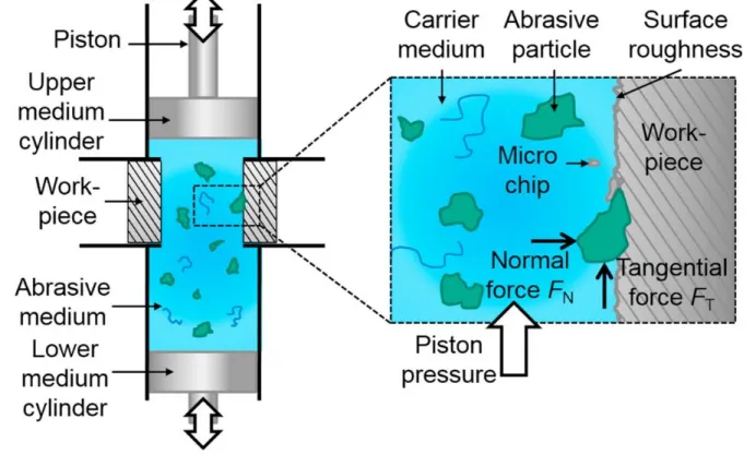
In AFM process, the work-piece is clamped and sealed between two opposing cylinders. The viscous abrasive medium is extruded back and forth into the work-piece by hydraulic pistons placed inside the cylinders (Bremerstein et al., 2015). Rhoades (1991) presented a detailed study on the process principles of AFM machining. Spur et al. (1997) also explained this advanced machining technique in general including the semisolid abrasive medium that is employed in the process. The concentration of abrasive particles in the polymeric carrier medium is up to 40 vol.%. The working principle of abrasive flow machining is shown in Figure 2.3.
Figure 2.3: Schematic illustration of the working principle of the abrasive flow machining technique (Bremerstein et al., 2015)
AFM has generally a low material removal rate, and it is labor intensive process. This limitation make the process complicated to be used for large stock-removal operations (Benedict, 1987). To improve the accuracy and efficiency of finishing operation of AFM, many modified processes such as Magnetic Abrasive Flow Machining (MAFM), Drill Bit Guided Abrasive Flow Finishing (DBGAFF), Centrifugal Force Assisted Abrasive Flow Machining (CFAAFM), Rotational Abrasive Flow Finishing (R-AFF), Spiral Polishing Method and Electrochemical Assisted Abrasive Flow Machining (ECA2FM) have been developed (Gupta & Chahal, 2015; Yadav et al.,
2011).
To overcome the restriction of low material removal rate, ECA2FM can be used, which offers a
better surface finish quality and higher material removal rate as compare to AFM process. ECA2FM is the hybrid process of electrochemical machining and abrasive flow machining
consisting of a salts-abrasive laden media passes into the cathode rod and the anode work-piece with the source of DC power. This process is a good example of a modified process combining electrochemical polishing and abrasive finishing technique, which results in more machining along with high surface finish quality in comparison to abrasive finishing technique taken individually (Gupta & Chahal, 2015).
AFM is capable of meeting the finishing requirements of different sectors of industrial applications such as aerospace, automotive, electronics, medical, precision dies and molds (Yadav et al., 2011).
High speed slurry flow finishing
Kurobe et al. (1998) developed the high-speed slurry flow finishing method that is used for high precision polishing of inner walls of stainless steel capillaries with fine holes and long size. The polishing action is performed by flowing of the high-speed slurry through the capillary. Yin et al. (2004) showed the feasibility of applying high-speed abrasive flow polishing for the surface roughness reduction of metal and ceramic micro-bores. The material removal mechanism is mainly abrasion. Abrasive polishing medium grinds the surface irregularities, leaving a uniform and smooth surface.
The inner wall polishing of inaccessible areas is very complicated to be performed by many ordinary polishing technologies. For instance, the electrolytic polishing and the honing have the limitation of means of polishing tools, while the magnetic polishing and chemical polishing need
to control the polishing media quality like magnetic fluid and chemical solution (Yasunaga, 1994). On the other hand, the high-speed slurry flow finishing employs the abrasive fluid as a polishing tool, where the fluid tool can conform to the shape of the work-piece hole (Kurobe et al., 2002). Yin et al. (2004) found that the surface roughness reduction increases with increasing the number of slurry passes and surface texture is eliminated within several polishing passes with abrasive flow polishing. The graphs of surface roughness measurements for the inner wall of the 500-µm stainless steel 304 bores obtained after abrasive flow polishing are shown in Figure 2.4.
Figure 2.4: Ra and Rz surface roughness, obtained by profilometry, of inner wall of the 500-µm stainless steel 304 bores polished by abrasive flow polishing. (Yin et al., 2004)
Despite many improvements in abrasive flow finishing techniques, there is space for more research in this area.
2.3.3 Process parameters control for abrasive flow finishing performance
Abrasive flow finishing process covers a huge range of finishing operations, where complexity of parts is a limitation for utilizing many ordinary finishing methods. Here, controlling the parameters of the process is very critical to achieve a uniform surface, predictable and repeatable results. For understanding the effect of process parameters on the surface finishing results, some related researches are reviewed in this section.
In AFM process, many input parameters can affect the surface finish quality and material removal rate. This makes it complicated to predict the process output parameters. Bremerstein et al. (2015) listed the input parameters of AFM into three groups of machines, work-pieces and work-piece fixtures, and abrasive medium, which are presented in Figure 2.5.
Figure 2.5: Input parameters in AFM process (Bremerstein et al., 2015)
Rajesha et al. (2010) stated that the rheological behavior of the abrasive medium dominates the results of AFM. Moreover, (Kar et al., 2009) stated that the percentage ingredients of the abrasive medium along with the number of cycles control the rheological behavior of the medium; hence, it is the basic input parameter. Considering the abrasive medium as the basic input parameter, Wang et al. (2007) conduct simulation and experiments to study the properties of abrasive gels in AFM. They found that a higher viscosity lead to more material removal rate due to the generation of larger shear force. Sankar et al. (2011) explained that more material removal rate is obtained by higher medium viscosity and larger particle size. However, this has a negative effect on the surface finish quality.
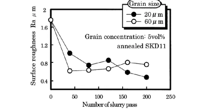
For abrasive flow polishing, Kurobe et al. (1998) showed that the abrasive concentration in the medium, particle size and slurry flow pass directly affect the surface finish quality of inner wall of a die hole (Figure 2.6 and 2.7). They reported that the surface roughness and polishing time decreases by increasing the number of slurry flow pass. Later, they showed that the hardness of die materials affects the surface roughness reduction. Therefore, the selection of polishing conditions like particle size and abrasive concentration is dependent on the polished material (Kurobe et al., 2002).
Figure 2.6: Surface roughness as a function of number of slurry passes for various abrasive concentrations in abrasive flow polishing process of tool steel (JIS:SKD11) (Kurobe et al., 2002)
Figure 2-7: Surface roughness as a function of number of slurry pass for different abrasive particle sizes in abrasive flow polishing process of tool steel (JIS:SKD11) (Kurobe et al., 2002)
2.4 Chemical-abrasive flow polishing
Combining the chemical flow polishing and abrasive flow finishing techniques might be an economic way of polishing surface integrities of AM components, which can be addressed in two concepts.
Firstly, there are some limitations for using chemical flow polishing and abrasive flow polishing individually:
Machining near net shape parts to the final dimensions is applicable for the parts with relatively simple geometry. This strategy was studied by Thakur & Gangopadhyay (2016) for nickel-based superalloys and Rawal et al. (2013) for AM spacecraft components of Ti-6Al-4V. For the parts with internal design complexities, techniques equipped with hard polishing tools are inadequate.
In abrasive flow machining, there is a limitation for polishing of large channels due to the high viscosity of the abrasive medium, (Rhoades, 1991).
As with chemical polishing, most of the solutions are applicable for specific alloys; no general chemical solution exists. For a new alloy, some tests should be performed to obtain the appropriate solution. For example, to the best knowledge of the authors’ knowledge, there is no proper chemical solution for Ni-Cr-Mo alloys. The high content of chromium and molybdenum in the composition of this family of alloys explain its exceptional chemical resistance to both oxidizing and reducing environments, (Crook, 2005).
Despite the efficiency of using electrochemical polishing for polishing AM components, the use of conformal electrodes complicates the polishing of narrow channels and cavities, (Urlea & Brailovski, 2017).
Secondly, using combined and modified techniques can overcome some of the limitations of chemical polishing and abrasive flow finishing methods, improving efficiency and accuracy of the finishing operation. ECA2FM process (explained in Section 2.3.2.) is an example of a
modified technique, which results in higher material removal rate and surface quality than the AFM process (Gupta & Chahal, 2015).
Using a combination of chemical and mechanical actions is an effective approach, however it is very complicated to understand and predict the results. The mechanisms of chemical reaction and mechanical material removal have been studied through two combined techniques of chemical mechanical polishing (CMP) and slurry erosion wear tests, which are presented in the following section.
Chemical Mechanical Polishing (CMP)
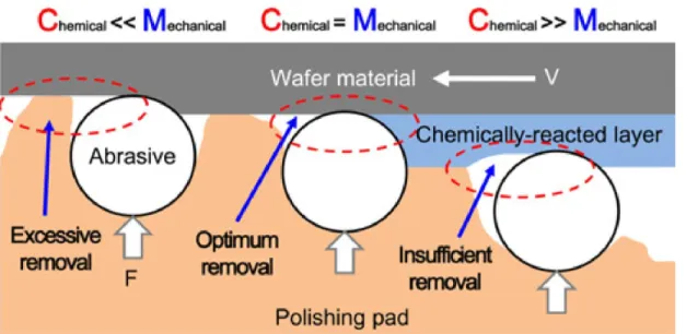
The CMP process is a combination of mechanical grinding and etching methods. In CMP, the surface is polished utilizing a chemical-abrasive slurry formulation and a mechanical action introduced by a downforce pressure of a pad simultaneously. Lee et al. (2016) reviewed the CMP process for surface polishing of Ti-6Al-4V alloy. They explained that investigating the chemical composition of the polishing slurry and the property of the target material is the key to clarify the chemical reaction mechanism of the CMP. Nevertheless, the basic factor for predicting the results of CMP is determining the mechanism of mechanical material removal. Different process parameters and consumables affect the complex mechanical action of the CMP. In respect to obtaining an optimum result for CMP, they stated that there must be a balance between the chemical reaction and the mechanical force. Insufficient removal occurs by excessive chemical action and an abundance of scratches arise on the surface after strong mechanical force. The expected mechanisms of material removal are presented in Figure 2.8.
To explain the role of chemical reaction in CMP, Si et al. (2011) described that the mechanical abrasion generated from sliding and rolling of the abrasive particles is easier on the oxidized or hydrated layer of the surface. The passive layer is produced continuously by a chemical reaction between the surface and the chemical slurry.
Figure 2.8: Expected mechanisms for material removal of the CMP process (Lee et al., 2016) The same as abrasive flow finishing, the process parameters and consumables like relative velocity, abrasive size, shape and concentration strongly influences the results of CMP process. Therefore, it is worth summarizing the mechanical characteristics of these process variables. According to the Preston’s equation (Preston, 1927), the basic model of wafer-scale material removal rate (MRR) is obtained as a function of wafer pressure (P) and relative velocity between the wafer and polishing pad (V):
MRR = B P V (2.7)
where the Preston’s coefficient (B) explains other process parameters of CMP.
As presented in Equation 2.7, the relative velocity affects MRR, its distribution and uniformity. The MRR increases with the velocity (Hocheng et al., 2000).
Lee et al. (2016) described some qualifications for the CMP abrasive particles:
There must be no agglomeration of abrasives in CMP slurry and the particles should be suspended.
The abrasives should not be dissolved in the chemical solution.
Their hardness must be greater than or equal to the surface material hardness.
The size, shape and concentration of the particles should be optimized to obtain controllable results. There is a complex relationship between these three factors.
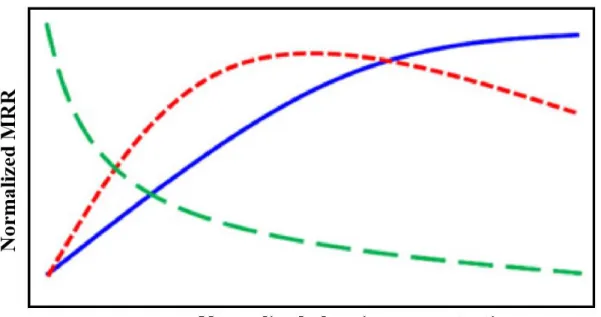
They explained that although a non-spherical shape of abrasive causes higher MRR, the use of spherical abrasive eliminated scratches on the surface. Three trends can be observed for the variation of MRR in a relation with the size and concentration of abrasives, which are shown in Figure 2.9 and 2.10. Lee et al. (2016) stated that obtaining conflicting trends for the MRR in the two presented figures is the result of complex relationship between abrasive size distribution, abrasive size and abrasive concentration. According to the model developed by Luo & Dornfeld (2003) for material removal mechanism in CMP process, two points should be considered in the influence of the abrasive size distribution on the material removal:
I. The size of the active abrasives: Larger abrasives result in higher MRR compared to the smaller ones, because of their larger indentation volume.
II. The number of active abrasives: The larger number of active abrasives increases the MRR. On the other hand, the real contact area between the material surface and polishing pad limits the number of active abrasives.
Figure 2.9: Three trends of MRR in accordance with abrasive sizes in CMP process (Lee et al., 2016)
Figure 2.10: Three trends of MRR in accordance with abrasive concentrations in CMP process (Lee et al., 2016)
Slurry erosion wear test
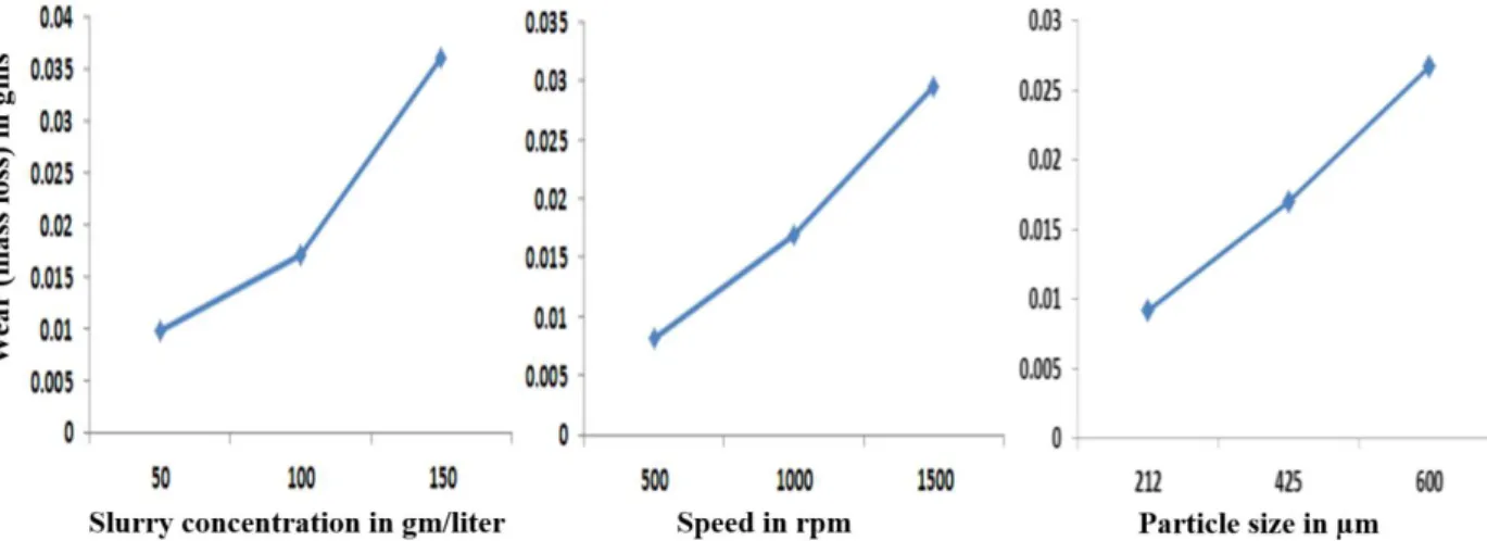
Slurry erosion wear test is a technique that is utilized to simulate slurry erosion wear in laboratory conditions. The test consists of a combination of chemical solution and abrasive particles jet-flow action. It is conducted to study the influence of different parameters such as flow speed, abrasive size and concentration of the slurry on erosion wear of the investigated surface material (Ramesh et al., 2011). Figure 2.11 illustrates an example of schematic representation of the slurry erosion wear tester, designed by Ramesh et al. (2014). They investigated slurry erosive wear behavior of inconel-718 coatings on copper. The specimen is fixed on the spindle, which is fully immersed in the slurry containing 3.5% NaCl solution and erodent silica sand particles. The size and concentration of abrasives, and the slurry rotational speed were the test variables. The slurry erosion wear was determined by calculating the weight loss of the coated specimen after the test. The wear results as a function of test variable are presented in Figure 2.12.
Figure 2.11: Schematic diagram of the slurry erosion wear test (Ramesh et al., 2014)
Figure 2.12: Influence of slurry concentration, speed and particle size on slurry erosive wear (Ramesh et al., 2014)
Research showed that the MRR increases by increasing the abrasive particle concentration (Ojala et al., 2015; Zuet al., 1990). Ramesh et al. (2014) described that more impingements are subjected to the surface by increasing the abrasive concentration in the slurry, which results in increment of mass loss. They also found that the MRR decreases with increasing the surface hardness, strength and corrosion resistance of the surface material. Lynn et al. (1991) studied the effect of particle size in slurry erosion rate of steel specimens in 1.2 wt.% SiC suspension in oil. They explained that decreasing the particle size leads to decrement of erosion rate because of the combined effect of two factors:
I. The proportion of abrasive particles impacting the surface decreases due to the decrement of collision efficiency of particles with decreasing particle size.
II. The impact velocity also decreases, which reflects decreasing of particle inertia for the smaller particles. Therefore, smaller particles are more easily deflected by the flow of the fluid near the surface to follow fluid streamlines, which decreases the impact angle of the particles to about 0º. In fact, by descending or ascending from intermediate impact angles, less material is removed from the ductile surface.
They also noted that for particle sizes greater than 100 μm, the erosion rate is in accordance with the kinetic energy of impacting particles for the dilute suspensions of the test. However, for smaller particles sizes, the dominant mechanism of material removal changes.
To conclude, in respect to the necessity of employing a mechanical force, CMP polishing is inappropriate for polishing complex components with inaccessible areas. Furthermore, studying erosion wear test is aimed for investigating the wear behavior of a material against chemical abrasive slurry, not for polishing the surface. However, studying the research in these areas helps to understand the mechanisms of material removal and the synergetic effect chemical and abrasive actions.
CHAPTER 3
EXPERIMENTAL METHODS AND TECHNIQUES
3.1 Introduction
The main purpose of this experimental study was to investigate the synergetic effect of chemical and abrasive flow polishing techniques with the aim of finishing the interior part of IN-625 surfaces fabricated by SLM process. For this purpose, three polishing techniques were investigated. Removal of semi-welded particles and surface roughness reduction were used to determine the performance of each polishing technique. The main parameters of the experiment were the surface roughness (Ra and Rz), the polishing depth, the surface texture and topography, fluid velocity, polishing time and build orientation. The methodology used to conduct for the current study is presented in Section 4.2. In this chapter, the complementary information regarding the experimental setup and the experimental plan is explained.
3.2 Experimental setup
A chemical-abrasive flow polishing setup in the laboratory was developed to apply a corrosive and erosive flow of acids and abrasive particles into the interior surface of hollow cylindrical specimen. The detailed information of the setup design and operation is presented in Section 4.3.1. The polishing fluid flow is generated and controlled by a centrifugal pump and the flow rate is measured by an ultrasonic flow sensor. In this section, the selection criteria and specifications of the pump and the sensor as well as the utilized wet materials of the setup are provided. Later, the safety procedure and cost of chemical tests and manufacturing the polishing setup are explained.
3.2.1 Pump and sensor
Improper handling methods of slurry and fluid delivery can cause damage in abrasive particles. The size distribution of the particles changes and agglomeration occurs in the system. This may significantly alter the slurry characteristics including viscosity, density and solid concentration (Johl et al., 2005). Nicholes et al. (2003) showed that agglomeration and production of large particles in CMP slurry results in surface defects such as micro-scratches.
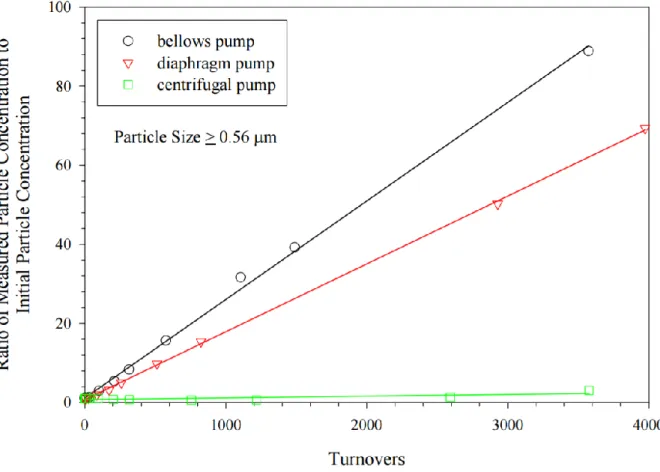
Studies have been done on the effect of slurry delivery technique on the metrology parameters of the slurry for CMP polishing systems (Johl et al., 2005; Litchy & Schoeb, 2005). Some of these studies have compared the performance of different pump and vacuum-pressure dispensing methods for slurry distribution in CMP process (Singh & Johl, 2001). The results of these investigations were helpful for the selection of the appropriate fluid delivery technology in our polishing setup. Litchy & Schoeb (2005) studied the effect of utilizing three pump types of bellows, diaphragm and centrifugal, on large particle concentration in the slurry without applying filtration to the system. They obtained significantly different results for the ratio of the measured concentration to the initial particle concentration as a function of turnovers for the three types of pumps. In the bellows and diaphragm pump systems, the large particle concentration for particles ≥ 0.56 µm increased by turnovers, due essentially to particle agglomeration. However, it remained constant for the centrifugal pump. They observed similar results of concentration changes for large particle sizes. Johl et al. (2005) reported no change for the large particle concentration until 100 turnovers and 40% decrement after 1000 turnovers using magnetically levitated (maglev) centrifugal pump. They explained that the advantage of maglev pumps in slurry handling is related to the use of a moderate shear level to the slurry, which results in crushing the loose agglomerates.
Based on the studied research, centrifugal pump was selected to be used for the chemical-abrasive polishing setup. The centrifugal pump tank mixer (PTM-1, Levitronix, max. flow rate of 17 L/min) was used for the polishing system. There is no mechanical wear in the mixing system of the pump, thus no particle coming from worn pump components occurs. The speed of the flow is electronically controlled by the pump impeller speed.
Figure 3.1: Effect of various pumps on large particle concentrations in the slurry for CMP process (Litchy & Schoeb, 2005)
An ultrasound sensor (LFS-20, Levitronix) was used to provide a flow range measurement of 0-20 L/min. The sensor avoids contamination due to its non-invasive measurement. Also, it has high accuracy and no particle generation because there is no moving part in the sensor. The flow control is in combination with the Levitronix PTM pump tank mixer.
Figure 3.3: Flow sensor design (LFS Levitronix) (www.levitronix.com)
3.2.2 Wet materials
Static chemical polishing tests was performed to select the proper chemical solution for the chemical-abrasive polishing process, which are presented in Section 4.3.2. The selected chemical solution was 40 vol.% of concentrated hydrofluoric acid (HF), 40 vol.% of concentrated nitric acid (HNO3) and 20 vol.% of distilled water. The criteria for selection of the wet materials of the
setup was good chemical resistance to the acidic-based chemical solution of the fluid in the room temperature. The list of used materials for different parts of the setup are presented in Table 3.1.
Table 3.1: Wet materials for the polishing setup parts resistant to high concentrated HF and HNO3 at room temperature (www.sevierlab.vet.cornell.edu, www.plasticsintl.com,
www.parrinst.com)
Setup part Wet material Supplier
Pump PFA / PTFE / Perfluoroelastomer / PVDF
www.levitronix.com
Sensor PFA
Tanks PVDF www.polyfab.com
Sealing O-rings Perfluoroelastomer www.gbs.ca
Tubing PVC
www.mcmaster.com
Pipe PVDF
Depletion tank HDPE
Valve PVC
Fittings PVDF / PVC
PFA: Perfluoroalkoxy, PTFE: Polytetrafluoroethylene, PVDF: Polyvinylidene fluoride, PVC: Polyvinyl chloride, HDPE: High-density polyethylene
3.2.3 Safety plan
It is necessary to create tailored safety plan for working with hazardous materials and processes in a laboratory. For this project, the safety operating procedure before conducting the experiments are listed below:
The training course, Atelier de formation en santé-sécurité, was taken to learn safety instructions of working in a laboratory.
For handling and management of chemical experiments, the risks of chemical activities were studied using the information provided in a book by National Research Council (US) (2011).
The chemical reactions of the acidic-based solution and abrasives were tested through static tests. Also, corrosion resistance of the wet materials of the setup was checked by immersing the parts in the selected chemical solution, 40 vol.% of concentrated hydrofluoric acid (HF), 40 vol.% of concentrated nitric acid (HNO3) and 20 vol.% of
distilled water, for 48 hours at room temperature.
Protective clothing including chemical resistant gloves (Barrier 2-100, www.ansellcanada.ca), chemical waste disposal containers (HDPE, www.mcmaster.com), lab coat (Polypropylene, SEC853, www.zenithsafety.com) and first aid box were prepared.
The size of the polishing setup parts for ordering were considered in a way that the set up can be easily mounted under the fume hood, model VBA-48, using a designed and built movable holder. The final set up dimensions was 80 × 30 × 80 cm3, which is shown in Figure 3.4.
The pump and sensor system devices including power supply and converters were installed out of the fume hood for safety purposes, as shown in Figure 3.5(a). To keep the devices cool, they were installed in vertical direction and a fan was used for cooling the pump converter. Also, an air cooling module is being used for cooling the pump motor, as shown in Figure 3.5(b).
Figure 3.5: (a) Safe installation of the pump and sensor devices far from the setup, and (b) air cooling module for the pump
3.2.4 Cost
The details of the equipment cost for the project of this thesis are presented in Table 3.2. Table 3.2: Thesis project equipment and materials cost
Equipment and material Cost ($)
S
etup
Pump & flow sensor 12 200 Polishing tanks 5 800 Miscellaneous parts 1 200 computer 1 000 Flu id Acids: HF + HNO3 700 Al2O3 abrasives 100
3.3 Experimental plan
The experimental strategy is the first stage of each experimental investigation, and it is necessary to define for any experimental study to conduct it properly. For this purpose, experimental plan, the process setup, materials and methods of analysis are studied thoroughly. The flowchart of experimental plan is presented in Figure 3.6 and explained in the following sections.
Figure 3.6: Experimental plan flowchart
3.3.1 Identifying experimental objectives
The first step of the experimental plan was defining the experimental objectives, scientific hypothesis and process parameters. The objectives and hypothesis of the studied work are presented in Chapter 1(Introduction). The process variables of the experiments are as follows: The input parameters are pump speed, temperature, flow pressure, flow rate, velocity of the fluid, fluid materials (chemicals and abrasive particles), composition and concentration of chemical solution, and abrasive size and concentration. Dependent characteristics are, polishing depth (µm) and surface roughness values for Ra and Rz (µm).
3.3.2 Optimizing the polishing fluid
The second step was optimizing the chemical and abrasive agents of the polishing fluid through preliminary static chemical polishing and abrasive flow polishing tests respectively.