HAL Id: hal-01007981
https://hal.archives-ouvertes.fr/hal-01007981
Submitted on 12 Oct 2016
HAL is a multi-disciplinary open access
archive for the deposit and dissemination of
sci-entific research documents, whether they are
pub-lished or not. The documents may come from
teaching and research institutions in France or
L’archive ouverte pluridisciplinaire HAL, est
destinée au dépôt et à la diffusion de documents
scientifiques de niveau recherche, publiés ou non,
émanant des établissements d’enseignement et de
recherche français ou étrangers, des laboratoires
Choice and limits of a fluid model for the numerical
study in dynamic fluid structure interaction problems
Jean-François Sigrist, Christian Lainé, Dominique Lemoine, Bernard Peseux
To cite this version:
Jean-François Sigrist, Christian Lainé, Dominique Lemoine, Bernard Peseux. Choice and limits of
a fluid model for the numerical study in dynamic fluid structure interaction problems. ASME 2003
Pressure Vessel and Piping Conference, 2003, Cleveland, United States. pp.87-93,
�10.1115/PVP2003-1820�. �hal-01007981�
CHOICE AND LIMITS OF A FLUID MODEL FOR THE NUMERICAL STUDY IN DYNAMIC FLUID STRUCTURE INTERACTION PROBLEMS
ABSTRACT
Jean Fran~ois SIGRIST Service Scientifique et Technique
DCN
Etablissement de Nantes lndret 44620 LA MONTAGNE, France [email protected]
Dominique LEMOINE Service Scientifique et Technique
DCN
Etablissement de Nantes lndret 44620 LA MONTAGNE, France [email protected]
This paper is related to the study of a nuclear propulsion reactor prototype for the French Navy. This prototype is built on ground and is to be dimensioned toward seismic loading. The dynamic analysis takes the coupled fluid structure analysis into account.
The basic fluid models used by design engineers are inviscid incompressible or compressible. The fluid can be described in a bi· dimensional by slice or a three-dimensional approach. A numerical study is carried out on a generic problem for the linear FSI dynamic problem. The results of this study are presented and discussed. As a conclusion, the three-dimensional inviscid incompressible fluid appears to be the best compromise between the description of physical phenomena and the cost of modeling.
The geometry of the reactor is such that large displacements of the structure in the fluid can occur. Therefore, the linearity hypothesis might not be longer valid. The case of large amplitude imposed oscillating motion of a cylinder in a confined fluid is numerically studied. A CFD code is used to investigate the fluid behavior solving the NAVIER-STOKES equations. The forces induced on the cylinder by the fluid are computed and compared to the linear solution. The limit of the linear model can then be exhibited.
1. INTRODUCTION
The mastery of design margins is both a technical and economical stake which is important for every industrial. Some of the possibilities to master and improve these desing margins is to
Christian LAINE
Service Scientifique et Technique DCN
Etablissement de Nantes lndret 44620 LA MONTAGNE, France christian.laine@dcn-nantes. com
Bernard PESEUX
Laboratoire de Mecanique et Mater!aux Division Mecanique des Structures Ecole Centrale de Nantes - 1, rue de La Noe
44321 Nantes Cedex 3, France bernard.peseux@ec-nantes. fr
increase the knowing of the numerical tool precision, to take into account physical phenomenons closer to the operating reality and to estimate errors due to the use of simplified models. A general R & D approach has been set up within DCN to match this need, and to elaborate simple criteria for pre-design and design analysis in order to master the design margins, with application to nuclear propulsion reactor.
The analysis of nuclear structures such as pressure vessel is a subject of numerous numerical studies [14], including dynamic analysis in general (11], and earthquake analysis in particular (13]. As the influence of the fluid on the dynamic behaviour of a structure could be possibly significant [9, 15], the whole numerical study on the industrial structure has to be performed by taking the fluid into account
The dynamic behaviour of structures coupled with fluid was the object of numerous studies, which use finite element or boundary element discretization [12], as well as ALE techniques [17] and CFD and FE coupling [1]. Howerver, the standard usage in the industrial fields of the methods developped in university researches is rare enough so that industrial such as DCN have interest in it Furthermore, the study of a coupled fluid/structure problem requires much more modelling time than the study of a single structure. As a consequence, it is useful! from an industrial point of view to use a simplified approach of the coupled problem and perform mechanical analysis using a coupled model only when necessary. When simplified fluid models are used, an estimation of
the deviation to the coupled model should be given in order to ensure the validity of the calculation toward the industrial design problem.
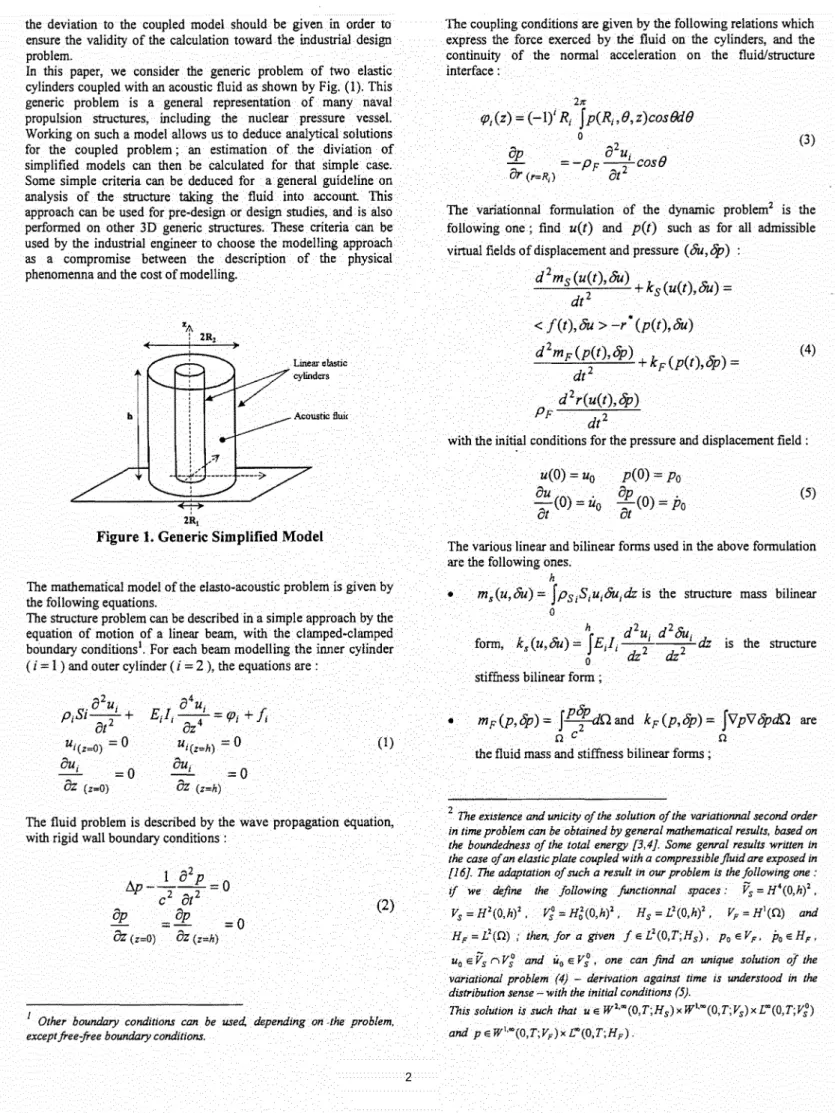
In this paper, we consider the generic problem of two elastic cylinders coupled with an acoustic fluid as shown by Fig. (1). This generic problem is a general representation of many naval propulsion structures, including the nuclear pressure vessel. Working on such a model allows us to deduce analytical solutions for the coupled problem ; an estimation of the diviation of simplified models can then be calculated for that simple case. Some simple criteria can be deduced for a general guideline on analysis of the structure taking the fluid into account. This approach can be used for pre-design or design studies, and is also performed on other 3D generic structures. These criteria can be used by the industrial engineer to choose the modelling approach as a compromise between the description of the physical phenomenna and the cost of modelling.
2R1
Figure 1. Generic Simplified Model
The mathematical model of the elasto-acoustic problem is given by the following equations.
The structure problem can be described in a simple approach by the equation of motion of a linear beam, with the clamped-clamped boundary conditions1• For each beam modelling the inner cylinder
( i
=
1 ) and outer cylinder (i
= 2 ), the equations are :flu
EJ;
--4-~=
fP;+
J:
oz
ui(z=h)=
0
OU;=0
OZ (z,h) (1)The fluid problem is described by the wave propagation equation, with rigid wall boundary conditions :
(2)
The coupling conditions are given by the following relations which express the force exerced by the fluid on the cylinders, and the continuity of the normal acceleration on the fluid/structure interface: 21t'
rp;(z)
=
(-Ii
R
1fp(R
1,8,z)cosBd8
0on
0
2U1• _r_ = -pF--cos8
&r
(r=R,) ot2 (3)The variationnal formulation of the dynamic problem2 is the following one ; find u(t) and p(t) such as for all admissible virtual fields of displacement and pressure (au,~) :
d
2m8(u(t),8u)k ( ()
~·)
_
2+
s
ut
,uu-dt
<
f(t),8u > -r • (p(t),8u)d
2mF(p(t),op)k ( () s:.) _
(4) 2+
F pt
,vp-dt
d
2r(u(t),~)
PF
dt2
with the initi_al conditions for the pressure and displacement field :
u(O)
=
u0 ou (0)=
uo
at
p(O)=Po
op(0)=
Po
at
(5)The various linear and bilinear forms used in the above formulation are the following ones.
h
• m3(u,8u) = fp81
S
1u18u1dz is the structure mass bilinear0
h dzu dz()u.
form,
k
5(u,8u) =JEJ
1- -2-1 -2 -1 dz is the structure 0dz
dz
stiffness bilinear form ;
•
mF(p,op)= fPTdnand kF(p,op)= fvpVopdn arenc
n
the fluid mass and stiffness bilinear forms ;
2 The existence and unicity of the solution of the variationnal second order
in time problem can be obtained by general mathematical results, based on the boundedness of the total energy [3,4]. Some genral results written in the case of an elastic plate coupled with a compressible fluid are exposed in [16]. The adaptation of such a result in our problem is the following one ·
if
we define the following junctionnal spaces: V5 = H4
(0,h)2,
V5
=
H 2(0,hi, V~
=
Hg(O,hl. Hs=
L2(0,h)2, Vp ""H\0) and HF = L2(Q) ; then, for a given f e L2(0,T;H3 ), Poe VF. Poe HF,h 2tr
•
r(p,u)
=
J
J[(-li
R;p(Ri,B,z)cosBdB]u(z)dz
is the 0 0fluid/structure interaction operator, r • (.,.) is the adjoint operator;
h
•
<
f,liu
>=Jfliudz
is the external force work linear form. 02. AN ENGINEER'S APPROACH : USE OF SIMPLIFIED FLUID MODELS
The elasto-acoustic coupled problem decsribed by Eqs. (1-5) can be simplified in an engineer's approach by the use of simplified fluid models.
• Model #1 :mass conservation model. In this model, the fluid is taken into account to satisfy the total mass balance of the structure with the fluid. This model is often used in pre-design when no information on the industrial complete problem are available. Applying such an approach to the generic problem is equivalent to calculate the fluid forces according to the following expressions :
•
•
(6)
Model #2 : fluid displaced mass model. In this model, the fluid forces are described in term of fluid displaced mass as in ARCHIMEDE's theorem. This model can be used for large fluid domains surrounding the structure. In our case, the fluid forces are given by :
(7)
Model #3: 2D hydrodynamic added mass model. In this model, the fluid problem is solve with the 2D LAPLACE equation, i.e. in each slice of fluid, neglecting 3D effects. The dynamic behaviour of the fluid is taken into account, and leads to the calculation of hydrodynamic added masses [8]. In the case of the generic problem studied here, the fluid forces are given by :
(8)
These models avoid to mesh the fluid domain, and because the resulting structure problem remains symmetric, spectral methods are applicable to study the dynamic problem. However, mechanical analysists in design office miss some general rules to choose between these models and other simple (3D compressible or 3D uncompressible) or more complex models to study industrial structures. Simple rules can be given in our generic problem, as shown bellow.
The air/water eigenfrequency ratio is given by :
/3=
1~l+KXA(a)
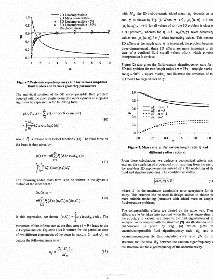
(9)where K is a constant depending on the geometrical and physical properties of the structure. ).(a)= a2 -1 for the mass conservation model, ).(a)=
1
for the displaced mass model andA.( a)= a
2
+
1 for the 2D incompressible model. Figure (2) plots-1
f3
versusa
for the various simplified models. Except fora
around the critical ratioa
0=
.J3,
the mass conservation model leads to an over-estimatedf3
ratio for small values ofa ,
and an under-estimatedf3
ratio for large values ofa .
This clearly shows that, even for pre-design sudies, the model actually used by the industrial is, for most cases, not valid and can lead to great errors. The ARCHIMEDE's model is physically valid for large fluid domain, but such a situation does not occur in the industrial problem. On the other hand, the 2D uncompressible model allows a physically correct approximation for the fluid problem, without meshing the fluid domain.However, the hydrodynamic mass approach might not be valid for geometries where 3D effects are to be taken into account. These effects are influenced by the structure shape, i.e. by the radius ratio
R
R
a
= - 2 and the length ratio 17= -
1 of the axi-symmetricR
1h
structure. In order to bound the validity domain of the 2D approximation, we perform a simple comparison of the 2D and 3D
approach, for our generic case, for which analytical solution can be expressed.
1.0 0.8 0.6 0.4 0.2 - - 2D Uncompressible - 2D Mass conservation A 3D Uncompressible • 5% c 3D Uncompressible- 50% .... · .. Displaced mass 0.0 + - - . , - - - - , . - - . , - - - . - - - , - - - . , . - - - - , . - - , - - , 2 3 4
5
6 7 8 9 10a
Figure 2.Water/air eigenfrequency ratio for various simplified fluid models and various geometry parameters
The analytical solution of the 3D uncompressible fluid problem coupled with the inner elastic beam (the outer cylinder is supposed rigid) can be expressed in the following form :
,
p(r,B,z,t) = "£.f't(r)xcos(}xcos(q1z) 1=0 h8
2 x J--T<s,t)cos(qzs)dsoat
(10)where
l'z
is defined with Bessel functions [18]. The fluid force on the beam is then given by :"'
tp(z)=
-trR"£.f't(R)x cos(q1z)x 1=0 h a2uJ-
2 (s,t)cos(qzs)dsoat
(II)The following added mass term is to be written in the dynamic motion of the inner beam :
""
1rR"£.f't(R)x(u,C1 )x(au,C1)
(12)
1=0
h
In this expression, we denote (u, C1) = ju(z )cos(q1 z )dz . The 0
truncation of the infinite sum at the first term (I
=
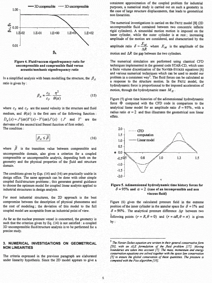
0) leads to the 2D approximation. Equation (12) is written for the particular case of two different eigenmodes ofthe beam in vaccum U; and U1 to deduce the following mass ratio :(13)
with
M
H the 2D hydrodynamic added mass. J.liJ depends ona
and11
as shown by Fig. (). When11
~ 0,J.Lu(a,11)
~ 1 andJ.lij
(a, 11);"'
1 ~ 0 for all values ofa
(the 3D problem is close toa 2D problem), whereas for
11
~ 1,J.Lu (a, 11)
takes decreasing values and J.lij (a,11 ),
i
::t. j takes increasing values. This denotes 3D effects as the length ratio11
is increased, the problem becomes three-dimensionnal; these 3D effects are more important in the case of a confined fluid (small values of a), which physical interpretation is obvious.Figure (2) also gives the fluid/vacuum eigenfrequency ratio for a 3D full problem for two length ratios (
11
= 5% triangle marks -and11
=50% - square marks), and illustrate the deviation of the 2D model for large values of11 •
1.0 0.8 0.6 ::L 0.4 -J.tll; a= 1.1 --J.tll;a=5
• • • ,at ;
a= 1.1• • - JJ21 ; o:=5
0.2 0.0 0.0 0.2 0.4 0.6 0.8 1.0 TJFigure 3. Mass ratio
J.L
for various length ratio11
and different radius ratiosa
From these calculations, we deduce a geometrical criteria wich express the condition of a bounded error resulting from the use of the meshless 2D approximation instead of a 3D modelling of the fluid and structure problems. The condition is written :
(14)
where
if
is the maximum admissible error acceptable for the study. This criterion can be used in design studies to choose the most suitable modelling (structure with added mass or coupled fluid/structure problem).The compressibility effects are treated by the same way. These effects are to be taken into account when the first eigenvalues of the structure in vacuum are close to the fisrt eigenvalues of the acoustic cavity coupled with the structure [9]. An illustration of the phenomenon is given by Fig. (4) which plots the vacuum/compressible fluid eigenfrequency ratio
Pc
and the vacuumluncompressible fluid eigenfrequency ratioP
1 for the structure and the ratiop
A between the vacuum eigenfrequency of the structure and the eigenfrequency of the acoustic cavity.1.00
Figure 4. Fluid/vaccum eigenfrequency ratio for uncompressible and compressible fluid versus
acousticfmecbanic eigenfrequency ratio
In a simplified analysis with beam modelling the structure, the
j3
A ratio is given by :(15)
where Cs and Cp are the sound velocity in the structure and fluid medium, and B(a) is the first zero of the following function:
Da(x)=J'(ax)Y'(x)-Y'(ax)J'(x) (J'
andY'
are the derivates of the second kind Bessel function of first order). The condition :(16)
where
j3
is the transition value between compressible and uncompressib!e domain, also gives a criterion for a coupled compressible or uncompressible analysis, depending both on the geometry and the physical properties of the puid and structure domain.The conditions given by Eqs. (14) and (16) are practically usable in design office. The same approach can be done with other simple coupled fluid/structure problems; this generates general guidance to choose the optimum model for coupled linear analysis applied to industrial strcuctures in design analysis.
For most industrial structures, the 2D approach is the best compromise between the description of physical phenomena and the cost of modeling ; the deviation of this model to the full coupled model are acceptable from an industrial point of view.
As far as the nuclear pressure vessel is concerned, the geometry is such that the criterion given by Eq. (14) is not satisfied: a coupled 3D uncompressible fluid/structure analysis is to be performed for a precise study.
3. NUMERICAL INVESTIGATIONS ON GEOMETRICAL NON LINEARITIES
The criteria expressed in the previous paragraph are elaborated under linearity hypothesis. Since the 2D model appears to give a
consistent approximation of the coupled problem for industrial purposes, a numerical study is carried out on such a geometry in the case of large structure displacements, that leads to geometrical non linearities.
The numerical investigations is carried on the FRITZ model [8] (2D uncompressible fluid contained between two concentric infinite rigid cylinders). A sinusoidal motion motion is imposed on the inner cylinder, while the outer cylinder is at rest ; increasing amplitude of the motion are considered, and characterised by the
amplitude ratio
o
=X
M whereX
M is the amplitude of the Mmotion and AR the gap between the two cylinders.
The numerical simulation are performed using classical CFD techniques implemented in the general code STAR-CD, which uses a finite volume discretization of the NA VIER-STOKES equations [6]
and various numerical techniques which can be used to model our problem in a consistent way3. The fluid forces can be calculated as a response to the structure motion. In the FRITZ model, the hydrodynamic force is proportionnal to the imposed acceleration of motion, through the hydrodynamic mass M H •
Figure (5) gives time histories of the adimensionnal hydrodynamic force
<I>
computed with the CFD code in comparison to the analytical linear model for an amplitude ratioo
=
95%, with a radius ratioa
= 2 and thus .msutrates the geometrical non linear effets. 2.0 1.5 1.0 0.5e
0.0 -0.5 -1.0 -1.5 -2.0 .... .,CFD computation --Linear model ' \ I • I"'-··
-··
.
'.
\'
\ 1.3.,,
..
1.5Figure 5. Adimensionnal hydrodynamic time history forces for
o
=
95% anda
=
2
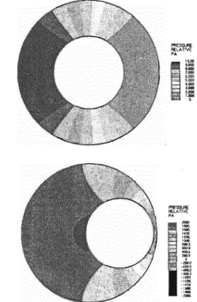
(case of an incompressible and non viscous fluid)Figure (6) gives the calculated pressure field in the extreme position of the inner cylinder in the annular space for
o
=
1% ando
=
90% . The analytical pressure difference D.p between two.
following points (r
=
R, ()
=
0)
and (r=
aR, ()
=
1l)
is given by:3
The Navier-Stokes equation are written in their general conservative form [20], with an ALE formulation of the fluid problem [17]. Moving boundaries are taken into account [7]. The mass, momentum and energy conservation equations are solved together with the space law conservation [5] to ensure the global consevation of these quantities. The pressure is computed with the Piso algorithm [ 10].
(17)
In our case, the analytical values are 11.84 Pa for
8
= 1% and1065.92 Pa for
8
= 90%. As shown by Fig. (6), the computed values is almost doubled for the case8
= 90%, and in good agreement with the analytical model for the case8
= 1% . The geometrical non linearities tend to raise the pressure difference between the two opposite sides of the innner cylinder along the axis (} = 0 , which can account for the raise of the computed pressure force exerced on the inner cylinder, Fig (5).Figure 6. Calculated pressure field in the extreme position of the inner cylinder for
8
= 1% and8 =
90%Another calculation calculation is performed on the same geometry with an incompressible and viscous fluid. Figure (7) compares the computed total fluid force (including pressure and viscous force) and the analytical linear approach of the problem, solved by CHEN [2].
In this case, the fluid forces are expressed in term of added mass and added damping, i.e. one can write :
(18)
with PFAh the added mass and PF[h the added damping.
viscous and turbulent fluid, in their study of the dynamic analysis of fuel storage racks subjected to seismic loads [19].
2 -Linear model
- CFD computation
•
o+---~--~r~r---,---,~~__,05 1.1
Figure 7. Adimensionnal time history total fluid forces for
8
= 75% and a= 2 (case of an incompressible and viscous fluid)A complementary numerical study is performed to show the convergence of the calculations as the mesh is refined, for the case of large motion of the inner cylinder, Fig. (8). The number of correction stages of the Piso algorithm does not increased as the inner cylinder is close to the outer cylinder. These two elements give good confidence in our numerical approach.
2.0 ~ -Standard mesh 1.5 ---Coarse mesh 1.0 -Refined mesh 0.5
..
0.0 -0.5 1.3 -1.0-1.51
-2.0Figure 8. Adimensionnal time history fluid forces for various mesh qualities
The numerical study allows to bound the validity domain of the linear hypothesis ; defining the fluid force ratio
ct>
m by :ct>m =
max{rp(t)
,t~
O,y(t)*
o}y(t) (19)
and plotting
ct>
m versus8
for different values of a gives a curve system which represents the deviation of the analytical linear model to the computed non linear model. FigureO
gives an exemple of such a curve fora
= 2 . From this calculations, we can define another criterion, for the validity of a linear approach. Based on the amplitude of the structure motion, this criterion take the following simple form :2.0 1.8 e 1.6
e
1.4 1.2 1.0.f--e----r....l:l::::::::::::::;::=-:_.,:__--,---,
0 0.2 0.40.6
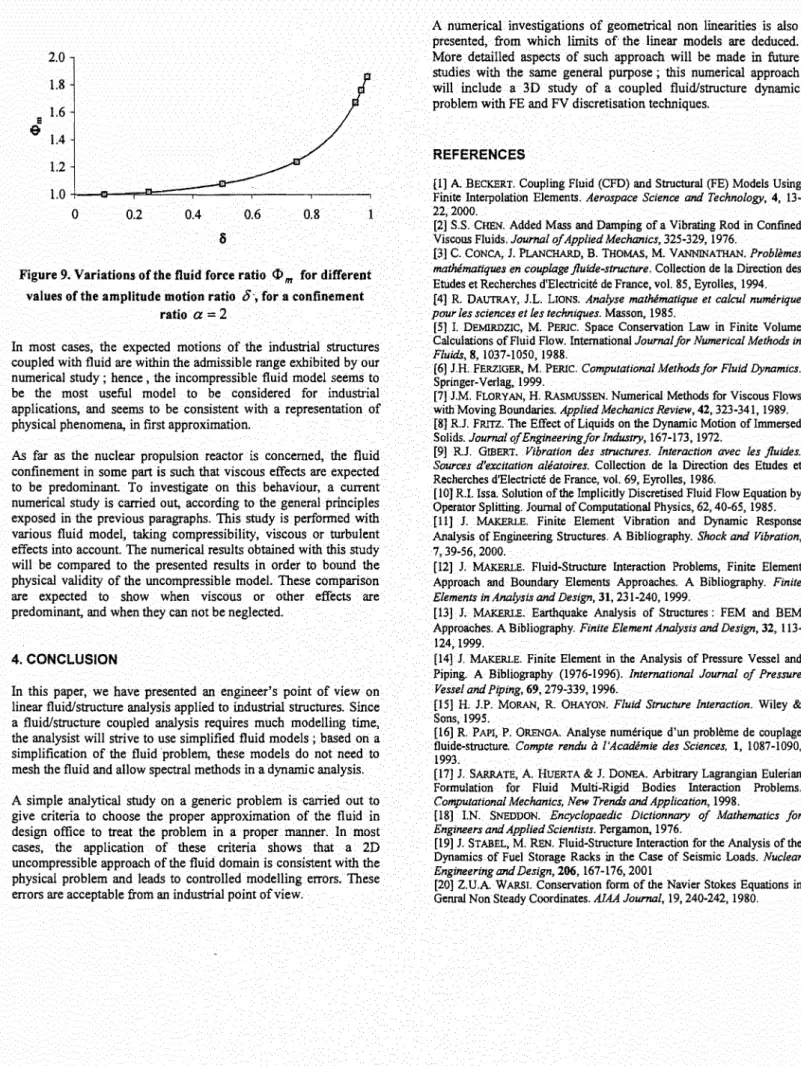
0.8 1Figure 9. Variations of the fluid force ratio <1> m for different values of the amplitude motion ratio
o-,
for a confinementratio
a
=2In most cases, the expected motions of the industrial structures coupled with fluid are within the admissible range exhibited by our numerical study ; hence , the incompressible fluid model seems to be the most useful model to be considered for industrial applications, and seems to be consistent with a representation of physical phenomena, in first approximation.
As far as the nuclear propulsion reactor is concerned, the fluid confinement in some part is such that viscous effects are expected to be predominant. To investigate on this behaviour, a current numerical study is carried out, according to the general principles exposed in the previous paragraphs. This study is performed with various fluid model, taking compressibility, viscous or turbulent effects into account. The numerical results obtained with this study will be compared to the presented results in order to bound the physical validity of the uncompressible model. These comparison are expected to show when viscous or other effects are predominant, and when they can not be neglected.
4. CONCLUSION
In this paper, we have presented an engineer's point of view on linear fluid/structure analysis applied to industrial structures. Since a fluid/structure coupled analysis requires much modelling time, the analysist will strive to use simplified fluid models ; based on a simplification of the fluid problem, these models do not need to mesh the fluid and allow spectral methods in a dynamic analysis.
A simple analytical study on a generic problem is carried out to give criteria to choose the proper approximation of the fluid in design office to treat the problem in a proper manner. In most cases, the application of these criteria shows that a 2D uncompressible approach of the fluid domain is consistent with the physical problem and leads to controlled modelling errors. These errors are acceptable from an industrial point of view.
A numerical investigations of geometrical non linearities is also presented, from which limits of the linear models are deduced. More detailled aspects of such approach will be made in future studies with the same general purpose ; this numerical approach will include a 3D study of a coupled fluid/structure dynamic problem with FE and FV discretisati<>n techniques.
REFERENCES
[I] A BECKERT. Coupling Fluid (CFD) and Structural (FE) Models Using Finite Interpolation Elements. Aerospace Science and Technology, 4, 13· 22,2000.
[2] S.S. CHEN. Added Mass and Damping of a Vibrating Rod in Confined Viscous Fluids. Journal of Applied Mechanics, 325-329, 1976.
[3] C. CONCA, 1. Pl.ANCHARD, B. THOMAS, M. VANNINATHAN. Problemes
mathimatiques en couplage fluide-structure. Collection de Ia Direction des
Etudes et Recherches d'Eiectricite de France, vol. 85, Eyrolles, 1994. (4] R. DAUTRAY, J.L. LIONS. Analyse mathimatique et calcul numerique
pour les sciences et les techniques. Masson, 1985.
[5] I. DEMIRDZIC, M. PERIC. Space Conservation Law in Finite Volume Calculations of Fluid Flow. International Journal for Numerical Methods in
Fluids, 8, 1037-1050, 1988.
[6] JH. FERZIGER, M. PERIC. Computational Methods for Fluid Dynamics.
Springer-Verlag, 1999.
[7] J.M. FLORY AN, H. RAsMUSSEN. Numerical Methods for Viscous Flows with Moving Boundaries. Applied Mechanics Review, 42,323-341, 1989. [8] RJ. FRITZ. The Effect of Liquids on the Dynamic Motion ofimmersed Solids. Journal of Engineering for Industry, 167-173, 1972.
(9] RJ. GIBERT. Vibration des structures. Interaction avec les fluides.
Sources d'excitation aleatoires. Collection de !a Direction des Etudes et
Recherches d'Electricte de France, vol. 69, Eyrolles, 1986.
[ 10] R.I. Issa. Solution of the Implicitly Discretised Fluid Flow Equation by Operator Splitting. Journal of Computational Physics, 62,40-65, 1985. [ll] J. MAKERLE. Finite Element Vibration and Dynamic Response Analysis of Engineering Structures. A Bibliography. Shock and Vibration,
7, 39-56, 2000.
[12] J MAKERLE. Fluid-Structure Interaction Problems, Finite Element Approach and Boundary Elements Approaches. A Bibliography. Finite
Elements in Analysis and Design, 31, 231-240, 1999.
[13] J. MAKERLE. Earthquake Analysis of Structures : FEM and BEM Approaches. A Bibliography. Finite Element Analysis and Design, 32, 113-124,1999.
[14] J. MAKERLE. Finite Element in the Analysis of Pressure Vessel and Piping. A Bibliography (1976-1996). International Journal of Pressure
Vessel and Piping, 69, 279-339, 1996.
[15] H. J.P. MORAN, R. OHAYON. Fluid Structure Interaction. Wiley &
Sons, 1995.
[16] R. PAPI, P. ORENGA. Analyse numerique d'un probleme de couplage tluide-structure. Compte rendu
a
l'Academie des Sciences, 1, 1087-1090, 1993.[17] J SARRATE, A HUERTA & J. DONEA. Arbitrary Lagrangian Eulerian Formulation for Fluid Multi-Rigid Bodies Interaction Problems.
Computational Mechanics, New Trends and Application, 1998.
[18] I.N. SNEDDON. Encyclopaedic Dictionnary of Mathematics for
Engineers and Applied Scientists. Pergamon, 1976.
[ 19] J. ST ABEL, M. REN. Fluid-Structure Interaction for the Analysis of the Dynamics of Fuel Storage Racks in the Case of Seismic Loads. Nuclear
Engineering and Design, 206, 167-176, 2001
[20] Z.UA WARSI. Conservation form of the Navier Stokes Equations in Genral Non Steady Coordinates. A1AA Journal, 19,240-242, 1980.