HAL Id: hal-03100628
https://hal.archives-ouvertes.fr/hal-03100628v2
Preprint submitted on 7 May 2021
HAL is a multi-disciplinary open access
archive for the deposit and dissemination of
sci-entific research documents, whether they are
pub-lished or not. The documents may come from
teaching and research institutions in France or
abroad, or from public or private research centers.
L’archive ouverte pluridisciplinaire HAL, est
destinée au dépôt et à la diffusion de documents
scientifiques de niveau recherche, publiés ou non,
émanant des établissements d’enseignement et de
recherche français ou étrangers, des laboratoires
publics ou privés.
IoTRoam: design and implementation of a federated IoT
roaming infrastructure using LoRaWAN
Sandoche Balakrichenan, Antoine Bernard, Michel Marot, Benoit Ampeau
To cite this version:
Sandoche Balakrichenan, Antoine Bernard, Michel Marot, Benoit Ampeau. IoTRoam: design and
implementation of a federated IoT roaming infrastructure using LoRaWAN. 2021. �hal-03100628v2�
IoTRoam – Design and implementation of an open
LoRaWAN roaming architecture
Sandoche Balakrichenan
1, Antoine Bernard
1,2, Michel Marot
2, and Benoît Ampeau
1 1AFNIC
[email protected]
2
Samovar, Télécom SudParis, Institut Polytechnique de Paris
[email protected]
Abstract—IoT technologies currently operate as independent silos, and roaming is possible only if there are prior intercon-nection agreements. To our knowledge, there are no standard-ised procedures for interconnecting different IoT networks for roaming. The focus of IoTRoam is to set up an operational roaming model that scales, seamlessly embedded to existing IoT infrastructures and interconnects on a global basis with minimum initial configuration requirement. As a Proof-of-Concept, we have designed, implemented and tested a roaming LoRaWAN architecture using time-tested infrastructures in the Internet such as PKI and the DNS. The IoTRoam experience has helped us to propose changes to the LoRaWAN Backend Interface Specification that have been accepted. We also evaluated whether the proposed mechanisms satisfy constrained IoT requirements.
Index Terms—IoT; LoRaWAN; DNS; PKI; AAA
I. INTRODUCTION
Roaming is an End-Device (ED) capability to transmit and receive data on a Visited Network (VN). When roaming outside the Home Network (HN) coverage area, a mobile ED can make and receive calls using the VN infrastructure (such as the radio Spectrum, base station).
Roaming requires an interconnection agreement between the HN and the VN directly or via a third party. Interconnec-tion in IoT becomes possible either by establishing a direct ’One-to-One’ interconnection or using a ’Hub’ model. By establishing an interconnection agreement with a single hub, it is possible to exchange traffic with the peers connected to that hub and the peers’ networks. Both the hub and the One-to-One interconnection models evolve as independent Silos wherein the ED in the coverage area of a VN can connect to its service only if there is a prior interconnection agreement between its HN and the VN or between the HN and the hub.
In the independent silo scenario, when an IoT ED onboards to a VN, bootstrapping trust [1] is a key security concern. The ED needs to be cryptographically authenticated by the VN based on credentials such as its identifier and a Pre-Shared Key (PSK). Cryptography-based authentication usually relies on one or more trust anchors [2]. In the proprietary silo scenarios, the trust anchor information may be preset with the ED or established out of band.
Any architecture proposing solutions to the technology barriers mentioned earlier should take into account the con-strained characteristics of IoT environments. As a benchmark,
we propose to validate our architecture on one of the most constrained IoT network - Long Range Wide Area Network (LoRaWAN). If the proposed architecture is validated with LoRaWAN having constraints such as the maximum frame size of 51 bytes (or 222 bytes for lower spreading factors) and latency requirements of two seconds for default uplink/-downlink, we hypothesise that architecture is extendable to other IoT networks.
In LoRaWAN, there are three types of networks: public, private and community. Mobility between these different net-works is of importance. A company may use LoRaWAN to monitor the battery level of vehicles in its fleet, an agricultural cooperative may use LoRaWAN to monitor the stock flows of its associates or an emergency service may use LoRaWAN to coordinate its teams in the field. Most existing studies on LoRaWAN consider scenarios where the EDs’ are mobile but remain under the umbrella of the same network server [3].
The IoTRoam architecture aims to enable interoperability between the silos in the IoT domain by leveraging the Domain Naming Service (DNS) protocol, its security extensions (DNS Security Extensions (DNSSEC)) and the Public Key Infras-tructure (PKI) using self-signed X.509 digital certificates, thus bringing in the following contributions:
• The proposed architecture enables roaming between dif-ferent LoRaWAN networks without the need of having any prior interconnection agreement
• The architecture includes an Authentication and Autho-rization (AA) framework based on PKI enabling secure onboarding of the IoT ED
• The architecture satisfies basic IoT operational
require-ments such as scaling, viability by not incurring addi-tional costs, able to be deployed immediately, interoper-able between different IoT networks involving multiple stakeholders
• Experiences from the implementation as a Proof of Con-cept (PoC) has enabled us to propose three acCon-cepted change requests (Change request is the procedure to provide modifications to the LoRaWAN specifications)
• With this PoC we tested different LoRaWAN roaming scenarios with two Institutions in France - IMT Atlan-tique and Telecom Sud Paris (TSP). We ran measure-ments to assess whether the additional overhead
intro-duced by the proposed architecture meets the constrained requirements of LoRaWAN
IoTRoam’s added value is the possibility of using core In-ternet infrastructures such as DNS and PKI to enable intercon-nection and security of IoT ED onboarding. The objective is to extend Internet resolution and security infrastructure services to be adapted to IoT, thus enabling seamless interoperability.
The remaining parts of this paper are structured as follows: Based on the literature, Section II identifies the requirements for a secure and seamless interconnection architecture. In Section III, we argument our design choices and Section IV describes how DNS and PKI are deployed and validated for LoRaWAN passive roaming. In Section V, we evaluate whether the proposed mechanisms satisfy LoRaWAN con-straints and finally sum up our contributions and conclusion in VI.
II. RELATEDWORK
When an IoT ED is roaming, the VN should retrieve its identifier from the incoming Join Request (JR) packet to identify the ED’s HN. Therefore, identifiers play a vital role in IoT interconnection [4] [5]. IoT identifiers are structured into two different categories: Hierarchical and Flat. An example of a hierarchical identifier is the Electronic Product Code (EPC) [6]. The barcodes attached to consumer products are based on EPC identification. An example of a flat identifier is the Unique Device Identifier (UDID), a unique serial number assigned to track and record each Apple manufactured device. Both Apple and the EPC identity management infrastructures use closed databases to provision the identifiers. Mapping the ED’s identifier to its appropriate network or service is only possible by entities who are provided access to these databases. From a global (not just limiting to LoRaWAN) IoT perspective, the first issue to resolve is to let different IoT sectors use their existing identifiers but to use a global database for IoT allocation and resolution.
The second issue is to use a global AA model, which control the terms under which a roaming ED is allowed to securely use the resources in the environments operated by the VN. AA functionalities are usually consolidated in a single centralized database [7]. The centralized AA framework has its advantages and significant disadvantages, such as creating a single point of failure. Blockchain using distributed ledger has been ex-perimented with and deployed [8][9] to accomplish a scalable decentralized AA framework. Nevertheless, the blockchain model has several drawbacks as a feasible operational model [10] in an open/global scenario.
A third technology barrier that we consider is that any proposed architecture should satisfy IoT environment con-straints requirements. IoT connectivity technologies could be classified broadly into three categories [11]: Short Range (Bluetooth, Zigbee, Zwave), Medium range (Wi-Fi) and Long-range (LoRa, NB-IoT, Wi-Sun, Sigfox). We eliminated from our focus, technologies that cannot support roaming, such as Short-Range technologies and closed networks such as Sigfox, which does not require the roaming feature due to its vertical
ecosystem. Narrowing our focus on requirements, we short-listed LoRaWAN due to its open standard characteristics and its ability to set up a private roaming set up.
The DNS infrastructure is used to interconnect domain names and IP address and is scalable and operationally viable in the Internet. Standards such as Object Naming Service [12] for the consumer industry, Object Resolution System standard-ised jointly by the ITU-T and ISO/IEC, and the Handle system standardised by the ISO uses the DNS infrastructure to resolve the IoT identifiers to its related service in the Internet. DNS has been used by Mobile Network Operators (MNOs) on the inter-operator IP backbone network to enable data roaming [13].
eduroam [14], a Wi-Fi based roaming platform widely adopted in the academic environment uses a distributed PKI based on X.509 digital certificates for AA. The trust fabric in eduroam is a PSK between the RADIUS servers (organi-sational, national, global) based on the DNS hierarchy. Such a trust fabric, wherein a PSK is shared hierarchically, is a hindrance to the design that we envision for IoTRoam. Differ-ent IoT networks use differDiffer-ent mechanisms to share the PSK between the ED and the AA servers in the Internet to securely onboard the ED to its HN. Forcing them to transition to a newly proposed PSK mechanism is not operationally possible since multiple stakeholders are involved. We proposed to use the PKI based on X.509 self-signed digital certificates and DNSSEC trust anchor fabric that allows the IoT stakeholders to use their existing PSK mechanism.
III. IOTROAM ARCHITECTURE– DESIGNCHOICES
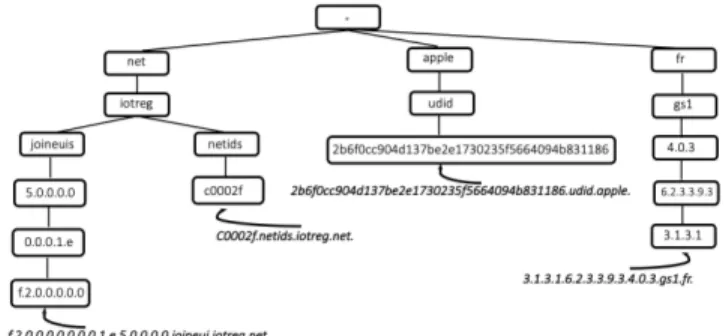
Both previously mentioned IoT identifier types, hierarchical (EPC) and flat (UDID), could be accessed from the global Internet if they are provisioned in the global DNS database (Figure 1). Then it is up to the client libraries to make the conversion and add the specific sub-domain suffix (apple for UDID and gs1 for EPC) to the identifiers. Once the identifier is converted to a domain name as follows:
2b6f0cc904d137be2e1730235f5664094b831186.udid.apple. 3.1.3.1.6.2.3.3.9.3.4.0.3.gs1.fr.
they will follow the normal DNS resolution process to resolve the identifier’s associated resource/service/metadata globally.
Some parameters such as ED’s HN identity, the AA server identity, the authentication credentials and the port numbers must be configured in proprietary roaming models such as a hub before an ED can roam outside its HN. Except for the authentication credentials, all other information could be retrieved from the DNS database. Thus, by provisioning their IoT identifiers and related information in the DNS database under their own domain namespace, different IoT sectors could interoperate by using their existing identifiers, thus satisfying operational viability.
The ED is configured with a PSK (Symmetric Key) that is only shared with an AA server, creating the session keys for encrypted communication between the ED and the different
Figure 1: Provisioning IoT identifiers in the Internet domain namespace
associated servers in the Internet. When the ED is onboarding in a VN, the VN should establish mutual authentication with the ED’s AA servers and the HN. To establish mutual authentication dynamically between different servers on the Internet managed by multiple stakeholders, our hypothesis is to use the DNSSEC infrastructure as trust anchors and the Public Key Infrastructure based on self-signed X.509 digital certificates. The DNSSEC extensions use asymmetric cryptographic signature mechanisms to authenticate the data provisioned in the DNS database. The Signatures and public keys come in the form of new DNS records that provide authentication. With DNSSEC, the origin and integrity of received data can be verified using one or more key pairs associated with the DNS zone.
DNS is a time-tested infrastructure and had scaled from hundreds of domains from the Internet’s beginning to billions currently [15]. These factors influenced our choice to use the DNS infrastructure, its security extensions and PKI in the LoRaWAN roaming architecture.
IV. EXPERIMENTSETUP ANDVALIDATION
A. Brief LoRaWAN background
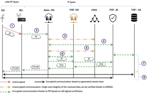
LoRaWAN is an asymmetric protocol built on a star topol-ogy as shown in Figure 3. Data transmitted by the ED is received by a Radio Gateway (RG), which relays it to a Network Server (NS). The NS has multiple responsibilities like forwarding the uplink from the ED to the Application Server (AS), queuing the downlink from the AS to the ED, forwarding the ED onboarding request to the appropriate AA servers, named as Join Server (JS) in LoRaWAN terminology. While the ED is connected to the RG via LoRa modulated RF messages, the connection between the RG, the NS, the JS and the AS is done through IP traffic and can be back-hauled via Wi-Fi, hardwired Ethernet or Cellular connection.
LoRaWAN specifications use JoinEUI, a global application ID in IEEE EUI64 address space, to uniquely identify the JS and NetID, a 24-bit value assigned by the LoRa Alliance uniquely identifying the NS. The ED is uniquely identified by DevEUI.
B. Using the DNS infrastructure for Identifier allocation and resolution
A DNS infrastructure was set up under the domain iotreg.net for provisioning the JoinEUIs and NetIDs, as shown in Figure 1. Each nibble of the JoinEUI represented in the hexadecimal format 0x00005E100000002F is first reversed. Then, peri-ods are inserted between each nibble and the domain name joineuis.iotreg.net is concatenated as the suffix. The final result is a domain name provisioned in the DNS database pointing to their respective JS as follows:
f.2.0.0.0.0.0.0.0.1.e.5.0.0.0.0.joineuis.iotreg.net. IN A 192.168.1.1
Similar to the JoinEUI, the NetID represented in the hexadecimal format are provisioned into the DNS without reversing and adding periods between each digit, pointing the allocated NetID to its NS is as follows:
c0002f.netids.iotreg.net. IN A 192.168.1.2
The JoinEUI is reversed, and periods are added since it benefits from a hierarchical model and the NetID is based on the flat model.
The DNS provisioning mechanism has ensured that both JoinEUI and NetID could be provisioned or updated by different entities in their respective DNS Zones (Servers); they are unique in the global scope and cannot be duplicated. Both JS and the NS can be accessed from anywhere in the Internet and with a simple DNS resolution, the JoinEUI can be resolved to its JS and NetID to its NS dynamically without any prior interconnection agreements shared in advance. The JS and the NS DNS resolution information are secured from data being spoofed on the wire being modiifed at the DNS database, since the DNS infrastructure is signed by DNSSEC.
We developed and provided a secure, automatized DNS pro-visioning platform that could be used by the community. Any authorized user can access the User Interface (UI) (via web or API) with a secured API key. The UI enables authorized users to do multiple operations (creation, modification, deletion) of only their data in the DNS database. To make it easy for the community to understand and use the interface, a Video Tutorial [16] is provided.
While testing the UI with some LoRa Alliance community members, we encountered operational issues such as: how to validate the data provisioned in the DNS is done by the rightful owner. The need for validating the JoinEUI (which is a IEEE EUI-64 identifier provisioned by the IEEE and has Organisa-tional Unique Identifier (OUI) in the IEEE EUI-64) with the IEEE OUI database, were identified and implemented, thanks to the PoC. The implemented solution has been provided as feedback to the LoRa Alliance, which could be integrated when the DNS service operated by the LoRa Alliance is deployed.
There was no existing off-self or open source LoRaWAN network stack software that uses DNS for ED onboarding or roaming. We collaborated with the open-source Chirpstack network stack [17] author to update the software to integrate
both functionalities. The NS, JS and the AS in our PoC are installed with appropriate software from Chirpstack, thus enabling DNS resolution.
C. PKI integration
For secure ED onboarding, the interface between the servers (NS, JS and the AS which could be grouped as backend elements) in the IP space (Figure 3) should be mutually authenticated (i.e., both the client and the server authenticate each other), as per the LoRaWAN Backend Interface Specifica-tion [18]. However the mechanisms for mutual authenticaSpecifica-tion is left to the implementer’s choice and is not normative.
The PKI using the X.509 digital certificates signed by a trusted Certificate Authority (CA) is widely used to secure web traffic. However, the CA trust model for issuing the X.509 digital certificates is not operationally feasible for IoTRoam. In the web, the browser client (such as Chrome, Firefox) has a certificate store containing thousands of Root CA certificates. The browser authenticates any server that delivers a X.509 certificate digitally signed by anyone of the Root CA in its certificate store. Such certificate store infrastructure is not available in the LoRaWAN backend network elements or any IoT backend infrastructures. Even if we assume the infrastructure exists, the digital certificates come at a cost, which is not viable for most IoT services. We tried with Let’s encrypt, which provides X.509 digital certificates for free. However, it was not possible to benefit since they do not provide certificates for domain names with more than 10 labels (JoinEUI has more than 16 labels). A viable solution to resolve the operational and cost issue is to generate our Self-Signed certificates.
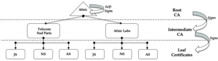
Figure 2: IoTRoam Certificate provisioning infrastructure Our Certificate provisioning model is that any Institution willing to test roaming based on the IoTRoam architecture can request intermediate certificates from a trusted root CA. Figure 2 shows a scenario wherein Afnic plays the role of root CA and generates intermediate certificates for two independent LoRaWAN networks - TSP & Afnic Labs. The intermediate CAs will, in turn, generate the leaf certificates for backend elements.
Details on obtaining an Intermediate Certificate and gen-erating the leaf certificates are documented [19]. We further simplified the process, wherein the Institutions can generate the leaf certificates by just running a makefile after customis-ing their JSON configuration files and addcustomis-ing the provided leaf certificates information into each of the backend elements configuration file.
D. Architecture Validation
To validate the architecture, two independent LoRaWAN networks were set up separated by a distance of 34 kilometres. The two locations are Afnic (in the Yvelines department in France) and TSP (in the Essonne department in France). The backend elements are installed with the open-source Chirp-stack network Chirp-stack and are configured with their respective intermediate and leaf certificates.
Figure 3 shows that the ED configured with TSP as HN uses the RG in Afnic’s coverage area to onboard (Step 1). The RG forwards (Step 2) the incoming JR to the Afnic NS, which in turn uses the DNS infrastructure (Step 3) to retrieve the TSP-JS IP address (based on the JoinEUI in the JR) since the ED is unknown to it. Afnic-NS and the TSP- JS runs a TLS handshake for mutual authentication (Step 4). During mutual authentication testing, we identified that combining the intermediate and the server leaf certificate (a combined trust chain) during a TLS handshake could bypass the need for having a certificate store with all intermediate certificates and store only the root CA certificate. The certificate validation process is done by sending the combined trust chain to the server’s IP address. On receiving the combined trust chain, the server first verifies the leaf certificate in the combined trust chain. When the leaf certificate is unknown, it checks the following certificate in the chain, the intermediate certificate. Since the intermediate certificate is signed by the root CA the combined certificate chain becomes trusted. Thus, the backend network elements (NS, AS and the JS) could be mutually authenticated even if they are in different networks since they have a common root CA at the top of the chain of trust.
On a successful mutual authentication between the Afnic-NS and the TSP-JS, Afnic-Afnic-NS retrieves the NetID of the ED from the TSP-JS (Step 4). Using the retrieved NetID, the IP address of the ED’s NS (i.e., TSP-NS) is obtained (Step 5) via DNS resolution, and mutual authentication is established between the Afnic-NS and TSP-NS (Step 6). Once the mutual authentication is established between the different servers in the IP interface, the JR is sent to the TSP-JS to create the cryptographic session keys. The cryptographic session keys are sent back to the ED via the PKI secured mutual authentication channel as Join Answer (JAns) and Join Accept (JAccept) (Step 7). Finally, a secured session between the ED and the associated servers in the Internet using the generated session keys (Step 8).
V. PERFORMANCE EVALUATION
The time taken for the ED to onboard (i.e. Steps 1-7 in Figure 3) is the first metric that we want to measure to study the latency influences by DNS and PKI. Following an uplink, a Class A ED in LoRaWAN opens a receive window for 1 second (default value) and if no downlink is received during the period, it opens a second receive window for another second (default value). If no downlink communications are received from the server between the two-receiver window, then it must wait until the ED triggers the next uplink and opens a receive window. The second metric we measured is to
Figure 3: Testing Passive roaming ED onboarding using the proposed architecture
check whether the two second receiving window requirement is satisfied even after the introduction DNS and PKI.
We defined three scenarios to measure the two metrics:
• Scenario 1: The ED is in the HN without the latency introduced by DNS or PKI
• Scenario 2: The ED is in the HN, but the NS and JS are resolved using DNS resolution
• Scenario 3: The ED is in the VN’s coverage area with
the latency introduced by DNS and PKI for mutual authentication
Figure 4: Cumulative distribution of the ED onboarding delay measured on the ED in ms
To ensure that the measurement is precise and get rid of any synchronization error between the ED and the backend network elements, the measurements were realised directly on the ED. We ran the measurements for around 30 hours of transmissions and gathered more than 2000 measurements for each scenario.
Figure 4 shows the time-to-join for the three scenarios, obtained by monitoring the delay between the JR and the “Join Success” message received at the ED. In the EU 868 Mhz channel plan for LoRaWAN, the Join Delay window is 5 seconds [20] meaning the gateway will transmit the downlink JAccept exactly 5s after the uplink. The gateway may receive the downlink JAccept well in advance, but it will stay in the queue until the requested TX time. This means that the ED will receive the JAccept after 5s. Our measurements show that in all scenarios, the device receive its JAccept around 90% of the time around 5.2s after sending its JR. The ED is able to onboard as soon as possible regardless of the use of DNS or the fact that the ED is roaming. Therefore, DNS seems to have no significant impact on the activation delay. A fact which can be explained considering that the ED’s Join Delay is significantly lower than the standard times for DNS resolutions (usually around 300ms).
Figure 5: Cumulative distribution of the first uplink delay measured on the ED in ms
Figure 5 shows the first delay for an end-to-end commu-nication after activation. Once again we see that our data is gathered around two values, 1.2s and 2.4s, which correspond to the two receive windows available when class A LoRaWAN ED communicate. The ED is able to receive the acknowledge-ment within the receive window’s time limit regardless of the scenario studied.
These measurements lead us to believe that introducing DNS and PKI to the LoRaWAN system would not significantly add to the latency in LoRaWAN communications. It is of note that when working on our measurements we configured our infrastructure to work without DNS caching. A regular infrastructure would further benefit from DNS caching as a way to reduce the impact of DNS[21].
VI. CONCLUSION, CONTRIBUTION ANDFUTURE WORK
Our objective with IoTRoam is to achieve the same ser-vice as that of cellular or Wi-Fi Roaming built on a global resolution and security infrastructure, namely the DNS and PKI. We added a hard requirement that the infrastructure or technologies used to achieve this vision should be viable, operationally feasible and could be integrated to existing IoT infrastructures with minimum changes. We chose LoRaWAN (an evolving standard) and demonstrated that seamless IoT roaming with minimum prior configuration is possible using the IoTRoam architecture. In this process we have deployed a PoC and provided all necessary building blocks (documen-tation, software, UI, video tutorial) so that each one in the community could make use of them to implement his own network.
This experience has also helped us to propose three Change Requests, that have been adopted into the LoRaWAN Backend Interface Specification. The first one includes the possibility of using any DNS resource record ED activation and roaming functionalities. The second is the creation of a combination of the DevEUI (which is unique for each ED) and JoinEUI, and provision them in the DNS. This solution was proposed to resolve the device manufacturer’s issue of providing the ED’s configured in the same batch with same JoinEUI and different DevEUI to be sold to different buyers. The third includes modifying the domain names for join and roaming from lora-alliance.org to lorawan.net, thus segregating the LoRa Alliance Web and DNS service.
As the objective is to interconnect networks using different IoT technologies, we intend to test roaming interoperability with NB-IoT and 5G. For ED onboarding, we are also working on integrating DNS Authentication of Named Entities (DANE) with DNSSEC since the certificate data itself can be stored in the DNS, possibly obsoleting the PKI.
VII. ACKNOWLEDGEMENTS
We want to acknowledge Orne Brocaar, the author of Chirpstack LoRaWAN network stack who has helped us to update the Chirpstack network stack to enable DNS based resolution; Prof. Monique Becker for her valuable feedbacks and also the LoRaWAN community where we were able to
gain insights on real operational issues. This research has been partially funded by ANR project DiNS under contract ANR19-CE25-0009-01.
REFERENCES
[1] Sethi M., Sarikaya B., and Garcia-Carrillo D. Se-cure IoT Bootstrapping: A Survey, draft-sarikaya-t2trg-sbootstrapping-11. Tech. rep. IETF, 2021.
[2] Susan Symington, William Polk, and Murugiah Soup-paya. Trusted Internet of Things (IoT) Device Network-Layer Onboarding and Lifecycle Management. Tech. rep. NIST, 2020.
[3] Jansen Liando et al. “Known and UnknownFacts of LoRa: Experiences from a Large-scale Measurement Study”. In: ACM Transactions on SensorNetworks (2019).
[4] Identifiers in Internet of Things (IoT). 2018.
[5] Haris Aftab et al. “Analysis of identifiers in IoT plat-forms”. In: Digital Communications and Networks 6.3 (2020), pp. 333–340.
[6] EPC Tag Data Standard.
[7] B. Stackpole. “Centralized authentication services (RA-DIUS, TACACS, DIAMETER)”. In: Sixth. Information Security Management Handbook, Jan. 2007, p. 909. [8] Ali Dehghantanha Kim-Kwang Raymond Choo, ed.
Blockchain Cybersecurity, Trust and Privacy. Vol. 79. Springer, 2020.
[9] "Na Shi et al. “A Blockchain-Empowered AAA Scheme in the Large-Scale HetNet”. In: "Digital Communica-tions and Networks"(2020).
[10] Distributed PKI vs Traditional PKI. https://dzone.com/ articles/distributed-pki-vs-traditional-pki. June 2020. [11] WBA-IoT-Dynamic-Roaming. WBA White paper. https:
//wballiance.com/iot-interoperability-and-roaming-iot-dynamic-roaming/. December 2019.
[12] Object Naming Service. https : / / www. gs1 . org / sites / default/files/docs/epc/ons_2_0_1- standard- 20130131. pdf. 2013.
[13] EPS Roaming Guidelines Version 22.0. 2020. [14] Eduroam Website. https://www.eduroam.org/.
[15] Approximative number of websites. https : / / www . internetlivestats.com/total-number-of-websites/. 2018. [16] Video Afnic. https://iot.rd.nic.fr/Video/version3.mp4.
2020.
[17] ChirpStack Website. https://chirpstack.io/. 2020. [18] LoRaWAN® Backend Interfaces Technical Specification
(TS002-1.1.0). https : / / lora - alliance . org / wp - content / uploads/2020/11/TS002- 1.1.0_LoRaWAN_Backend_ Interfaces.pdf.
[19] IoTRoam PoC. https : / / github . com / afnic / IoTRoam -Tutorial/. 2020.
[20] Farrell, S., Ed. “"Low-Power Wide Area Network (LP-WAN) Overview", RFC 8376”. In: (May 2018). [21] Jaeyeon Jung et al. “DNS performance and the
effec-tiveness of caching”. In: IEEE/ACM Transactions on Networking10.5 (2002), pp. 589–603.