MANUSCRIPT-BASED THESIS PRESENTED TO ÉCOLE DE TECHNOLOGIE SUPÉRIEURE
IN PARTIAL FULFILLMENT OF THE REQUIREMENTS FOR THE DEGREE OF DOCTOR OF PHILOSOPHY
Ph. D.
BY
Ammar HAMAD
PERFORMANCE ANALYSIS AND MANAGEMENT OF RPR (RESILIENT PACKET RING) RINGS ATTACHED TO A NEW LARGE LAYER 2 (L2) NETWORKS (NLL2N)
MONTREAL, JUNE 27, 2016
c
M. Michel Kadoch, thesis director
Department of Electrical Engineering, École de technologie supérieure (ETS)
M. David Bensoussan, member
Department of Electrical Engineering, École de technologie supérieure (ETS)
Ms. Sylvie Ratté, committee president
Department of Software Engineering and IT, École de technologie supérieure (ÉTS)
M. Hamid Mcheick, external examiner independent
Department of Computer Sciences and Mathematics, Université du Québec à Chicoutimi (UQC)
THIS THESIS WAS PRESENTED AND DEFENDED
IN THE PRESENCE OF A BOARD OF EXAMINERS AND THE PUBLIC ON APRIL 19, 2016
whom I have learned a lot.
I am very grateful to my wife Rosy (she supported me all the time, she is a great wife), my daughter Sara, my son Karim and my “granddaughter” Mia.
I dedicate this thesis to my father Mohamed and my mother Zina for the great value and edu-cation that they gave me. God bless them!
Ammar HAMAD RÉSUMÉ
Les volumes de trafic Internet se développent, nécessitant une capacité de transmission de plus en plus importante et provoquant une croissance de l’infrastructure. Le trafic Internet crois-sant exige également une gestion bien contrôlée et le maintien d’une bonne performance. Un examen plus approfondi révèle que l’infrastructure de l’Internet repose sur une architecture hiérarchique à trois niveaux. Elle est constituée des réseaux dorsaux, des réseaux métropoli-tains et des réseaux d’accès locaux. Les réseaux métropolimétropoli-tains (MAN), ou les réseaux métros pour simplifier le nommage, interconnectent les réseaux de base avec les réseaux d’accès lo-caux qui, eux, transportent les données de et vers les utilisateurs individuels. En employant des technologies avancées des réseaux locaux (LAN) tel que Gigabit Ethernet (GbE), l’accès à large bande tel que la boucle d’abonné numérique (DSL) et les câbles modems. Les réseaux d’accès fournissent des quantités croissantes de bande passante. La plupart des réseaux de métro existantes sont basées sur des réseaux optiques synchrones, la technologie hiérarchique synchrone (SONET / SDH) et la technologie de réseau à commutation de circuits. Semblable à des commutateurs Ethernet, mais tout à fait différent des multiplexeurs (insertion/extrac-tion) de SONET/SDH, les commutateurs RPR peuvent être débranchés et retirés de réseau d’une façon dynamique. Aucune préparation n’est nécessaire et rien de plus que quelques millisecondes est nécessaire pour remettre le réseau en service en cas de panne. RPR et Eth-ernet ont beaucoup de points communs. L’interface MAC de RPR, dans son utilisation par défaut, est exactement la même que le MAC d’Ethernet. Les trames de RPR ressemblent beau-coup aux trames d’Ethernet, avec quelques champs de plus. Tout service qui tourne au-dessus d’Ethernet fonctionne également au-dessus de RPR. De la même manière, tout service fournit par Ethernet est également fourni par RPR. Ethernet et RPR fonctionnent, dans des réseaux commutés, de façon transparente. RPR est étroitement aligné avec Ethernet et complètement interopérable avec d’autres MAC 802. RPR a été implémenté dans les réseaux locaux et les réseaux métropolitains et il fonctionne adéquatement, cependant il n’a pas été implémenté ou testé avec un grand réseau niveau 2 (Modèle OSI). Avoir les anneaux RPR attachés directement à un grand réseau «Layer 2», comme SONET / SDH, Ethernet, Gigabit Ethernet, sera un défi intéressant car cela va nous permettre d’adapter RPR à tous ces réseaux de niveau 2 (Couche 2 de Modèle OSI).
Dans notre recherche, nous proposons une autre alternative pour concevoir des réseaux métropoli-tains (MAN), des réseaux locaux (LAN) ou des réseaux étendus (WAN). RPR sera déployé comme la dorsale de réseau du transport. RPR sera attaché directement à différents réseaux de niveau 2. Il pourrait être placé entre deux réseaux SONET / SDH ou entre deux segments Gigabit Ethernet et ainsi de suite. Le nouveau grand réseau ou la grande configuration que
nous proposons sera nommé: le Niveau 2 Nouveau Grand Réseau (New Large Layer 2 Net-work (NLL2N)). Nous allons utiliser les anneaux RPR pour interconnecter divers topologies dans un campus ou dans un environnement d’entreprise ce qui fournira une valeur à ajouter pour le client et apportera un transporteur de qualité dans leur infrastructure de réseau. Du-rant notre recherche, nous allons investiguer RPR sur Ethernet (RPRoE), RPR sur SONET (RPRoSONET), SONET sur Ethernet (SONEToE) et nous allons démontrer que RPR, Ether-net et SONET pourraient être intégrés dans le même réseau de niveau 2. Nous allons expliquer et détailler l’utilisation de RPRoE, de SONEToRPR et l’intégration de chacun d’eux pour créer un nouveau grand réseau de niveau 2 (NLL2N). Nous allons également souligner les avantages de celui-ci. La gestion et la performance de notre architecture proposée, ainsi que sa perfor-mance pour diverses configurations de réseau avec différents scénarios de trafic, seront évaluées par le biais de l’analyse des expériences et des simulations.
Mots clés: Traffic Internet, Capacité de transmission, Réseau dorsale, Réseau Local, Réseau métropolitain, Réseau commuté , Réseau de transport, Giga Ethernet, Trame Ethernet, Modèle OSI, Gestion de performance, Simulation, Analyse
Ammar HAMAD ABSTRACT
The volume of Internet traffic is growing, which calls for the transmission capacity of the un-derlying infrastructure to be continuously extended. It also requires a tide management which can maintain a good performance. A closer look at Internet infrastructure reveals that it archi-tecturally relies on a three level hierarchy consisting of backbone networks, metropolitan area networks, and local access networks. The Metropolitan Area Networks (MANs), or metro net-works for short, interconnect the backbone netnet-works with the local access netnet-works that carry the data from and to the individual users. By employing advanced Local Area Network (LAN) technologies (i.e., Gigabit Ethernet (GbE)), and broadband access, (i.e., Digital Subscriber Loop (DSL) and cable modems), access networks provide increasing amounts of bandwidth. Most existing metro networks are based on Synchronous Optical NETwork/Synchronous Digi-tal Hierarchy (SONET/SDH) technology, a circuit-switched networking technology. Similar to Ethernet switches, and quite unlike SONET/SDH add/drop multiplexers, RPR switches can be plugged into and removed from a ring dynamically. No advance provisioning is required and nothing more than a few milliseconds of outage is resulted. RPR and Ethernet share a lot in common. RPR’s logical MAC interface, in its default usage, is exactly the same as Ethernet’s. RPR’s frames look very similar to Ethernet frames, with slightly more fields added. Any ser-vice that runs on top of Ethernet also runs on top of RPR. Every serser-vice that Ethernet provides is also available by RPR. Ethernet and RPR work together seamlessly in bridged/switched networks. RPR is closely aligned with Ethernet and completely interoperable with other 802 MACs. RPR has been implemented in LAN and MAN network and works adequately, but it has not been implemented or tested with a large L2 network. Having RPR rings attached directly to a large L2 networks, of different types of SONET/SDH, Ethernet, and GbE will be an interesting challenge because we have to adapt RPR rings to all these L2 networks. In our research, we are proposing an alternate way to design campus (MAN), Local Area Network (LAN) and Wide Area Network (WAN). And, to employ RPR rings for the backbone transport. RPR rings will be attached directly to a different L2 networks. It could be placed between two SONET/SDH rings or between two GbE segments and so on. Our new large networks or large configurations that we propose will be named: New Large L2 Network (NLL2N). Us-ing RPR rUs-ings to interconnect various locations on a campus or in an enterprise environment provide a superior value to the customer and bring Carrier Ethernet qualities to the backbone transport network. During our research, we will investigate RPR over Ethernet (RPRoE), RPR over SONET (RPRoSONET), SONET over Ethernet (SONEToE) and we will demonstrate that RPR, Ethernet, and SONET could be integrated together in the same Layer 2 Network. In our research we will explain and detail the use of RPRoE and SONEToRPR, and the integration of all of them to create a New Large Layer 2 Network (NLL2N) and point out the benefits
of it. We comprehensively evaluate the management and the performance of our proposed ar-chitecture, as well as, the underlying performance enhancing techniques for various network configurations and traffic scenarios, by means of experiments analysis and simulations.
Keywords: RPR bridging, RPR rings, RPR switching, RPR frame, Transiting frame, Gigabit Ethernet, Local Area Network, MAC address, Physical layer, MAC layer, SONET/SDH, Short-est path routing, Committed information, Excess information rate, Fairness algorithm, Re-served, Reclaimable, Packet optimization, TDM traffic, Quality of Service, New Large Layer 2 Network, Address learning
INTRODUCTION . . . 1
CHAPTER 1 LITERATURE REVIEW . . . 5
1.1 Optical WDM Communications Networks . . . 5
1.1.1 Progress and challenges . . . 5
1.1.2 What Worked and What Did Not . . . 6
1.1.2.1 What Worked . . . 6
1.1.2.2 What Did not work . . . 7
1.2 Overview of The Optical Broadband Access Evolution . . . 8
1.3 Metropolitan Area Packet-Switched WDM Networks . . . 9
1.3.1 RINGO . . . 10
1.3.2 HORNET . . . 11
1.4 IEEE 802.17 Resilient Packet Ring (RPR) [Davik et al. (2004)] . . . 13
1.4.1 Fundamentals of RPR . . . 13
1.4.2 Station design and packet priority . . . 15
1.4.3 MAC protocol . . . 17
1.4.3.1 Ring access . . . 17
1.4.3.2 Fairness control . . . 19
1.4.3.3 Resilience . . . 21
1.4.4 Strengths and weaknesses of RPR . . . 22
1.5 Synchronous Optical NEtwork (SONET) [IEC] . . . 24
1.5.1 Introduction to SONET . . . 24
1.5.2 Rates and formats . . . 24
1.5.2.1 Typical End-to-End Connection . . . 24
1.5.3 Frame Structure . . . 25
1.5.4 Overheads . . . 26
1.5.5 SONET Multiplexing . . . 28
1.5.6 Ring Architecture . . . 29
1.6 Gigabyte Ethernet (GE) [CIS, Chitti et al. (2015)] . . . 30
1.6.1 Introduction . . . 30
1.6.2 Standards Evolution . . . 31
1.6.3 Gigabit Ethernet Protocol Architecture . . . 31
1.6.4 Physical Interface . . . 32
1.6.5 Media Access Control Layer . . . 33
1.6.6 Example of Implementation . . . 34
CHAPTER 2 OBJECTIVES OF RESEARCH AND ORIGINALITY . . . 37
2.1 Objectives of Research . . . 37
2.1.1 Problem Statement . . . 37
2.2 Methodology . . . 38
CHAPTER 3 RPR OVER ETHERNET . . . 41
3.1 Introduction . . . 41
3.2 Fundamentals of RPR . . . 42
3.3 Station Design and Packet Priority . . . 43
3.4 Fundamentals of Gigabyte Ethernet . . . 46
3.4.1 Standard evolution . . . 47
3.4.2 Gigabit Ethernet Protocol Architecture . . . 47
3.5 Basic Principles of RPR Over Ethernet . . . 49
3.5.1 Address learning of RPR over Ethernet . . . 50
3.5.2 RPRoE Simulation . . . 51
3.5.3 Advantages of RPRoE . . . 52
3.6 Conclusion . . . 55
CHAPTER 4 SONET OVER RPR . . . 57
4.1 Introduction . . . 57
4.2 Fundamentals of SONET . . . 58
4.2.1 Introduction to SONET . . . 58
4.2.2 Frame Structure . . . 58
4.3 FUNDAMENTALS OF RPR . . . 60
4.4 Station Design and Packet Priority . . . 61
4.5 Basic Principles of SONET Over RPR . . . 64
4.5.1 Goals for SONET over RPR . . . 65
4.5.2 SONEToRPR Simulation . . . 66
4.5.3 Advantages of SONEToRPR . . . 70
4.5.4 Performance analysis of SONEToRPR . . . 70
4.6 Conclusion . . . 71
CHAPTER 5 SONET OVER ETHERNET . . . 73
5.1 Introduction . . . 73
5.2 Fundamentals of SONET . . . 74
5.2.1 Introduction to SONET . . . 74
5.2.2 Frame Structure . . . 74
5.2.3 SONET Multiplexing . . . 74
5.3 Fundamentals of Gigabit Ethernet . . . 76
5.3.1 Standard evolution . . . 77
5.3.2 Gigabit Ethernet Protocol Architecture . . . 77
5.4 Basic Principles of SONET Over Ethernet . . . 79
5.4.1 Address learning of SONET over Ethernet . . . 80
5.4.2 SONEToE Simulation . . . 80
5.4.3 Advantages of SONEToE . . . 82
CHAPTER 6 USING RPR, ETHERNET, AND SONET TO CREATE A NEW
LARGE LAYER 2 NETWORKS (NLL2N) . . . 85
6.1 Introduction . . . 85
6.2 Fundamentals OF RPR . . . 86
6.2.1 Station design and packet priority . . . 87
6.3 Fundamentals OF Gigabit Ethernet . . . 89
6.3.1 Gigabit Ethernet Protocol Architecture . . . 90
6.4 Fundamentals of SONET . . . 90
6.4.1 Introduction to SONET . . . 90
6.5 Basic Principles of RPR Over Ethernet . . . 91
6.5.1 Address learning of RPR over Ethernet . . . 92
6.5.2 Advantages of RPRoE . . . 94
6.5.3 Conclusion . . . 96
6.6 Basic Principles of SONET Over RPR . . . 97
6.6.1 Goals for SONET over RPR . . . 98
6.6.2 SONEToRPR Simulation . . . 99 6.6.3 Advantages of SONEToRPR . . . .100 6.6.4 Conclusion . . . .101 6.7 Basic Principles of NLL2N . . . .102 6.7.1 NLL2N Simulation . . . .103 6.7.2 Advantages of NLL2N . . . .104 6.8 Conclusion . . . .105
CHAPTER 7 RESULTS AND ANALYSIS . . . .107
7.1 RPR over Ethernet . . . .107
7.2 SONET over RPR . . . .108
7.3 SONET over Ethernet . . . .109
7.4 Using RPR, Ethernet, and SONET to create a New Large Layer 2 Network (NLL2N) . . . .110
CONCLUSION AND RECOMMENDATIONS . . . .113
Table 3.1 RPR MAC address . . . 51
Table 3.2 Ethernet MAC address . . . 51
Table 6.1 RPR MAC address . . . 93
Figure 1.1 Architecture of the RINGO network . . . 10
Figure 1.2 Structure of RINGO node . . . 12
Figure 1.3 HORNET node structure . . . 12
Figure 1.4 RPR network: a) destination stripping and spatial reuse; b) station’s attachment to only one ringlet, showing the transit queue . . . 15
Figure 1.5 The attachment to one ring by a dual-transit-queue station. The numbers in the circles give a very crude indication of transmit link priority. . . 18
Figure 1.6 When a station becomes congested it sends a fairness message upstream . . . 20
Figure 1.7 RPR network with source S, receiver R, and a link failure B . . . 22
Figure 1.8 SONET Layers . . . 25
Figure 1.9 SONET Frame . . . 26
Figure 1.10 Overhead layers . . . 27
Figure 1.11 SONET multiplexing hierarchy . . . 29
Figure 1.12 Ring architecture . . . 30
Figure 1.13 Gigabit Ethernet Protocol Stack . . . 32
Figure 1.14 Architectural Model of IEEE 802.3z Gigabit Ethernet . . . 33
Figure 1.15 802.3z and 802.3ab Physical Layers . . . 33
Figure 1.16 Ethernet Frame Format . . . 34
Figure 1.17 Corporate Campus . . . 36
Figure 3.1 RPR network: a) destination stripping and spatial reuse; b) station’s attachment to only one ringlet, showing the transit queue . . . 44
Figure 3.2 The attachment to one ring by a dual-transit-queue station. The numbers in the circles give a very crude indication of transmit link
priority. . . 46
Figure 3.3 Gigabit Ethernet Protocol Stack . . . 48
Figure 3.4 RPRoE frame format . . . 49
Figure 3.5 RPRoE frame format . . . 50
Figure 3.6 RPRoE simulation . . . 53
Figure 3.7 In/Out without using NLL2N . . . 53
Figure 3.8 In/Out with NLL2N . . . 54
Figure 4.1 SONET frame . . . 59
Figure 4.2 Order of byte transmission . . . 59
Figure 4.3 RPR network: a) destination stripping and spatial reuse; b) station’s attachment to only one ringlet, showing the transit queue . . . 62
Figure 4.4 The attachment to one ring by a dual-transit-station . . . 64
Figure 4.5 SONEToRPR frame format . . . 65
Figure 4.6 SONEToRPR frame format . . . 66
Figure 4.7 SONEToRPR simulations . . . 68
Figure 4.8 SONEToRPR simulations . . . 68
Figure 4.9 In/Out without NLL2N . . . 69
Figure 4.10 In/Out using NLL2N. . . 69
Figure 4.11 How SONEToRPR algorithm works . . . 71
Figure 5.1 SONET frame . . . 75
Figure 5.2 Order of byte transmission . . . 75
Figure 5.3 SONET multiplexing hierarchy . . . 76
Figure 5.5 SONEToE frame format . . . 79
Figure 5.6 SONEToE frame format . . . 81
Figure 5.7 SONEToE . . . 82
Figure 5.8 In/Out without NLL2N . . . 83
Figure 5.9 In/Out with NLL2N . . . 84
Figure 6.1 RPR network: a) destination stripping and spatial reuse; b) station’s attachment to only one ringlet, showing the transit queue . . . 88
Figure 6.2 The attachment to one ring by a dual-transit-queue station. The numbers in the circles give a very crude indication of transmit link priority. . . 89
Figure 6.3 RPRoE frame format . . . 91
Figure 6.4 RPRoE frame format . . . 92
Figure 6.5 RPRoE simulation . . . 95
Figure 6.6 In/Out without using NLL2N . . . 95
Figure 6.7 In/Out with NLL2N . . . 96
Figure 6.8 SONEToRPR frame format . . . 97
Figure 6.9 SONEToRPR simulations . . . .100
Figure 6.10 SONEToRPR simulations . . . .101
Figure 6.11 In/Out using NLL2N. . . .102
Figure 6.12 RPRoE attached to SONEToRPR . . . .103
Figure 7.1 RPR over Ethernet . . . .108
Figure 7.2 SONET over RPR. . . .109
Figure 7.3 SONET over Ethernet . . . .110
VPN Virtual Private Network
QoS Quality of Service
MAC Media Access Control
PHYs PHYsical layer transceivers
NLL2N New Large L2 Networks
L2 Layer 2
RPR Resilient Packet Ring
ATM Asynchronous Transfer Mode
WDM Wavelength-Division Multiplexing OADM Optical Add/Drop MUltiplexer OEO Optical-Electrical-Optical
WXC Wavelength cross-connects
FTTH Fiber to the home
LAN Local Area Network
OPS Optical Packet Switching
OBS Optical Burst Switching
DSL Digital Subscriber Loop
PtMP Point-to-MultiPoint
MC Media Convertor
PON Passive Optical Network
MAN Metropolitan Area Network
SONET Synchronous Optical NETwork SDH Synchronous Digital Hierarchy
ADM Add/Drop Multiplexer
HORNET Hybrid Optoelectronic Ring NETwork CSMA Carrier Sense Multiple Access
SCM Sub-Carrier Multiplexing
ASK Amplitude Shift Keying
FSK Frequency Shift Keying
WAN Wide Area Network
MTU Maximum Transmission Unit
PTQ Primary Transit Queue
STQ Secondary Transit Queue
FDDI Fiber Distributed Data Interface
FRTT Fairness Round-Trip Time
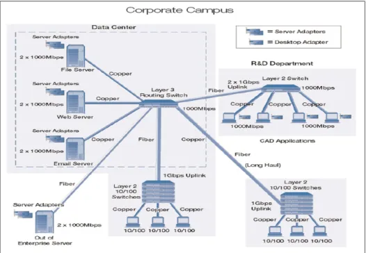
environment, the connectivity between various data centers can range anywhere from tens to hundreds of sites. Most campuses firewall or protect each of the departments individually but usually share a backbone transport network that interconnects all sites to provide uniform network connectivity.
Large enterprise networks mimic some aspects of campus networks. However, enterprise net-works are usually more controlled in terms of allowing connectivity and access to unqualified and unauthorized software. From a topology perspective, a medium to large enterprise would have multiple buildings and departments interconnected by a backbone transport network with each department connected to the core transport network by a router, firewall, Virtual Private Network (VPN). Significant resources and effort are spent to maintain the backbone network to provide resiliency, proper quality of service (QoS), and equal best-effort traffic utilization to departments and groups on campus. RPR can help network managers meet these requirements. RPR provides survivable dual counter-rotating optical rings with several advantages over tra-ditional enterprise network architectures, including support of over-subscription and variable bandwidth per span as well as the provision of advanced traffic routing capabilities. RPR is among the standards the IEEE has defined to enable carrier-class Ethernet.
RPR was standardized by the IEEE 802.17 Working Group in 2004. The primary focus of IEEE 802.17 has been to standardize the media access control (MAC) layer technology for enabling carrier-class RPR over SONET/SDH or Ethernet physical layer transceivers (PHYs). Currently, the IEEE 802.17 Working Group is in the process of standardizing 802.17b, which enhances the RPR bridging methodology for Ethernet packets sourced and/or destined to stations off the ring.
Next-generation metro networks have to bridge the metro gap in order to tap into the vast amount of backbone bandwidth, enable new emerging services, and stimulate revenue growth. To this end, RPR is likely to be attached to large L2 network and we will analyze the man-agement and the performance with this new network including fairness algorithm, STP and Mutlicasting.
Structure of the Thesis
In the following we present the outline of this work to provide an overview of the structure of this thesis.
Chapter 1
Literature review: we introduce the state of the art beginning with optical WDM communica-tions networks, overview of the optical broadband access evolution, metropolitan area packet-switched and ending with the IEEE 802.17 resilient packet ring, SONET/SDH, and GbE; Chapter 2
Objectives of Research and Originality: It describes the objectives of our research and its orig-inality;
Chapter 3
RPR over Ethernet: It describes the conference paper that explains and detail the use of RPR over Ethernet. (2014 IEEE Communication Society – The 5th International conference on Smart Communication in Network Technologies);
Chapter 4
SONET over RPR: It demonstrated that SONET and RPR could be integrated together and it explained and detailed the use of SONET over RPR. (2015 14TH IEEE/ACIS International Conference on computer and Information Science 2015);
Chapter 5
between these two protocols without going through unnecessary conversions. (EDAS Confer-ence and Journal Management System);
Chapter 6
Using RPR, Ethernet, and SONET to create a New Large Layer 2 Network (NLL2N): It demon-strates the possibility of integrating the Resilient Packet Ring (RPR), Ethernet and Synchronous Optical NETwork (SONET) and creating a New Large Layer 2 Networks (NLL2N);
Chapter 7
Results and analysis Chapter 8
Conclusion and recommendations; Chapter 9
This chapter provides a detailed overview of the literature pertaining to optical WDM commu-nications networks, optical networking technologies, metropolitan area packet-switched WDM networks (RingO and Hornet), and Resilient Packet Ring (RPR).
1.1 Optical WDM Communications Networks
1.1.1 Progress and challenges
We are moving toward a society which requires that we have access to information at our fingertips when we need it, where we need it, and in whatever format we need it [Mukher-jee (2000), Ahmed and Shami (2012)]. The information is provided to us through a global mesh of communications networks whose current implementations, e.g., today’s Internet and asynchronous transfer mode (ATM) networks, do not have the capacity to support the foresee-able bandwidth demands. Fiber-optic technology can be considered the savior for meeting the above-mentioned need because of its unique capabilities: Huge bandwidth (nearly 50 terabits per second (Tb/s)), low signal attenuation (0.2dB/km), low signal distortion, and small space requirement. Our challenge is to turn the promise of fiber optics into reality to meet the in-formation network demands of the next decades. Wavelength-division multiplexing (WDM) is an approach that avoids the huge opto-electronic bandwidth mismatch by requiring that each client’s equipment operates only at electronic rate, but multiple WDM channels from different clients may be multiplexed on the same fiber. With WDM, the huge bandwidth of the optical fiber is divided into several dozens or even hundreds of lower bandwidth wavelength channels, each of which operates at electronically processable speeds. WDM devices are easier to im-plement than single-channel high-speed systems since, generally, all components in a WDM device need to operate only at electronic speed; as result, many WDM devices are available in the marketplace today. Research and development on optical WDM networks have
ma-tured considerably over the past few years, and the capacity of deployed systems has grown exponentially, as evidenced by the large number of publications and products.
1.1.2 What Worked and What Did Not
1.1.2.1 What Worked
Clearly, the two major successes of fiber optic communication have been enterprise data links and service provider transmission links and networks [Ramaswami (2006), Maier et al. (2009)]. Enterprise data links use a variety of protocols (100 Mb/s Ethernet, Gigabit Ethernet, 10 Gi-gabit Ethernet, Fibre channel, etc.) and are widely deployed. The majority of these networks operate over the widely deployed multimode fiber plant found in enterprises. Service provider transmission networks operate over single-mode fiber witch enables higher bandwidth trans-mission rates over longer distances. Today, optical fiber transtrans-mission systems can support a couple of hundred wavelengths using WDM, each operating at up to 40 GB/s, all over a single fiber. Here are few examples of what worked:
• Optical add/drop and reconfigurable optical add/drop multiplexers: An optical add/drop
multiplexer (OADM) is an element that allows one or more wavelengths to be dropped and added while allowing the remaining wavelengths to pass through optically, without under-going optical-electrical-optical (OEO) conversion. Today, a new generation of OADMs, called reconfigurable OADMs (ROADMs), are increasingly deployed which allow any wavelength to be dropped and added without impacting other wavelengths. Typically, ROADMs are deployed in optical ring networks;
• Wavelength cross-connects (WXC) are typically deployed in optical mesh networks. They
switch a wavelength from a given input port to another output port independent of the other wavelengths;
• Tunable lasers address two important problems in WDM networks. They eliminate the
wavelength-specific lasers to address different wavelengths by component suppliers, equipment makers, and the ultimate server provider or end-user customer. In addition, tunable lasers allow connections to be provisioned dynamically on demand without manual intervention, when coupled with ROADMs and WXCs;
• Optical protection: Resilience is an important part of network design. Protection switching
plays a key role in enabling this resiliency. The goal of protection switching is to detect failures and reroute traffic around these failures as quickly as possible, typically ranging from within tens of milliseconds to several seconds.
1.1.2.2 What Did not work
Fiber to the home (FTTH) has been talked about since the mid-1990s but is starting only now to materialize. Many factors have impacted this delayed deployment. One was the huge capital investment required to build out the fiber plant. Another was the lack of end-user bandwidth demand. A third factor was the lack of competitive pressure on the telephone companies. A final factor was the effect of telecom regulation requiring the incumbent local exchange providers to unbundle their local plant. Here are few examples for what did not work:
• WDM broadcast-and-select local area networks (LANs) remained prototypes for two
rea-sons: high cost and their inability to provide fast packet switching. Even today we are ex-tremely challenged to accomplish stable sub-microsecond switching between wavelengths and get to practical cost points compared to other technologies such as Ethernet;
• Optical packet switching (OPS): Major impediments still exist to make optical packet
switching (OPS) a reality. Large optical switches that can switch in microseconds do not exist, and the smaller ones that can suffer from high loss and polarization dependence are expensive to fabricate;
• Optical burst switching (OBS) is a technique that falls between optical packet switching
of as rather long packets with durations of, say, milliseconds to even seconds. OBS is per-haps easier to implement than optical packet switching because networks can be designed without optical buffers. However, OBS is significantly more complex to implement than static or dynamic circuit-switched optical networks.
1.2 Overview of The Optical Broadband Access Evolution
The present fast development of new broadband telecommunication services makes the up-grade of the access infrastructure a necessity [Chanclou et al. (2006)]. To run video, voice as well as advanced Internet applications, residential customers require the availability of high-speed solutions. Different solutions for the access network segment have been under devel-opment over the last several years. The most important among these solutions was digital subscriber loop (xDSL). At present, the optical fiber solution is receiving more attention by telecommunication operators than in the past.
Two alternative solutions exist to introduce optical fiber in the access loop: point-to-point (PtP) and point-to-multipoint (PtMP) systems. The first alternative, the PtP system, uses a media converter (MC) to achieve an optical fiber connection with dedicated fiber running from the central office to each end-user. The MC access system supports Ethernet access. PtP is a very flexible solution for an operator and it can be managed remotely because the equipment in the network (Ethernet switch) is intelligent. The second alternative, the PtMP system, typically uses a Passive Optical Network (PON) with a tree topology and passive optical splitter. PONs have several advantages over other access network architectures. One approach for realizing next-generation optical access networks is the use of WDM. It can be used to superimpose several single-wavelengths TDMA PONs over the access fiber line. This approach enables to multiply the capacity of the PONs without requiring a costly upgrade of the existing fiber infrastructure since only the end devices need to be upgraded to support WDM.
1.3 Metropolitan Area Packet-Switched WDM Networks
From the optical networking perspective, the future Internet may be viewed as a three-level hierarchy consisting of backbone networks, metropolitan area networks, and access networks. The backbone will provide abundant bandwidth by employing WDM links that are intercon-nected with reconfigurable optical add-drop multiplexers (ROADMs) and reconfigurable op-tical cross-connects (ROXCs). Metropolitan area networks (MANs) interconnect the back-bone networks with the access networks. The access networks carry the data from and to the individual users. Most existing metro networks are based on synchronous optical net-work/synchronous digital hierarchy (SONET/SDH) technology, a circuit-switched networking technology. In SONET/SDH, circuits (connections operating at fixed data rates) are estab-lished between pairs of network nodes at data rates usually ranging from 155 Mbit/s to 2.5 Gbit/s (OC-3 to OC-48). The circuits are established by the source node and dropped at the destination node using electronic add-drop multiplexers (ADMs). SONET/SDH based metro networks suffer from a number of shortcomings:
• Capacity scaling limitations: upgrading the network capacity to adapt to traffic growth
normally requires expensive ‘forklift upgrades’ where a large fraction of the equipment needs to be replaced which involves high costs and interruption of normal operation;
• Poor bandwidth utilization: bursty, asymmetric IP traffic is handled only inefficiently due
to SONET/SDH’s lack of statistical multiplexing and fast responsiveness;
• High provisioning time: provisioning of additional circuits for new customers usually takes
several weeks to months which are unacceptable in the highly competitive metro market;
• High system complexity: all circuits need to be groomed (multiplexed) into SONET/SDH’s
rigid TDM structure which requires lots of electronic processing and results in high equip-ment cost, inflexibility, and complex operation and maintenance.
In order to address these concerns a number of new WDM metro architectures have been proposed [Herzog et al. (2004)]. In the following, we discuss two WDM ring architectures that received a great deal of attention.
1.3.1 RINGO
The packet-switched RING Optical network (RINGO) [Carena et al. (2004)] has unidirec-tional fiber ring network architecture. It features N nodes, where N also equals the number of wavelengths. Each node is equipped with an array of fixed-tuned transmitters (FTs) and one fixed-tuned receiver (FR) operating on a given wavelength that identifies the node. That is, node j drops wavelength λj from the ring. Thus, in order to communicate with node j, a
given node i has to transmit data by using the laser operating on wavelengthλj, as illustrated
in Figure 1.1.
Figure 1.1 Architecture of the RINGO network Taken from Carena et al. (2004)
All wavelengths are slotted with the slot length equal to the transmission time of a fixed-size data packet plus guard time. Each node performs λ-monitoring, i.e., it checks the state of
the wavelength whether it is busy or idle, on a slot-by-slot basis to avoid channel collisions. This approach is a multichannel generalization of the empty-slot approach. In the empty-slot approach, one bit at the beginning of each slot indicates the state of the corresponding slot, i.e., whether the slot is free (empty) or occupied. A monitoring node is allowed to use only empty slots for its transmissions.
Figure 1.2 depicts the RINGO node structure in greater detail. At each node all wavelengths are demultiplexed. The drop wavelength is routed to a burst-mode receiver while the status of the remaining wavelengths is monitored by using 90/10 taps and an array of photodiodes. The burst-mode receiver recovers the clock for each optical packet very quickly and does not need to receive a continuous signal. The 90/10 taps splits 10% of the optical power from the fiber. Subsequently, the wavelengths are multiplexed on to the outgoing ring fiber. By using a 50/
50 combiner and an external modulator, the node is able to send data packets by activating one or more fixed-tuned transmitters. The50/50 combiner collects signals from two input ports and equally combines them onto one output port. Both input signals experience thereby a combining loss of 3 dB.
1.3.2 HORNET
The Hybrid Optoelectronic Ring NETwork (HORNET) is a unidirectional WDM ring net-work [White et al. (2003)]. All wavelengths are slotted with the slot length equal to the trans-mission time of a fixed-size packet (plus guard time). Each wavelength is shared by several nodes for data reception. Every node is equipped with one fast tunable transmitter and one fixed-tuned burst-mode receiver. As shown in Figure 1.3, the node structure consists of a slot manager, a smart drop, and a smart add module.
Access to all wavelengths is governed by means of a carrier sense multiple access with colli-sion avoidance (CSMA/CA) medium access control (MAC) protocol. When a node transmits a packet it multiplexes a sub-carrier tone onto the packet at a sub-carrier frequency that corre-sponds to the wavelength on which the packet is sent. The destination address of the packet
Figure 1.2 Structure of RINGO node Taken from Carena et al. (2004)
Figure 1.3 HORNET node structure Taken from White et al. (2003)
is modulated onto the sub-carrier multiplexing (SCM) tone using a combination of amplitude shift keying (ASK) and frequency shift keying (FSK). For carrier sensing, the slot manager taps off a small amount of optical power and detects it with one photodiode. The payload data from all wavelengths collide at baseband while the SCM tones remain intact. The composite SCM signal is demultiplexed into the individual SCM tones using a collection of bandpass filters. The SCM tone corresponding to the drop wavelength of the node is FSK demodulated while
the other SCM tones are ASK demodulated. The outcome of the ASK demodulation indicates the absence or presence of a packet on the corresponding wavelength. This allows the node to determine whether a wavelength is free for a packet transmission, which is conducted with the smart add module. The outcome of the FSK demodulation indicates whether there is a packet on the node’s drop wavelength. If there is a packet, it is taken off the ring with the node’s burst-mode receiver. The outcome of the FSK demodulation also gives the destination address of the packet. If the destination address does not match the node’s address, then the node forwards the packet using its smart add module.
1.4 IEEE 802.17 Resilient Packet Ring (RPR) [Daviket al. (2004)]
1.4.1 Fundamentals of RPR
Resilient Packet Ring (RPR), which was standardized in 2004 as IEEE 802.17 RPR, is based on two counter-rotating fiber rings that carry data and control information [Davik et al. (2004), IEE (2004), Spadaro et al. (2004)]. Packet ring-based data networks were pioneered by the Cambridge Ring [Needham and Herbert (1982)], and followed by other important network ar-chitectures. Rings are built using several point-to-point connections. When the connections between the stations are bidirectional, rings allow for resilience (a frame can reach its destina-tion even in the presence of a link failure). A ring is also simpler to operate and administrate than a complex mesh or an irregular network. Networks deployed by service providers in MANs or wide area networks (WANs) are often based on SONET/ SDH rings. Many SONET rings consist of a dual-ring configuration in which one of the rings is used as the backup ring, and remains unused during normal operation, utilized only in the case of failure of the primary ring. The static bandwidth allocation and network monitoring requirements increase the total cost of a SONET network. While Gigabit Ethernet does not require static allocation and pro-vides cost advantages, it cannot provide desired features such as fairness and auto-restoration. Since RPR is being standardized in the IEEE 802 LAN/MAN families of network protocols, it can inherently bridge to other IEEE 802 networks and mimic a broadcast medium. RPR
implements a MAC protocol for access to the shared ring communication medium that has a client interface similar to that of Ethernet’s.
Furthermore, RPR uses the available ring bandwidth more efficiently than SONET/SDH by making use of destination stripping and shortest path routing both enabling spatial bandwidth reuse. With destination stripping, a packet sent along the ring from source node A to destina-tion node B is removed from the ring by node B. The transmission of the packet only consumes bandwidth on the ring segment between node A and B as opposed to legacy ring systems that use source stripping where after passing its destination B the packet continues its travel around the ring until it reaches the source node A. Destination stripping has the advantage over source stripping that bandwidth is only consumed on the ring links between A and B so that other simultaneous transmissions can take place on the remaining links. In other words, destination stripping enables spatial reuse of the ring bandwidth by transmitting multiple packets simulta-neously on different ring segments. For uniform traffic destination stripping doubles the ring capacity compared to source stripping. The spatial reuse of the ring bandwidth is further in-creased by making use of shortest path routing. Since RPR is based on a bi-directional fiber ring a source node can choose the ring direction with the smallest hop distance to the des-tination node. Shortest path routing further reduces the average number of links used for a transmission between two nodes enabling even larger spatial reuse. For uniform traffic, short-est path routing doubles the capacity of a dshort-estination stripping ring compared to sending each packet randomly in either or all packets in the same direction. Figure 1.4 shows an example scenario where spatial reuse is obtained on the outer RPR fiber ring, whereby station 2 trans-mits to station 4 at the same time as station 6 transtrans-mits to station 9. Every station on the ring has a buffer, called transit queue (see Figure 1.4), in which frames transiting the station may be temporarily queued. Each station acts according to two basic rules. The first rule is that the station may only start to add a packet if the transit queue is empty and there are no frames in transit. Second, if a transiting frame arrives after the station has started to add a frame, this transiting frame is temporarily stored (for as long as it takes to send the added frame) in the transit queue. Obviously, these two simple principles need some improvement to make up a
full working protocol that distributes bandwidth fairly. How this is achieved in RPR will be revealed in the next sections.
Figure 1.4 RPR network: a) destination stripping and spatial reuse; b) station’s attachment to only one ringlet,
showing the transit queue Taken from Davik et al. (2004)
1.4.2 Station design and packet priority
The stations on the RPR ring implement a MAC protocol that controls the stations’ access to the ring communication medium. Several physical layer interfaces (reconciliation sub-layers) for Ethernet (called PacketPHYs) and SONET/SDH are defined. The MAC entity also implements
access points which clients can call in order to send and receive frames and status information. RPR provides a three-level class-based traffic priority scheme. The objectives of the class based scheme are to let class A be a low-latency low-jitter class, class B be a class with predictable latency and jitter, and class C be a best effort transport class. It is worthwhile to note that the RPR ring does not discard frames to resolve congestion. Hence, when a frame has been added onto the ring, even if it is a class C frame, it will eventually arrive at its destination. Class A traffic is divided into classes A0 and A1, and class B traffic is divided into classes B-CIR (committed information rate) and B-EIR (excess information rate). The two traffic classes C and B-EIR are called fairness eligible (FE), because such traffic is controlled by the fairness algorithm described in the next section. In order to fulfill the service guarantees for class A0, A1, and B-CIR traffic, bandwidth needed for these traffic classes is pre-allocated. Bandwidth pre-allocated for class A0 traffic is called reserved and can only be utilized by the station holding the reservation. Bandwidth pre-allocated for class A1 and B-CIR traffic is called reclaimable. Reserved bandwidth not in use is wasted. Bandwidth not pre-allocated and reclaimable bandwidth not in use may be used to send FE traffic.
A station’s reservation of class A0 bandwidth is broadcast on the ring using topology messages (topology discovery is discussed later). Having received such topology messages from all other stations on the ring, every station calculates how much bandwidth to reserve for class A0 traffic. The remaining bandwidth, called unreserved rate, can be used for all other traffic classes. An RPR station implements several traffic shapers (for each ringlet) that limit and smooth add and transit traffic. There is one shaper for each of A0, A1, and B-CIR as well as one for FE traffic. There is also a shaper for all transmit traffic other than class A0 traffic, called the downstream shaper. The downstream shaper ensures that the total transmit traffic from a station, other than class A0 traffic, does not exceed the unreserved rate. The other shapers are used to limit the station’s add traffic for the respective traffic classes. The shapers for classes A0, A1, and B-CIR are preconfigured; the downstream shaper is set to the unreserved rate, while the FE shaper is dynamically adjusted by the fairness algorithm. While a transit queue of one maximum transmission unit (MTU) is enough for buffering of frames in transit when
the station adds a new frame into the ring, some flexibility for scheduling of frames from the add and transit paths can be obtained by increasing the size of the transit queue. For example, a station may add a frame even if the transit queue is not completely empty.
Also, a larger queue may store lower-priority transit frames while the station is adding high priority frames. The transit queue could have been specified as a priority queue, where frames with the highest priority are dispatched first. A simpler solution, adopted by RPR, is to op-tionally have two transit queues. Then high-priority transit frames (class A) are queued in the primary transit queue (PTQ), while class B and C frames are queued in the secondary tran-sit queue (STQ). Forwarding from the PTQ has priority over the STQ and most types of add traffic. Hence, a class A frame traveling the ring will usually experience not much more than the propagation delay and some occasional transit delays waiting for outgoing packets to com-pletely leave the station (RPR does not support preemption of packets). Figure 1.5 shows one ring interface with three add queues and two transit queues. The numbers in the circles indicate a crude priority on the transmit link. An RPR ring may consist of both one- and two-transit-queue stations. The rules for adding and scheduling traffic are local to the station, and the fairness algorithm described below works for both station designs.
1.4.3 MAC protocol
1.4.3.1 Ring access
RPR nodes operate in one of two modes: (i) single-queue mode or (ii) dual-queue mode. In single-queue mode, the transit path consists only of the PTQ. If the PTQ is not full, highest priority is given to the local control traffic. At the absence of local control traffic, priority is given to in-transit ring traffic over station traffic. In dual-queue mode, the transit path comprises both PTQ and STQ. The PTQ is used exclusively for class A traffic while the STQ stores packets belonging to class B and C traffic. In dual-queue mode, if both PTQ and STQ are not full, highest priority is given to local control traffic (similar to single-queue mode). If there is no local control traffic, PTQ traffic is served always first. If the PTQ is empty, the local
Figure 1.5 The attachment to one ring by a dual-transit-queue station. The numbers in the circles give a very crude indication of
transmit link priority Taken from Davik et al. (2004)
transmission queue (stage queue) is served until STQ reaches a certain queue threshold. When the STQ reaches that threshold, STQ in-transit ring traffic is given priority over station traffic such that in-transit packets are not lost due to buffer overflow. Thus, the transit path is lossless and a packet put on the ring is not dropped at downstream nodes.
Rings are the dominant topology in metropolitan networks primarily for their protection prop-erties which are discussed in more detail in Section 1.4.3.3; that is, even under a single link or node failure, full connectivity among all ring nodes is maintained. Moreover, rings have re-duced deployment costs from those of star or mesh topologies as ring nodes are only connected to their two nearest neighbors vs. to a centralized point (star) or multiple points (mesh) [Yuan
et al. (2004), Assi et al. (2002)]. Unfortunately, current technology choices for high-speed
metropolitan rings provide a number of unsatisfactory alternatives. Legacy SONET/SDH ring networks allocate bandwidth statically between source-destination node pairs. Internet traffic however is bursty and the connections (circuits) between the individual nodes must be provi-sioned for the traffic peak rate in average resulting in under utilization of the available
band-width. To use the bandwidth more efficiently, next generation metro networks should support statistical multiplexing where the bandwidth is dynamically shared between the nodes. In ad-dition to that, in a SONET-based ring network, a source node must generate a separate copy for each destination for the delivery of multicast/broadcast traffic, and almost half of the en-tire bandwidth is used for the management of the ring. However, the use of circuits prevents unused bandwidth from being reclaimed by other flows and results in low utilization under bursty traffic. On the other hand, a Gigabit Ethernet (GigE) ring can provide full statistical multiplexing, but suffers from poor utilization and unfairness. Low utilization arises because the Ethernet spanning tree protocol requires that one link be disabled to preclude loops, thereby preventing traffic from being forwarded along the true shortest path to the destination. Unfair-ness occurs in GigE, for example, in which nodes will obtain different throughputs to the hub node depending on their spatial location on the ring and input traffic patterns. Finally, legacy ring technologies such as fiber distributed data interface (FDDI) do not employ spatial reuse. That is, by using a rotating token that a node must hold to transmit, only one node can transmit at any given time.
1.4.3.2 Fairness control
In the basic buffer insertion access method, a station may only send a frame if the transit queue is empty. Thus, it is very easy for a downstream station to be starved by upstream ones. In RPR, the solution to the starvation problem is to force all stations to behave according to a specified fairness algorithm. The objective of the fairness algorithm is to distribute unallocated and unused reclaimable bandwidth fairly among the contending stations and use this bandwidth to send class B-EIR and class C (FE) traffic. When defining fair distribution of bandwidth, RPR enforces the principle that when the demand for bandwidth on a link is greater than the supply, the available bandwidth should be fairly distributed between the contending sender stations. A weight is assigned to each station, so a fair distribution of bandwidth need not be an equal one. When the bandwidth on the transmit link of a station is exhausted, the link and station are said to be congested, and the fairness algorithm starts working. The definition of congestion is
different for single- and dual-queue stations, but both types of stations are congested if the total transmits traffic is above certain thresholds. In addition, a single-queue station is congested if frames that are to be added have to wait a long time before they are forwarded, and a dual-queue station is congested if the STQ is filling up (and hence transit frames have to wait a long time before they are forwarded). The most probable cause of congestion is the station itself and its immediate upstream neighbors. So, by sending a so-called fairness message upstream (on the opposite ring), the probable cause of the congestion is reached faster than by sending the fairness message downstream over the congested link. Figure 1.6 shows how the attachment to one ring asks the other attachment to queue and send a fairness message. In the following we focus on fairness on one ring.
Figure 1.6 When a station becomes congested it sends a fairness message upstream
Taken from Davik et al. (2004)
The fairness algorithm on the other ring works exactly the same way. When a station becomes congested it calculates a first approximation to the fair rate by either dividing the available bandwidth between all upstream stations that are currently sending frames through this station, or using its own current add rate. This calculated value is sent upstream to all stations that are
contributing to the congestion, and these stations must adjust their sending rate of FE traffic accordingly. The recipients of this message together with the originating station constitute a congestion domain. There are two options specified for the fairness algorithm. In the conser-vative mode the congested station waits to send a new fair rate value until all stations in the congestion domain have adjusted to the fair rate, and this change is observed by the congested station itself. The estimate of the time to wait (called the Fairness Round-Trip Time, FRTT) is calculated by sending special control frames across the congestion domain. The new fair rate may be smaller or larger than the previous one, depending on the observed change. In the aggressive mode, the congested station continuously (fairness packets are sent with a default interval of 100μs) distributes a new approximation to the fair rate. When the station finally be-comes uncongested, it sends a fairness message indicating no congestion. A station receiving a fairness message indicating no congestion will gradually increase its add traffic (assuming the station’s demand is greater than what it is currently adding). In this way (if the traffic load is stable) the same station will become congested again after a while, but this time the estimated fair rate will be closer to the real fair rate, and hence the upstream stations in the congestion domain do not have to decrease their traffic rate as much as previously.
1.4.3.3 Resilience
RPR is designed with a protection mechanism aiming at restoring traffic within 50 ms in case of a link or station failure [Kvalbein and Gjessing (2005)]. Every station on the ring is reachable through either one of the ringlets, which allows one ringlet to serve as a secondary path for traffic of the other. Each station maintains a topology image, with information on the hop count to the other stations on both ringlets. The operation of the RPR protection mechanism is transparent to higher layer protocols like IP, except for the performance degradation that will be experienced following a failure. RPR has two protection mechanisms, wrapping and steering. With wrapping, packets arriving at point of failure are wrapped over to the other ringlet, and follow this ringlet to the destination. Wrapping gives a very short response time to a failure, and minimizes packet loss. The focus of this work is on the steering protection
mechanism. With steering, when a failure occurs between the source and the receiver, the source station moves traffic over from the normal primary ringlet, to the ringlet on which the receiver can still be reached, termed the secondary ringlet, as shown in Figure 1.7. This protection mechanism, called steering, might introduce packet reordering, if packets traversing the new path experience a shorter buffering delay in the transit nodes than the packets in transit along the old path. Hence, a mechanism is needed in order to guarantee that no packets sent before the failure occurred will arrive at the destination after packets start arriving from the new ringlet.
Figure 1.7 RPR network with source S, receiver R, and a link failure B Taken from Kvalbein and Gjessing (2005)
1.4.4 Strengths and weaknesses of RPR
RPR technology has attracted considerable interest in the last years. Important issues related to the use of RPR technology are discussed in the following, to point out its advantages and review its disadvantages.
The protection mechanisms implemented in RPR are fast, they aim to achieve recovery times of approximately 50 ms and to protect against any single failure in the ring. No bandwidth is
dedicated for recovery purposes; therefore, in a failure-less state resource utilization is high. However, in failure, the bandwidth available is substantially reduced. The reduction factor depends on the actual load and distribution of traffic.
If high-priority traffic is used in an RPR ring, the traffic must be shaped at ingress, and the service that uses this type of traffic must be carefully engineered. No mechanisms are provided to solve contention among high-priority traffic streams. If the high-priority traffic admitted exceeds the capacity of a given span, low-priority traffic is blocked. Thus, if problems are to be avoided, the amount of high-priority traffic injected into the ring must be controlled and limited by higher layers, especially in the case of failure. We suggest that each failure scenario be investigated in turn to determine whether a given load is handled properly.
RPR would seem to be a wise choice for efficient and reliable transport of best effort traffic. It may be used to transport traffic with strict bandwidth and delay requirements, although in this case one would need to verify whether RPR would satisfy the necessary parameters for all conceivable traffic flow patterns. With regard to the use of different classes of traffic, RPR requires external measures to prevent congestion. These measures are not standardized or otherwise defined at present, so it is up to the user to provide them. However, it is possible that such measures will be defined as RPR technology matures and its use becomes widespread. An important issue in modern telecommunications networks is interoperability among different layers. A new protocol should interwork smoothly with existing protocols. Interoperability with several physical layer techniques was explicitly considered during the standardization process of the IEEE 802.17 RPR. From the upper layer point of view RPR may be seen as a shared medium technology, and as such the problem was not widely studied
1.5 Synchronous Optical NEtwork (SONET) [IEC]
1.5.1 Introduction to SONET
Synchronous Optical NETwork (SONET) and Synchronous Digital Hierarchy (SDH) are equiv-alent standards with minor differences. SONET is used widely in North American, and SDH is used in Europe and the rest of the world. For the purpose of this dissertation only SONET ter-minology is used and discussed. The overhead insertion mechanism, however, can be applied to both.
SONET was originally developed for the telephone network as a long-term solution for a mid-span-meet between vendors. The standard was proposed by Bellcore and was established in 1984. SONET defines the rates and formats, the physical layer, network element architectural features, and network operational criteria for a fiber optic network. The standard soon becomes an excellent way for data communication as well, because it fits well in the physical layer of the OSI data network model.
1.5.2 Rates and formats
1.5.2.1 Typical End-to-End Connection
Because many existing networks use communication schemes of different digital signal hier-archies, encoding techniques, and multiplexing strategies, the complexity and cost to inter-connect these networks are high. To reduce this complexity and cost, SONET was defined to standardized rates and formats for interoperability.
SONET systems are synchronous because all system elements use similar clocks rated at a grade of Stratum 3 or higher. The Optical carrier (OC) level and the electrical equivalent, Syn-chronous Transport Signal (STS), are the building blocks used in SONET. A STS consists of two parts: the STS payload and the STS overhead. The STS payload carries the communicated information, while the STS overhead carries signaling and protocol information.
For two user networks to communicate, the signals are converted to a STS, carried through various SONET networks before the SONET terminating equipment converts the STS back to the user network format. As illustrated in Figure 1.8, four layers exist for the typical SONET end-to-end connection: the path layer, line layer, section layer and photonic layer.
Figure 1.8 SONET Layers Taken from Prakash
Information from each layer is communicated to and processed by the same layer in the ter-minating equipment and this processed information is passed up and down the layers. Each layer is responsible for specified aspects of the physical interface. The path is responsible for monitoring; the line is responsible for synchronization, multiplexing, and protection switching; the section, for framing, scrambling, and error monitoring; and the photonic layer, for setting the pulse shape, power level, and wavelength.
1.5.3 Frame Structure
The basic SONET frame is as shown in Figure 1.9. This signal is known as Synchronous Transport Signal Level-1 (STS-1). It consists of 9 rows of 90 bytes i.e., a total of 810 bytes. It is transmitted from left to right and top to bottom. The two dimensional figure is just for convenience. Actual transmission takes place serially, i.e., the left most byte in the top row is transmitted, then the second byte in the first row and so on. After the 90th byte in the first row the left most byte in the second row is transmitted and it goes on. One more point to be noted is that msb is transmitted first and the numbering of bits in a byte is as shown in Figure 1.10. The
frame length is 125μs (i.e., 8000 frames per second). The STS-1 has a bit rate of 51.84 Mbps. The frame for the lowest SDH rate STM-1 contains 270 columns by 9 rows. We will learn more about it later.
Figure 1.9 SONET Frame Taken from Prakash
The first 3 columns of SONET frame are called Transport Overhead (TOH). The remaining 87 columns are called Synchronous Payload Envelope (SPE). The first column of SPE is called Payload Overhead (POH). A point to be noted here is that every SONET frame repeats every 125μs no matter how fast the line speed gets. As line rate goes up SONET frame gets bigger, just sufficient to keep the frame rate at 8000 frames per second.
1.5.4 Overheads
SONET provides substantial overhead information, allowing simpler multiplexing and greatly expanded OAM&P (Operations, Administration, Maintenance, and Provisioning) capabilities. The overhead information has several layers, which are shown in Figure 1.10. Path-level
over-head is carried from end-to-end; it’s added to DS1 signals when they are mapped into virtual tributaries and for STS-1 payloads that travel end-to-end.
Line overhead is for the STS-N signal between STS-N multiplexers. Section overhead is used for communications between adjacent network elements, such as regenerators.
Enough information is contained in the overhead to allow the network to operate and allow OAM&P communications between an intelligent network controller and the individual nodes. The following sections detail the different SONET overhead information:
• Section Overhead; • Line Overhead; • STS Path Overhead; • VT Path Overhead.
Figure 1.10 Overhead layers Taken from IEC
1.5.5 SONET Multiplexing
The multiplexing principles of SONET are: Mapping
A process used when tributaries are adapted into Virtual Tributaries (VTs) by adding justifica-tion bits and Path Overhead (POH) informajustifica-tion;
Aligning
This process takes place when a pointer is included in the STS Path or VT Path Overhead, to allow the first byte of the Virtual Tributary to be located;
Multiplexing
This process is used when multiple lower-order path- layer signals are adapted into a higher-order path signal, or when the higher-higher-order path signals are adapted into the Line Overhead; Stuffing
SONET has the ability to handle various input tributary rates from asynchronous signals. As the tributary signals are multiplexed and aligned, some spare capacity has been designed into the SONET frame to provide enough space for all these various tributary rates. One of the benefits of SONET is that it can carry large payloads (above 50 Mb/s).
To achieve this capability, the STS Synchronous Payload Envelope can be sub-divided into smaller components or structures, known as Virtual Tributaries (VTs), for the purpose of trans-porting and switching payloads smaller than the STS-1 rate. All services below DS3 rate are transported in the VT structure.
Figure 1.11 illustrates the basic multiplexing structure of SONET. Any type of service, ranging from voice to high-speed data and video, can be accepted by various types of service adapters. New services and signals can be transported by adding new service adapters at the edge of the SONET network. Except for concatenated signals, all inputs are eventually converted to a base format of a synchronous STS-1 signal (51.84 Mb/s or higher). Lower speed inputs such as DS1s are first bit- or byte-multiplexed into virtual tributaries. Several synchronous STS-1s are
then multiplexed together in either a single- or two-stage process to form an electrical STS-N signal (N = 1 or more). STS multiplexing is performed at the Byte Interleave Synchronous Multiplexer. Basically, the bytes are interleaved together in a format such that the low-speed signals are visible. No additional signal processing occurs except a direct conversion from electrical to optical to form an OC-N signal.
Figure 1.11 SONET multiplexing hierarchy Taken from IEC
1.5.6 Ring Architecture
The SONET building block for ring architecture is the ADM. Multiple ADMs can be put into a ring configuration for either bi-directional or uni-directional traffic (see Figure 1.12). The main advantage of the ring topology is its survivability; if a fiber cable is cut, the multiplexers have the intelligence to send the services affected via an alternate path through the ring without interruption. The demand for survivable services, diverse routing of fiber facilities, flexibility to rearrange services to alternate serving nodes, as well as automatic restoration within seconds, have made rings a popular SONET topology.
Figure 1.12 Ring architecture Taken from IEC
1.6 Gigabyte Ethernet (GE) [CIS, Chittiet al. (2015)]
1.6.1 Introduction
Invented by Dr. Robert Metcalf and pioneered by Intel, Digital and Xerox, Ethernet has be-come the most commonly used LAN technology worldwide. More than 85% of all installed network connections are Ethernet, according to International Data Corporation (IDC, 2000). As a transport protocol, Ethernet operates at Layers 1 and 2 of the 7-layer OSI networking model, delivering its data packets to any device connected to the network cable. IT managers have found that Ethernet is simple, easy to use and readily upgradeable. An organization can scale from 10 to 100 or 1000 Mbps Ethernet, either network-wide or a segment at a time, knowing that the new equipment will be backwards compatible with legacy equipment. This reduces the infrastructure investment that an organization must make. Ethernet is also a reli-able technology. Experience shows that it can be deployed with confidence for mission-critical applications.
1.6.2 Standards Evolution
In the last several years, the demand on the network has increased drastically. The old 10BASE5 and 10BASE2 Ethernet networks were replaced by 10BASE-T hubs, allowing for greater man-ageability of the network and the cable plant. As applications increased the demand on the network, newer, high-speed protocols such as FDDI and ATM became available. However, Fast Ethernet became the backbone of choice because its simplicity and its reliance on Ether-net. The primary goal of Gigabit Ethernet was to build on that topology and knowledge base in order to build a higher-speed protocol without forcing customers to throw away existing net-working equipment. The standards body that worked on Gigabit Ethernet was the IEEE 803.2z Task Force. The possibility of a Gigabit Ethernet Standard was raised in mid-1995 after the final ratification of the Fast Ethernet Standard. By November 1995 there was enough interest to form a high-speed study group. This group met at the end of 1995 and several times during early 1996 to study the feasibility of Gigabit Ethernet.
The meetings grew in attendance, reaching 150 to 200 individuals. Numerous technical con-tributions were offered and evaluated. In July 1996, the 802.3z Task Force was established with the charter to develop a standard for Gigabit Ethernet. Basic concept agreement on tech-nical contributions for the standard was achieved at the November 1996 IEEE meeting. The first draft of the standard was produced and reviewed in January 1997; the final standard was approved in June 1998.
1.6.3 Gigabit Ethernet Protocol Architecture
In order to accelerate speeds from 100 Mbps Fast Ethernet up to 1 Gbps, several changes need to be made to the physical interface. It has been decided that Gigabit Ethernet will look identical to Ethernet from the data link layer upward. The challenges involved in accelerating to 1 Gbps have been resolved by merging two technologies together: IEEE 802.3 Ethernet and ANSI X3T11 Fibre Channel. Figure 1.13 shows how key components from each technology have been leveraged to form Gigabit Ethernet.
Figure 1.13 Gigabit Ethernet Protocol Stack Taken from CIS
Leveraging these two technologies means that the standard can take advantage of the exist-ing high-speed physical interface technology of Fibre Channel while maintainexist-ing the IEEE 802.3 Ethernet frame format, backward compatibility for installed media, and use of full- or half-duplex carrier sense multiple access collision detect (CSMA/CD). This scenario helps minimize the technology complexity, resulting in a stable technology that can be quickly de-veloped. The actual model of Gigabit Ethernet is shown in Figure 1.14. Each of the layers will be discussed in detail.
1.6.4 Physical Interface
Figure 1.14 Architectural Model of IEEE 802.3z Gigabit Ethernet Taken from CIS
Figure 1.15 802.3z and 802.3ab Physical Layers Taken from CIS
1.6.5 Media Access Control Layer
Gigabit Ethernet has been designed to adhere to the standard Ethernet frame format. This setup maintains compatibility with the installed base of Ethernet and Fast Ethernet products, requiring no frame translation. Figure 1.16 describes the IEEE 802.3 Ethernet frame format.