Numerical modeling for determining the local vertical hydraulic gradient
at the wall of a tunnel
Alireza Shahbazi, Ali Saeidi, & Romain Chesnaux
Department of applied science – University of Quebec at Chicoutimi, Chicoutimi, Quebec, Canada
ABSTRACT
The determination of the flow rate in the underground excavation is a very important parameter in the design of the structures. Among all parameters that have an impact on the inflow rate to the tunnel, the hydraulic gradient is one of the most effective one that, according to Darcy’s law, controls the tunnel inflow rate. An empirical-numerical equation is proposed for the determination of the vertical hydraulic gradient in the wall of a tunnel excavated below a water table. The horizontal hydraulic gradient is not supposed to have a significant impact on the tunnel inflow rate as its value is very low. By contrast, the existing vertical hydraulic gradient is among the most effective parameters. On the other hand, in the case of an underground excavation, no equation exists for the determination of the hydraulic gradient that considers more than one parameter, i.e., the depth. Using the results of the numerical simulations, it was deduced that the depth of the tunnel, the ratio between principal hydraulic conductivities, and their relevant directions are the most effective parameters that have a significant influence on the hydraulic gradient and inflow rate to the underground tunnels. The resultant hydraulic gradients in the vicinity of the wall of the tunnel were obtained using the RS2 Rocscience software. The mathematical relationship between the input data, i.e., the depth (z), ratio between hydraulic gradients (a) and their relevant directions (α), and the result of the simulation, i.e., the hydraulic gradient (iz), have been derived by curve fitting. Finally, for each
orientation of the principal hydraulic conductivity, an equation is proposed for the calculation of the hydraulic gradient. Keywords
Hydraulic gradient, tunnel inflow rate, numerical modeling, hydraulic conductivity RÉSUMÉ
La détermination du débit dans une excavation souterraine est un paramètre très important dans la conception des structures. Parmi tous les paramètres qui ont un impact sur le débit d'entrée dans le tunnel, le gradient hydraulique est l'un des plus influents qui, selon la loi de Darcy, contrôle le débit d'entrée du tunnel. Une équation empirico-numérique est proposée pour la détermination du gradient hydraulique vertical dans la paroi d'un tunnel creusé sous une nappe phréatique. Le gradient hydraulique horizontal n'est pas censé avoir un impact significatif sur le débit d'entrée du tunnel, car sa valeur est très faible. En revanche, le gradient hydraulique vertical existant a un impact significatif. En outre, dans le cas d'une excavation souterraine, aucune équation n'existe pour la détermination du gradient hydraulique qui prend en compte plus d'un paramètre, c'est-à-dire la profondeur. En utilisant les résultats des simulations numériques, il a été déduit que la profondeur du tunnel, le rapport entre les principales conductivités hydrauliques et leurs directions pertinentes sont les paramètres les plus efficaces qui ont une influence significative sur le gradient hydraulique et le débit d'entrée dans les tunnels souterrains. Les gradients hydrauliques résultants au voisinage de la paroi du tunnel ont été obtenus à l'aide du logiciel RS2 Rocscience. La relation mathématique entre les données d'entrée, c'est-à-dire la profondeur (z), le rapport entre les gradients hydrauliques (a) et leurs directions pertinentes (α), et le résultat de la simulation, c'est-à-dire le gradient hydraulique (iz), ont été dérivés par ajustement de courbe. Enfin, pour chaque orientation de la conductivité hydraulique
principale, une équation est proposée pour le calcul du gradient hydraulique.
Mots clés: Gradient hydraulique, débit entrant dans le tunnel, modélisation numérique, conductivité hydraulique
1 INTRODUCTION
Prior to excavating a tunnel, the ability to predict the probable inflow rate to the tunnel could effectively help to
first evaluate the stability of the tunnel walls, and second, to evaluate the possible equipment to evacuate seeped water from the excavation area (El Tani 1999, Fernandez and Moon 2010, Borbély 2018). Assessing the inflow rate to the tunnel also makes it possible to anticipate the environmental impacts on water resources and human activities as a result of altering the groundwater regime and
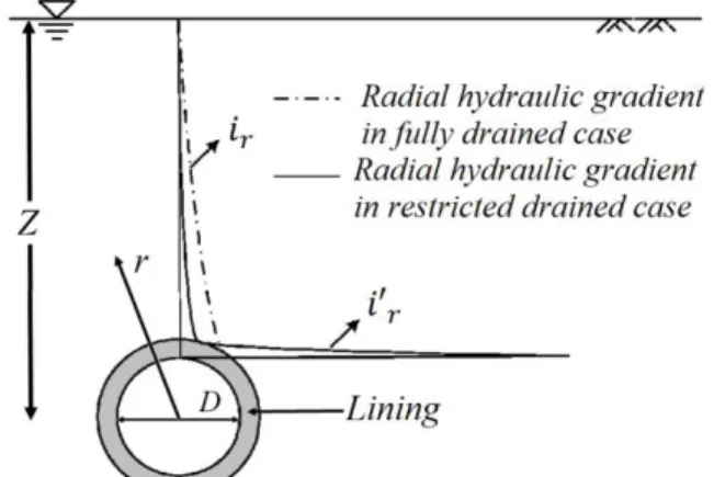
settling the surface structures (Karlsrud 2001). In addition, seepage could produce extra pressure on temporary and permanent support systems in the tunnel, leading to a slowdown of the excavation rate (Farhadian and Katibeh 2017). Several studies were conducted for anticipating the inflow rate to the tunnel, using the analytical models, empirical equations or numerical simulations (Shahbazi, Saeidi et al. 2020). In order to assess the inflow rate to tunnels and based on the Darcy’s law, the hydraulic gradient should be specified as an effective parameter that controls the flow rate and its direction through a formation. Accordingly, in order to determine the inflow rate to the tunnel, the existing hydraulic gradient in the vicinity of the wall of the tunnel must be defined. Determination of the hydraulic gradient at the tunnel wall has rarely been considered by researchers; instead, the water head above the tunnel has been used to calculate the inflow rate. Previous investigations regarding the determination of the hydraulic gradient were mostly conducted with the aim of evaluating the variation of the hydraulic head across the lining-like zone around the tunnel (Fernández 1994, Lee, Nam et al. 2003, Fernandez and Moon 2010). In a research study conducted by Shin et al (Shin, Shin et al. 2009), the variation of the hydraulic gradient in the vertical direction in the presence of a circular tunnel with lining was determined according to Eq. [1] (Fig 1).
Fig 1. The variation of the hydraulic gradient in the vertical direction above the tunnel (Shin, Shin et al. 2009)
𝑖𝑟 𝑍2= 0.0012 ( 𝑟 𝐷) −1.0346 [1]
Where, ir is the radial component of the hydraulic
gradient, Z is the depth of the tunnel center below the groundwater table in meters, D is the diameter of the tunnel (m) and r is the distance from the center of the tunnel (m). Eq. [1] transforms to Eq. [2] that determines the hydraulic gradient at the wall of the tunnel (where r=D/2) as a function of the depth Z of the center of the tunnel below the groundwater table.
𝑖𝑟=𝐷 2⁄ = (2.458 × 10⁻³) 𝑍2
[2]
The relation of dependence between the hydraulic gradient and the depth of the center point of an underground excavation is quite clear, as demonstrated in Eq. [2]. However, it is likely that the hydraulic characteristics of the formation (considered in the model as isotropic and homogeneous) could affect the hydraulic gradient. In this paper, the interdependency between the hydraulic gradient at the wall of the tunnel and various other parameters is numerically investigated and accordingly, a new and more comprehensive equation has been developed. The proposed equation correlates the input data to the numerical model and the resultant hydraulic gradient in the wall of the tunnel by curve fitting method.
2 MODEL DEVELOPMENT
2.1 Parameters selection
A set of numerical simulations using RS2 software (Rocscience 2019) has been performed to assess several parameters: 1) the variation of the vertical hydraulic gradient (iz) with the change of depth (z, the depth below
water table); 2) the ratio between vertical and horizontal hydraulic conductivities (a=Ky/Kx); 3) the directions of the
fractures (α, the angle between Kx and x axis). The
definition of these parameters aims to make the Laplace equation concordant with homogeneous and isotropic conditions. The Laplace equation for homogeneous and anisotropic aquifers in a steady state condition could be written as Eq. [3] (Todd 1980):
𝑘𝑥 𝜕2ℎ 𝜕𝑥2+ 𝑘𝑦 𝜕2ℎ 𝜕𝑦2= 0 [3]
Where h is the hydraulic head and x and y are the coordinate axes. In another form, this equation could be rewritten as Eq. [4] 𝜕2ℎ 𝜕𝑥2+ 1 (𝑘𝑥 𝑘𝑦 ⁄ ) 𝜕2ℎ 𝜕𝑦2= 0 [4]
According to Eq. [4], for anisotropic aquifers, the ratio between hydraulic conductivities could affect the hydraulic head. On the other hand, the orientations of the hydraulic conductivities will affect the (Kx/Ky) ratio, as well. Therefore,
these two parameters, as well as the depth of the tunnel centre below the water table, were used to develop the hydraulic gradient determinant equation.
2.2 Numerical modeling
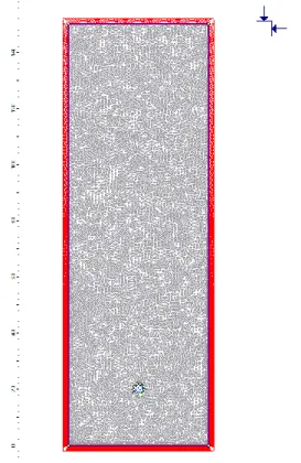
The numerical model consists of a cylindrical tunnel with a radius of 2 m that is excavated in a homogeneous fine sand, whose horizontal hydraulic conductivity (Kx) is 1×10 -6 m/s and without the presence of porosities. The model
dimensions are 50 m×150 m (model width and height, respectively). (Fig 2)
Fig 2. RS2 model for the presence of a tunnel in a homogeneous formation
In the first step, the variations of vertical hydraulic gradient that exist in the wall of the tunnel (iz) with depth (Z)
for different ratios of hydraulic conductivities (a) are calculated for 4 orientations of the hydraulic conductivities (the angle between horizontal hydraulic conductivity and x-axis equal to α=0, 20, 30, 45). In Fig 3, the relevant diagram is presented.
Fig 3. The variation of iz with a in various depths of the
between horizontal hydraulic conductivity and x-axis) a) α=0 b) α=20 c) α=30 and d) α=45.
The dependency of A and B coefficients of Fig 3 to a, is demonstrated in Fig 4.
Fig 4. Variation of the A and B coefficients with a
Based on Fig 3 and Fig 4, the variation of the hydraulic gradient with z, a and α could be empirically represented by Eq. [5].
𝑖𝑧= 𝐴𝑍 + 𝐵 = (𝐶 𝑎𝐷)𝑍 + (𝐸 ln 𝑎 + 𝐹)
[5]
Where the coefficients C, D, G and H for different angles α are given in Table 1.
Table 1. Constants in Eq. [5] given for different values of the angle (α) Angle with x axis (α) C D E F 0 0.1502 -0.371 -0.133 -0.4028 20 0.1508 -0.314 -0.098 -0.3954 30 0.164 -0.271 -0.027 -0.4236 45 0.1636 -0.073 -0.076 -0.4817 3 DISCUSSION
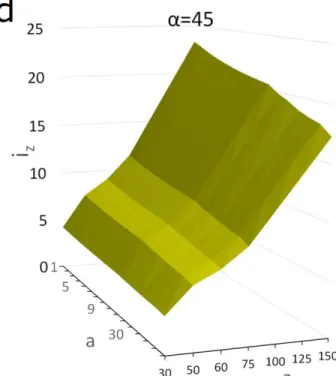
When a tunnel is excavated, the existing hydraulic gradient is modified to a new condition: its direction will be mostly vertical. The projection of the overall hydraulic gradient in the plane of the fracture, on the other hand, will depend on the orientation of the fracture. Furthermore, the overall hydraulic gradient that is produced after excavation of the tunnel depends on the tunnel depth, ratio between hydraulic gradients and their orientations. Fig 3 illustrates that the variation of vertical hydraulic gradient at the wall of the tunnel by depth is linear, and more importantly, it does not depend on the hydraulic conductivity of the formation. This means that the vertical hydraulic gradient at the wall of an underground excavation is the same for the all formations, independently of their hydraulic conductivity. In Fig 5, the variation of iz by Z and a at various α has been
Fig 5. The variation of hydraulic gradient with depth and ratio of hydraulic conductivities at different α (angles between horizontal hydraulic conductivity and x-axis) a) α=0 b) α=20 c) α=30 and d) α=45. The variation of the hydraulic gradient with depth is more sensible to α in figures a, b and c.
According to Fig 5, the hydraulic gradient increases with the increase in depth and the decrease in a. Its variation is more sensitive to depth than to a in a constant α. Deviation of α from the horizontal direction will mostly affect the variation of iz with depth rather than a. The
minimum iz is gained in shallow depths, high value of a and
low value of α, and the maximum iz will be gained in the
opposite conditions. Therefore, the inflow rate is expected to reach its highest value in a homogeneous (minimum a) formation when its hydraulic conductivity is horizontally aligned (α=0). This condition will be satisfied in a rock mass with horizontal and/or vertical joint sets in which a tunnel is excavated horizontally.
Determination of the hydraulic gradient at the wall of an underground excavation is important because according to Darcy’s law, it is not possible to define the inflow rate without knowing this parameter. In previously developed analytical methods, the hydraulic gradient was substituted in the equations by water head above the tunnel (h) that varies only with the variation of depth below water table and does not depend on the anisotropy of the hydraulic conductivity. The geological characteristics of the formation, stress history, depositional environment etc. could have impact on the anisotropy of the hydraulic conductivity. The hydraulic conductivity that is defined by the proposed method is a dependent variable, as well. As a result, it is expected that the estimated inflow rate to the
tunnel by this method may be more reliable than previously developed equations for rock mass formations.
4 CONCLUSION
A numerical equation is developed to calculate the vertical hydraulic gradient in the wall of the tunnel; this value is meant to be inputted into the analytical series of equations that make up the new proposed method. The horizontal hydraulic gradient (ix and iy) is neglected in this model as it
is assumed that the water table is almost horizontal. It is deduced that the vertical hydraulic gradient at the wall of the tunnel (iz), that is the determining factor of the inflow
rate, is dependent on the depth of the tunnel (z), the ratio between principal hydraulic conductivities (a) and their orientation (α). Finally, for each orientation and using curve fitting, an equation is proposed for determination of the iz.
It should be noted that determination of the hydraulic gradient was not a focus of previous research works where models were based on presuming a homogeneous and isotropic formation and solving the Laplace equation.
5 REFERENCES
Borbély, D. (2018). "Tunnel-excavation-induced permeability change of rock mass around a radioactive waste repository tunnel." Central European Geology 61: 73–84.DOI: https://doi.org/10.1556/24.61.2018.05. El Tani, M. (1999). Water inflow into tunnels. Proceedings of the World Tunnel Congress ITA-AITES. Switzerland, International Tunneling and Underground Space Association: 61–70.
Farhadian, H. and H. Katibeh (2017). "New empirical model to evaluate groundwater flow into circular tunnel using multiple regression analysis." International Journal of Mining Science and Technology 27(3): 415-421.DOI: http://dx.doi.org/10.1016/j.ijmst.2017.03.005.
Fernández, G. (1994). "Behavior of pressure tunnels and guidelines for liner design." Journal of geotechnical engineering 120(10): 1768-1791.DOI:
https://doi.org/10.1061/(ASCE)0733-9410(1994)120:10(1768).
Fernandez, G. and J. Moon (2010). "Excavation-induced hydraulic conductivity reduction around a tunnel – Part 1: Guideline for estimate of ground water inflow rate." Tunnelling and Underground Space Technology 25(5): 560-566.DOI:
https://doi.org/10.1016/j.tust.2010.03.006.
Karlsrud, K. (2001). "Control of water leakage when tunneling under urban areas in the Oslo region." NFF Publication 4(12): 27-33.
Lee, I.-M., S.-W. Nam and J.-H. Ahn (2003). "Effect of seepage forces on tunnel face stability." Canadian Geotechnical Journal 40(2): 342-350.DOI: https://doi.org/10.1139/T02-120.
Rocscience (2019). RS2, 2D Geotechnical finite element analysis. Toronto, Canada, Rocscience Inc.
Shahbazi, A., A. Saeidi and R. Chesnaux (2020). "A review of existing methods used to evaluate the hydraulic conductivity of a fractured rock mass." Engineering
Geology 265: 105438.DOI:
https://doi.org/10.1016/j.enggeo.2019.105438. Shin, Y., J. Shin and I. M. Lee (2009). Ground reaction due
to tunnelling below groundwater table. 6th International Symposium on Geotechnical Aspects of Underground Construction in Soft Ground, IS-Shanghai.