Science Arts & Métiers (SAM)
is an open access repository that collects the work of Arts et Métiers Institute of
Technology researchers and makes it freely available over the web where possible.
This is an author-deposited version published in:
https://sam.ensam.eu
Handle ID: .
http://hdl.handle.net/10985/17335
To cite this version :
Jean-Benoit KOPP, Christophe FOND, Gilles HOCHSTETTER - Rapid crack propagation in
PA11: An application to pipe structure Engineering Fracture Mechanics Vol. 202, p.445457
-2018
Any correspondence concerning this service should be sent to the repository
Administrator :
[email protected]
Rapid crack propagation in PA11: An application to pipe structure
Jean-Benoît Kopp
a,⁎, Christophe Fond
b, Gilles Hochstetter
caI2M, Arts et Métiers Paris Tech, Esplanade des Arts et Métiers, F33800 Talence, France bICube, Université de Strasbourg, 2 rue Boussingault, F67000 Strasbourg, France cArkema France, 420 rue d’estienne d’orves, F92700 Colombes, France
Keywords:
Rapid crack propagation Dynamic fracture Energy release rate Polyamide Pipes Finite element Inertial effects
Fracture surface roughness
A B S T R A C T
Dynamic fracture mechanism in Polyamide 11 (PA11) material has been described at laboratory scale to access to an intrinsic material parameter. A liquid transportation application is con-sidered with polymer pipes. A preliminary numerical analysis of the rapid crack propagation (RCP) in polymer pipe isfirstly realised. Two boundary conditions, imposed displacement or pressure, are numerically investigated. The work of external forces is not negligible for pres-surized polymer pipe. A reliable estimate of the dynamic energy release rate GIdis in this last case
not guaranteed. To limit unwanted structural effects a specific experimental device has been used to ensure a permanent regime of RCP in Pre-Stressed Pipe Specimen (PS2). Experimental dynamic fracture tests are realised with Polyamide 11 PS2. Dynamic instabilities inducing“ring-off” and “snake” mechanisms which could appear during full-scale test are not observed with this new test. Afinite element procedure is used to estimate the material toughness GIDof PA11. Knowing
the crack tip location during RCP inertia effects (i.e. kinetic energy) are quantified. The mean crack tip velocity is observed not to change in PA11 whatever the crack configuration (branching or not). This velocity is known to be the crack branching velocity (≈0.6cR). The average dynamic
energy release rate 〈GID〉is equal to 1.5 ± 0.1 kJ m−2at the crack branching velocity. The non-trivial fracture surface roughness is observed with a scanning electron microscope.
1. Introduction
Studying dynamic fracture in a material is not a simple matter. The main question is probably not why the crack is initiated and how much the energy release rate is necessary for that, but what is the minimal energy release rate necessary to ensure rapid crack propagation (RCP) in the material. If it is possible to answer this last question, it is possible to conceive reliable structures in order to avoid storing enough energy in the structure to ensure dynamic fracture. The minimal energy release rate to ensure RCP is generally significantly inferior to the energy release rate necessary to initiate a crack. That is why dynamic fracture happens even if a safety coefficient is considered. If an external accidental impact provides enough energy to initiate the crack, the dynamic crack propagation is possible in pre-stressed structures. Two international Standard test methods (full- and lab-scale) exist to characterize RCP in polymer pipe but it remains according to Leevers imperfectly understood[1]. We totally agree with this comment.
Polymer materials (polyethylene and polyamide especially) often used to manufacture pipes can suffer to RCP[2–11]. This kind of mechanism which is fortunately infrequent in this kind of structure is highlighted by a longitudinal dynamic crack propagation at some hundred meters per second. The external loading, the crack speed and the material micro-structure are known to affect the crack path. For example, in the case offluid-pressurized polymer pipelines, standard tests reveal specific mechanisms such as the
https://doi.org/10.1016/j.engfracmech.2018.08.025
⁎Corresponding author.
E-mail address:[email protected](J.-B. Kopp).
“ring-off” and a sinusoidal crack path called a “snake”[3,11]. These probable kinds of structural effects could influence, such as
viscoplasticity and inertia effects, the dynamic of fracture of polymer materials in a sensitive manner. The estimate of material parameters as the energy release rate or the stress intensity factor is therefore complex [12–14]. These kinds of parameters are necessary to design reliable structures. That is why RCP in materials have been extensively studied for many years especially in mode I and by considering as often as possible the linear elastic fracture mechanics formalism[15–23]. Considering a dynamic regime of propagation in polymer materials the fracture process zone can be often considered confined and therefore negligible comparatively to the crack length. The opening mode (mode I) is commonly studied due to its criticality for materials. In mode I the material needs less energy to maintain crack propagation comparatively to mode II and III.
The use of semi-crystallines and rubber toughened polymers to limit crack initiation and propagation lets appear a specific dynamic fracture behaviour[24,25]. The soft part of the microstructure (i.e. the amorphous part of the semi-crystalline or the elastomeric part in rubber toughened polymers) increases the critical energy release rate to initiate a crack. But this reinforcement is often useless during a high loading rate, for example during a rapid crack propagation. The microstructure reinforcement increases the crack initiation resistance of the material but has no effect on the crack propagation resistance. In the case of rubber toughened polymethylmethacrylate (RT-PMMA), the crack initiation toughness is approximately ten times bigger than that of poly-methylmethacrylate (PMMA). But the crack propagation toughness is quite identical between PMMA and RT-PMMA. In RT-PMMA, the bigger the crack length, the lower the energy release rate. That is why the material can be called (as Schirrer proposed[26]) “hyperbrittle”. At high strain rates elastomeric particles are under the well known glass transition temperature (Tg) and only the
matrix resistance should be considered[26,27,24]. During a quasi-static loading rubber particles have time to cavitate. This is highlighted by the whitening of the material. During a rapid crack propagation this last mechanism is not observable any more[24]. One could considerer RT-PMMA as a model two phased material with a soft and a stiff part. Semicrystallines which have a com-parable microstructure could probably highlight the same transition in damage and fracture mechanisms.
It is more or less recently admitted that the dynamic energy release rateGIDof polymer materials varies with the crack tip velocity
which is in the range of a fraction of Rayleigh wave speed (cR) [26,28]or with the created fracture surface area [24,25]. For
amorphous polymer material such as PMMA the bigger the energy release rate the bigger the crack tip velocity. For RT-PMMA the crack tip velocity is observed not to change at macroscale during dynamic regime of propagation whatever the energy stored in the structure (i.e. the dynamic energy release rateGId). This velocity is the well known crack branching velocity at approximately 0.6cR
[15]. Crack branching due to inertia effects is therefore current for these kinds of rubber-toughened materials as it is in
semi-crystalline. The modification of the microstructure with the introduction of micro-metric rubber particles is efficient to absorb impact energy at intermediate impact velocity (approximately less than 10 m s−1). But it induces complex material behaviour. Micro-metric particles are known to modify stressfield in the crack front. This could explain frustrated microscopic branching events which are at the origin of non-trivial fracture surface according to Sharon and Fineberg[29]. A“loss of uniqueness” ofGIDat the crack branching
velocity is revealed. This is due to the non consideration of the amount of created fracture surface in the estimate ofGID. For these
Nomenclature
a the crack length
ȧ the crack velocity B the sample thickness’s
cR the Rayleigh wave speed
d refers to strained pipe E the Young modulus Ed the dynamic Young modulus
F the applied force to deform the pipe radially
FBT the analytical solution of the force F derived from
the beam theory
GIBT the energy release rate of a strained pipe derived
from the beam theory (structure parameter)
GI 0 the quasi-static energy release rate
GI0.01cR the quasi-static energy release rate obtained
nu-merically forȧ= 0.01cR
GId the dynamic energy release rate (structure
para-meter)
GID the dynamic energy release rate (material
para-meter)
GIDc the critical dynamic energy release rate (material
parameter)
I the second moment of area of the beam
Kcin. the Kinetic energy
ln the notch length
L the pipe length
R the mean radius of the pipe RCP rapid crack propagation
Re the external radius of the pipe
Ri the internal radius of the pipe
S the beam section
u0 the dimensionless displacement of the fractured
pipe
vu the ultra-wave velocity
Wdis the dissipated energy induced by numerical
damping
Wext the work of external forces
Wfrac the energy of fracture
W0 the elastic energy before fracture
δ the relative displacement of the pipe poles
ν the Poisson ratio
ω0 the free frequencyω0of the fractured pipe
ρ the density of the material
τ0 the time associated to the free frequencyω0of the
fractured pipe BT beam theory b.c. boundary conditions p refers to pressurized pipe PA11 polyamide 11
PS2 pre-stressed pipe specimen PMMA polymethylmethacrylate
kinds of rubber toughened materials as in semi-crystallines the bigger the energy release rate the bigger the amount of created fracture surface.
In this paper, afirst part will describe the preliminary numerical structural analysis of RCP in polymer pipe. A second part is devoted to describe the experimental procedure to ensure RCP in PA11 pipes. The material behaviour during RCP is described as the crack tip location as a function of time which is recorded. The evolution ofGIDas a function of the crack tip velocity and the fracture
surface roughness isfinally discussed.
2. A preliminary numerical structural analysis
Thefinite element method is used to estimate the dynamic energy release rate during RCP in polymer pipes. The numerical procedure consists (1) in predicting the structure behaviour and (2) analysing experimental data with access to material parameter, i.e. the dynamic fracture energy. Boundary conditions, the structure geometry and the crack velocity significantly influence the dynamic behaviour of the structure and also the estimate ofGId. In this part two boundary conditions are considered for modelling the
moving crack in a pipe: (a) a pre-stressed pipe with imposed displacement at the poles and (b) a uniformly liquid pressurized pipe. The available energy stored in the structure for crack propagation (i.e.GId) is estimated as a function of boundary conditions, crack
velocity and pipe geometry. In the part3.1, the numerical procedure is only used to analyse experimental data. The experience allows to access the crack path history (crack length as a function of time a t( )) during RCP and the elastic energy stored in the structure before crack initiation and propagation. The numerical model allows to estimate the energy released by the structure to the material (GID) to ensure RCP taking into account inertia effects.
2.1. Finite element mesh
A model of an half pipe is meshed. A linear elastic behaviour is considered for the material. The symmetry of the structure is used for fracturing. 8-nodes and 20-nodes cubes have been used. For a good compromise between accuracy and computation time, each element corresponds to an angle of 2 degrees. 3 layers of 8-nodes elements in the thickness of the shell give relatively accurate results equivalent to a single layer for 20-nodes elements (see here[30]to have more details). The longitudinal length, defining the thickness
of an elementary slice of the pipe, corresponds to 1.67–3.33 times the thickness of the shell. The total length of the pipe for the numerical results presented herein is 20 times the mean radiusR R, =(Ri+Re)/2, of the pipe. As shown in previous analysis con-cerning mainly the steady state regime of a dynamic fracture[14,26], the use of special fracture elements at crack tips is not necessary to compute the energy release rate. In fact, the energy release rate is computed by differentiating the elastic energy integrated on the whole structure. As the geometry ensures a quasi-steady state regime of propagation, it is assumed that a specific treatment of the singularity is not necessary since the error done concerning the energy integration at crack-tip singularity is eliminated by the differentiation. The element type is selected by a modelling of the dynamometric ring problem. Firstly, the ana-lytical solution is computed. Considering quasi-static loadings derived from the beam theory (BT), Eq.(A.1)gives the solution of the force as a function of displacement for the dynamometric ring. This solution assumes a linear elasticity. This analytical solution (FBT)
has been previously compared to the numerical solution (F) (see in[30]). One has to keep in mind that according to the STVenant
hypothesis, pressures applied inside the pipe, in the case of imposed displacement at the poles, can be replaced by concentrated forces, and according to the Navier-Bernoulli assumption, plane sections remain plane.
2.2. Boundary conditions
Part of boundary conditions are taken to avoid rigid body displacements. The initial imposed null displacements along the crack path are then withdrawn to simulate the crack propagation. Two loading types are considered before the fracture in pipe structure (see inFig. 1). Thefirst one considers imposed parallel displacements at the poles of the pipe with variable widths. The second one considers a uniform pressure inside the pipe. The latter one is a more or less realistic point of view only for crack running at speed larger than the decompression waves speed in the liquid ensuring the pressure. For smaller crack speed a complex interaction
between liquid and solid should be accounted for, including the loss of liquid through the opened crack. This last point induces heavy problems to solve and is not accounted herein. Nevertheless, it is noticeable that assuming a non-variable pressure during fracture gives an upper bound to the work done by external forces, i. e. by pressure in the deformation of the pipe.
2.3. Validation of the moving crack model
As presented here[30]the numerical procedure has been validated using the analytical solution of Broberg[16].Fig. 2shows numerical results obtained for a crack speed corresponding to about the upper limit of the quasi-static cases, i. e. 10%cR. Imposed
displacements are considered as boundary conditions. It is shown that the energy release rate predicted from quasi-static BT for infinitely large pipe (cf.Appendix A) is well retrieved at the plateau value in the range of[0.2 , 0.9 ]. One can also notice as expectedL L
that the dissipated energyWdis.associated to the damping ensuring the stability of numerical computations is negligible compared to
the energy of fracture Wfract.or equivalent to the elastic energy before fractureW0.
2.4. Modelling of the moving crack in a pipe pre-stressed by imposed displacements at the poles
A typicalfinite element model of the fracture propagation is shown during RCP here[30]. The numerical simulations were applied for pipes of 3 different wall thicknesses with different crack tip velocities. It appears that a quasi constant energy release rate can be obtained after a length larger than 5 times the external radiusRe.Fig. 3shows the numerical results of the evolution of the
dynamic energy release rate as a function of the normalised crack length for three R/B ratios (4.83, 9.67 and 19.3) and four crack tip velocities (0.01–0.1–0.2–0.3cR). Due to the border effect, the energy release rates increase when the crack tip approaches the opposite
border within a distance of about 2 times ofRe. When the crack tip velocities increase, the energy release rate as expected, decreases.
The influence of the wall thickness of pipes can also be observed. The thinner the wall, the lower the energy release rate. This effect is associated to the opening speed of the fracture structure (fracture ring), which is linked to the kinetic energy Kcin.. The bigger the
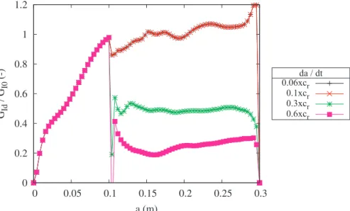
opening speed, the bigger the kinetic energy, and the less energy released. 2.5. Modelling of the moving crack in a pipe under pressure
The modelling of the moving crack in a liquid-pressurized polymer pipe is investigated. It is more complex as boundary conditions point of view than the pre-stressed pipe but more representative of the real application and standard tests. As a material point of view, the critical case is considered. Indeed the internal pressure is applied to be constant even during the dynamic propagation, i.e., the main crack is running faster than the decompression waves in the liquid and no leak of the liquid is modelled during dynamic fracture. According to the numerical results, the dynamic energy release rates are compared to the quasi-static energy release rateGI 0
which is computed without the variation of the work of external forces (cf.Appendix B). As the results of the pre-stressed pipe, the
Fig. 2. Energy release rate and energies vs. crack length for a pipe of dimensionsR=4.83BandL=20R(imposed displacement limit conditions). The total length L of the pipe for the numerical results presented herein is 20 times the mean radius R,R=(Ri+Re)/2, of the pipe with Riand Re
respectively the internal and external radius of the pipe. B is the thickness of the pipe. GIBTis the analytical solution of the energy release rate
energy release rates stabilize after a crack length of5Reand decrease with the crack velocity (see inFig. 4). As explained here[30]the
dynamic energy release rateGIdof the quasi-static (0.01cR) crack is about 300 times ofGI 0. This means that the elastic energy released
from that stored in the structure becomes a second order parameter in the energy balance sheet. The value ofGIdis in the case of
pressurized pipe dominated by the work of external forces. The influence of the wall thickness is also studied.Fig. 4shows the evolution ofGIdfor 3 different pipe wall thicknesses. A similar tendency for the strained pipes (pre-stressed by imposed
displace-ments) can be observed, the energy release rate increases with the wall thickness.
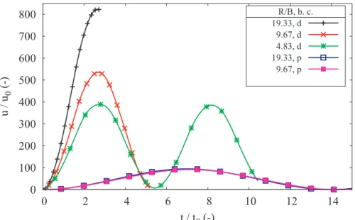
2.6. Free frequencies of the fractured ring
As shown in the simulation results, it appears clearly that the opening speed of the fractured pipe influences considerably the dynamic energy release rateGId. This can be explained by linking the free frequencies of the fractured pipe to the dynamic correction
Fig. 3. Dynamic energy released rate values vs. normalised crack length for various crack tip velocities and wall thickness B in a strained pipe (imposed displacement boundary conditions).
Fig. 4. Dynamic energy release rate values vs. crack length for various crack tip speeds and thickness B in a pressured pipe (imposed load boundary conditions). G0.01cRis the energy release rate of the quasi-static crack (0.01cR).
factors. A fractured ring is therefore modelled to study the free frequencies of the fractured pipes (seeFig. 5). For a straight beam, the well known dynamic equation of equilibrium takes the formρyS¨ +EIδ y=0
δx
4
4 . For a fractured ring which can be considered as a
curved beam, the dynamic equation of equilibrium is not so simple but the free frequencies are still linked toω = EI
ρS
0 . Considering a
rectangular section beam,ω0becomes
B E ρ
2 3 . To analyse dimensionless values, one can use the time associated to the free frequency
of such a beam which isτ =R
ω
0 2
0. For dimensionless displacements,u =
FR EI
0 3
is used, F being the force transmitted before fracture corresponding toF
2
BT (cf. Eq.(A.1)) for imposed displacements at poles, or 〈 〉σ BLfor imposed internal pressures (cf.Appendix B).
Fig. 6 shows the free-frequencies of a pre-stressed or pressurized pipe. However, for the pressurized one, whatever the wall thickness, the free-frequencies of a fractured ring are more or less the same. For a pre-stressed one, the thinner the wall thickness is, the faster the opening velocity of the fractured ring is, and the more important the dynamic correction is. These observations confirm the deduction from numerical results.
2.7. Discussion
The“dynamic correction factors” presented inFig. 7correspond to the total fracture work in the dynamic regime divided by the total fracture work for a crack velocity equal to0.01cR, i. e. to the quasi-static total fracture work.Fig. 7shows results for imposed
displacements and pressure for three wall thicknesses B. It appears clearly that the“structural” energy release rateGIdis strongly
dependant on the wall thickness. The thinner the wall is, the bigger the opening of the fractured ring is and the lower the energy release rate is. This effect is boosted by the boundary conditions in pressure case. The energy released is directly linked to the opening speed of the fractured ring. For the sake of simplicity, our model ensures a constant pressure in the pipe which is not realistic for crack velocities lower that the compressive waves speed in the liquid inside the pipe. Nevertheless, even with this simplification, the problem of analysing dynamic fracture in this case is shown to be complex and strongly dependant on the crack velocity and on the
wall thickness. It is expected that the energy released is also strongly dependant on the pressure decrease and distribution inside the pipe. Hence, it can be concluded that tests with internal gas pressure are not well suited for characterizing the dynamic fracture of the material[5,6].
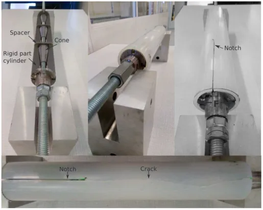
3. Experimental investigations for cracks running in strained pipe 3.1. Experimental set-up
Based on these numerical results a specific experimental set-up has been used to ensure RCPs in PS2 (seeFig. 9)[30]. The loading method of PS2 is presented inFigs. 8 and 9. The main objective is to pre-stress as uniformly as possible polymer pipes with imposed interior relative displacements (δ) to increase the stored elastic energy in the pipe. The loading system is a combination of three serial modules separated by spacers presented inFig. 9-up left. The loading system isfirst adjusted toRi. It is then introduced in the pipe
and is constrained by friction between the internal wall of the pipe and metallic pieces. The global rotation of the loading system is
Fig. 6. Normalised displacements vs. normalised time for opening a fractured ring. In the legend, d refers to imposed displacement et p to imposed load.
Fig. 7.“Dynamic correction factors” vs. crack velocities for various wall thickness for boundary conditions (b. c.) corresponding to strained (d) and pressured pipes (p).
therefore not possible. The loading system with the pipe is then clamped on a base. Radial force F is applied to the internal surface of the pipe wall by a pair of rigid part-cylinders (2), each of which loads approximately 18% of the circumference. The two part-cylinders are driven outwards by steel cones (1) which, while prevented from rotating by friction, are driven axially along a threaded rod rotated manually by the experimenter (seeFig. 8). The pre-stress of the pipe is stopped and maintained at constant δ by stopping the rotation of the threaded rod. A mode I fracture test is considered. It is noted that this loading system at the poles induces bending at the opposites poles (90 and 270° points). The circular pipe begins to deform therefore in an ellipse during the loading. A significant relaxation time (approximately 15 times the loading time) is considered before initiation. The crack is then initiated artificially with
δ
θ
Fig. 8. Principle of pre-stressed pipe test developed at the laboratory. The load is distributed on approximately 18% of the circumference of the pipe with the help of a pair of rigid part-cylinders (2) displacements δ which are ensured by the cone (1) translation on the threaded rod. The notch N is positioned at θ = −π2.
the help of an external impact on a razor blade in contact with the notch tip (see inFigs. 10-right). The notch is positioned atθ= −π
2
compared to the poles. The quasi-static energy release rateGI 0can be analytically estimated with the help of Eq.(A.2)or numerically
with a global energy balance. The crack path history is captured with the help of a high speed camera (Photron 106 APX-SA5) at 40000 frames per second with a resolution of 704∗256. Knowing the average crack tip velocity 〈 〉ȧ a numerical estimate of the consumed energy by the materialGIDto ensure a RCP is possible by taking into account inertia effects.
3.2. Material
The material under study is a polyamide 11 BESNO TL grade provided by Arkema. It was supplied as initially extruded pieces of pipe. The PA11 under study is a semi-crystalline polymer. A degree of crystallinity of 22% has been measured by Differential Scanning Calorimetry analysis for PA11 pipe. The dynamic elastic modulus Ed(see Eq.(1)) has been obtained by ultra-wave analysis
and is equal to 1620±82 MPa with ν = 0.43 and ρ = 1040 kg m−3. The mean ultra-wave velocity〈 〉vu measured in a pipe is equal to
2100±46 m s−1. The standard deviation has been considered for 10 measurement made on 5 different pipes. The viscoelastic be-havior of the polymer is approximated with the only dynamic elastic modulus Edas described here[31].
= + − − E ρv ν ν ν (1 )(1 2 ) 1 d u2 (1)
Fig. 10. Typical images of high speed camera with a 4 104images per second sampling rate during rapid crack propagation in polymer pipe ensured
with the help of an experimental set-up. Time =t 0 μs is chosen like reference point where the crack begins to propagate in dynamic state. At time =
t 325 μs the pipe is almost completely fractured. The arrow highlights the crack tip location during RCP. Att=275 μs a macroscopic crack branching is observable. At =t 800 μs fragments are caused by the sprayed paint which is used to highlight the image contrast.
3.3. Experimental results
Fig. 10presents a dynamic fracture of polyamide pipe (B4-see inTable 1), recorded using a high speed camera. The entire test is performed at room temperature. Five pipes are fractured with the help of the experimental device. Pipe dimensions are: L = 300 mm, b = 4 mm,Ri= 21 mm and the notch lengthln≈5Re≈120 mm. The notch length is defined with the help of numerical results. A
quasi-permanent regime of propagation is supposed to be reached. The mean measured crack tip velocity at macroscopic scale
≈ ±
ȧ 420 20 m s−1≈0.6cRbefore and after branching. It is deduced at this scale that the crack velocity does not change. The crack
propagates therefore at a relatively constant macroscopic velocity. A crack branching event is seen before t = 325μs inFig. 10. The crack path is known to depend on the available energy. The bigger the available energy, the bigger the dissipated energy by creating fracture surface. InFig. 10the available elastic energy stored in the structure is enough to propagate one straight crack with two branches. Inertia effects are supposed to induce branching at 0.6cRas demonstrated by Yoffe[15].〈GI 0〉is estimated with the help of
Eq.(A.2)to be equal to approximately7.5±0.9kJ m−2. The amount of fracture surface area has been calculated as the thickness times the crack length for each sample. At0.6cRwith an averaged dynamic correction of 0.2 estimated with the help of numerical
results (seeFig. 11), the mean dynamic fracture energy〈GID〉= 1.5±0.1 kJ m−2.
3.4. Fracture surface analysis
Fracture surface analyses have been realised with the help of a scanning electron microscope. B1 and B3 samples are presented in
Fig. 12at two different scales. At macroscopic scale, it is observed that the fracture surface roughness is different between each samples. B1 concerns a straight crack propagation contrary to B3 which has been observed just before a crack branching. The fracture surface seems to be rougher at the bottom of the image in B3 than in B1. The evolution of the roughness in the thickness is not homogeneous. This highlights as expected that the stress state in the thickness is not uniform. This is due to the loading system which induces radial force only at two opposite poles. The two other poles are free to move inwards. It is difficult to see in these images if the crack front on the inner surface propagates faster than the crack front on the external surface. Crack arrest marks should be analysed to observe it. At microscopic scale (down) the spherulitic microstructure of the PA11 is highlighted. At this scale the crack path is non-trivial. The crack propagates through the spherulites which can probably modify the stressfield at the crack tip. These analyses show that the LEFM approximation of the fracture surface as a mean plane is not relevant. The fracture surface roughness and therefore the fracture surface area should be considered in the estimate ofGID. The critical dynamic energy release rate GIDccould
then be estimated. By considering the amount of projected surface area (B times a)GIDis overestimated. A relevant estimate of the
minimal value ofGIDis not possible.
4. Discussion and conclusions
It has been shown that the analysis of the dynamic fracture mechanism in polymer pipe is a rather complex matter and depends strongly on the boundary conditions, the relative wall thickness of the pipe and the crack tip velocity. A preliminary numerical structural analysis has been made to study these effects which are insensitive of elastic material parameters. As explained here[30], the dynamic energy release rateGIdis significantly different between a crack running in pre-stressed or pressurized pipe. In
pres-surized pipe, the work of external forces dominates in the Griffith energy balance. That is why, forȧ≈0.01cRthe dynamic energy
release rateGIdis about 300 times ofGI 0. A relevant estimate ofGIdfor a pressurized pipe is not guaranteed. The estimate ofGIdis
moreover strongly dependant on the relative wall thickness whatever the boundary conditions are:
•
For the pressurized pipe, whatever the wall thickness, the free-frequencies of a fractured ring are more or less the same. For a pre-stressed one, the thinner the wall thickness is, the faster the opening velocity of the fractured ring is, and the more important the dynamic correction is.Based on these results a specific experimental set-up is used for studying RCP in PA11 PS2. Imposed displacement boundary conditions allow to have an approximately L≈13R permanent dynamic regime of propagation i.e.GId is quasi-constant during
dynamic crack propagation. Some conclusions can be made on the material behaviour:
•
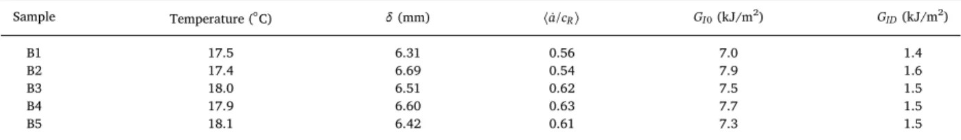
The crack tip velocity is observed not to change ( ≈ȧ 0.6cR) at macroscopic scale whatever the available stored energy in theTable 1
Quasi-static and dynamic energy release rates for PA11 pipes.
Sample Temperature (°C) δ(mm) 〈a ċ/R〉 GI 0(kJ/m2) GID(kJ/m2) B1 17.5 6.31 0.56 7.0 1.4 B2 17.4 6.69 0.54 7.9 1.6 B3 18.0 6.51 0.62 7.5 1.5 B4 17.9 6.60 0.63 7.7 1.5 B5 18.1 6.42 0.61 7.3 1.5
structure before initiation and whatever the crack configuration (straight crack or crack branching).
•
Fracture surface analyses suggest that the crack path is not trivial and different between each sample. As for RT-PMMA, it seems that the lower the energy release rate the smoother the fracture surface. The microscopic crack velocity should therefore probably change as a function of the available energy release rate. The bigger the energy release rate the bigger the microscopic crack length the bigger the microscopic crack velocity.•
A relevant estimate of the critical dynamic energy release rate GIDc is difficult since the amount of created surface area is notconsidered. A more appropriate estimate ofGIDas a function of the amount of created fracture surface (and not the thickness times
Fig. 11. Evolution of the energy release rate GIdas a function of the crack tip velocity and the crack length for a strained pipe.
Fig. 12. Typical images of fracture surface roughness of PA11 obtained with a scanning electron microscope. Samples B1 and B3 have been fractured with the pipe loading device presented herein inFig. 8. The arrow defines the crack propagation direction.
the crack length) should be considered as it has been suggested for rubber toughened polymer[24,25]tofinally access the critical dynamic energy release rate GIDc.
This kind of approach to limit unwanted structural effects has lead us to pre-stress pipe with imposed displacement contrary to full- and lab-scale tests which consider a liquid-pressurized pipe. This controlled solicitation allows to reveal the relevant material behaviour. In the case of RCPs in PS2 PA11 it is observed that contrary to full- and lab-scale tests:
•
the crack tip velocity is bigger than the decompression wave velocity, i.e. structural effects do not affect the dynamic of crack propagation with a limited velocity which will not be a ratio of the Rayleigh wave speed. That is why in this case the crack branching velocity is reached.•
“Ring-off” and “snake” mechanisms do not appear during dynamic propagation. Appendix A. Dynamometric ring modelBeam theory allows to obtain a quasi static reference analytical solution corresponding to the steady state regime in a pipe of infinite length, i. e. without any border effect. Considering a pipe of internal radiusRiand external radiusRethe force F to apply to
deform the ring with a δ relative displacement of the poles is given by: = − F πEIδ π R 4 ( 8) BT 2 3 (A.1) where E is the Young’s modulus of the material, I the second moment of area of the beam and R the mean radius of the pipe. I is equal to(Re−Ri)3b/12 where b is the thickness of the ring and R is equal to(Ri+Re)/2. The elastic energy is thus equal to 1/2 F δBT for the
entire ring. The energy release rate in the steady state regime is obtained by considering that an increase of Δa of the crack length in an infinitely long pipe corresponds to the passage of a slice of length Δa far in front of the crack tip far below the crack tip. The energy release rateGI is thus equal to released energy divided by the created surface, i. e. ( 1/2F δBT )/(Δa(Re−Ri)) where I is equal to
− R R δ ( e i)3 a/12. = − − + G πE R R δ π R R 8 ( ) 3( 8)( ) IBT e i e i 2 2 2 3 (A.2)
Appendix B. Pipe under pressure
Considering a pipe under an internal pressure p, the stress state varies only with r in axial coordinatesr θ, , z. For thin shells, typically for(Re−Ri)≪Ri, the variation with r is not significant and it can be assumed at first glance that the stress fields are uniform.
An approximate solution for the stress state is then easy to derive from equilibrium. The average stresses, an average value being denoted〈 〉σ, are 〈 〉 = 〈 〉 ≈ − − σθθ , σ pR R R rr p ( ) 2 i e i and 〈 〉 = − − σzz pR R R i e i 2
2 2. Assuming linear isotropic elasticity, the orthoradial strain is equal to
〈∊ 〉 = 〈θθ (σθθ〉− 〈ν σrr〉− 〈ν σzz〉)/E. The elastic energy for a pipe of length b is equal toWela.=πR pi2 〈∊ 〉θθbbefore fracture. The part of the
total released energy associated to these elastic energy is equal to =
−
GI0 (RWelaR b)
i e
. .G
I 0 is not the energy release rate since during
fracture both the elastic energy, the work of external forces and the kinetic energy will vary. These variations depend on the crack tip velocity– or more exactly location vs. time – and on the loss of pressure associated to the opening of the crack. The last point presents considerable difficulties for numerical modelling. NeverthelessGI 0 is useful to compare the order of magnitude of work done by
external forces during a test to that of the energy available for fracture at initiation of the crack. For the numerical simulations presented herein, the stress 〈σθθ〉 =0.
⎜ ⎟ = = ⎛ ⎝ − + − + − − ⎞ ⎠ G G πp E R R R νR R R νR R R R R ( ) 2( ) 2( )( ) I Ip i e i i e i i e i e i 0 2 3 2 2 4 2 2 (B.1) In the case of negligible radial and longitudinal stresses, i. e.σθθ≫σrr andσθθ≫σzz, an approximate solution gives:
= ≈ − G G πp R E R( R) I Ip i e i 0 2 3 2 (B.2) References
[1] Leevers P. An engineering model for rapid crack propagation alongfluid pressurized plastic pipe. Eng Fract Mech 2012;96:539–57.
[2] Mason J, Chen J. Establishing the correlation between s4 and full scale rapid crack propagation testing for polyamide-11 (pa-11) pipe. Plastic pipes XIII 2006. [3] Shannon RWE, Wells AA. Brittle crack propagation in gasfilled pipelines—a model study using thin walled unplasticised pvc pipe. Int J Fract 1974;10(4):471–86. [4] Kanninen M, O’Donoghue P. Research challenges arising from current and potential applications of dynamic fracture mechanics to the integrity of engineering
structures. Int J Solids Struct 1995;32(17):2423–45.
[5] Greig J, Leevers P, Yayla P. Rapid crack propagation in pressurised plastic pipe-I. Full-scale and small-scale rcp testing. Eng Fract Mech 1992;42(4):663–73. [6] Yayla P, Leevers P. Rapid crack propagation in pressurised plastic pipe-ii. critical pressures for polyethylene pipe. Eng Fract Mech 1992;42(4):675–82.
[7] O’Donoghue P, Kanninen M, Leung C, Demofonti G, Venzi S. The development and validation of a dynamic fracture propagation model for gas transmission pipelines. Int J Press Vessels Pip 1997;70(1):11–25.
[8] Zhuang Z, O’Donoghue P. Determination of material fracture toughness by a computational/experimental approach for rapid crack propagation in pe pipe. Int J Fract 2000;101(3):251–68.
[9] Ivankovic A, Venizelos G. Rapid crack propagation in plastic pipe: predicting full-scale critical pressure from s4 test results. Eng Fract Mech 1998;59(5):607–22. [10]Greenshields C, Venizelos G, Ivankovic A. Afluid-structure model for fast brittle fracture in plastic pipes. J Fluids Struct 2000;14(2):221–34.
[11]Williams J, Venizelos G. A perturbation analysis of rapid crack propagation in pressurised pipe. Int J Fract 1999;94(2):161–76.
[12]Beguelin P, Fond C, Kausch HH. Fracture mechanics at intermediate rates of loading: the influence of the acceleration on compact tension tests. J Phys IV 1997;7(C3):867–72.
[13] Beguelin P, Fond C, Kausch HH. The influence of inertial effects on the fracture of rapidly loaded compact tension specimens. Part a: loading and fracture initiation. Int J Fract 1998;89(1):85–102.
[14] Ferrer JB, Fond C, Arakawa K, Takahashi K, Beguelin P, Kausch HH. The influence of crack acceleration on the dynamic stress intensity factor during rapid crack propagation. Lett Fract Micromech 1998;87(3):77–82.
[15] Yoffe EH. The moving griffith crack. Phil Mag 1951;42(7):739–50. [16] Broberg KB. The propagation of a brittle crack. Arkiv for Fysik 1960;18:159.
[17] Freund LB. Crack propagation in an elastic solid subjected to general loading-i. constant rate of extension. J. Mech. Phys. Solids 1972;20:129–40. [18] Cros PE, Rota L, Cottenot CE, Schirrer R, Fond C. Experimental and numerical analysis of the impact behaviour of polycarbonate and polyurethane multilayer. J
Phys IV 2000;10(Pr9):671–5.
[19] Irwin G, Dally J, Kobayashi T, Fourney W, Etheridge M, Rossmanith H. On the determination ofa k−̇ relationship for birefringent polymers. Exp Mech 1979;19:121–8.
[20]Sheng J, Zhao YP. Two critical crack propagating velocities for pmma fracture surface. Int J Fract 2000;98:L9–14. [21]Rosakis A, Zehnder A. On the dynamic fracture of structural metals. Int J Fract 1985;27:169–86.
[22]Ponson L, Bonamy D. Crack propagation in brittle heterogeneous solids: material disorder and crack dynamics. Int J Fract 2010;162(1–2):21–31. [23] Fineberg J, Bouchbinder E. Recent developments in dynamic fracture: some perspectives. Int J Fract 2015;196(1–2):33–57.
[24] Kopp JB, Schmittbuhl J, Noel O, Lin J, Fond C. Fluctuations of the dynamic fracture energy values related to the amount of created fracture surface. Eng Fract Mech 2014;126:178–89.
[25] Kopp JB, Schmittbuhl J, Noel O, Fond C. A self-affine geometrical model of dynamic rt-pmma fractures: implications for fracture energy measurements. Int J Fract 2015;193(2):141–52.
[26] Fond C, Schirrer R. Dynamic fracture surface energy and branching instabilities during rapid crack propagation in rubber toughened pmma. Notes au CRAS, Series IIb 2001;329(3):195–200.
[27] Fond C, Schirrer R. Influence of crack speed on fracture energy in amorphous and rubber toughened amorphous polymers. Plast, Rubb Compos, Macromol Eng 1997;30:116–24.
[28] Fond C, Schirrer R. Fracture surface energy measurement at high crack speed using a strip specimen: application to rubber toughened pmma. J Phys IV 1997;7(C3):969–74.
[29] Sharon E, Fineberg J. Microbranching instability and the dynamic fracture of brittle materials. Phys Rev B– Condens Matter Mater Phys 1996;54(10):7128–39. [30] Kopp JB, Lin J, Schmittbuhl J, Fond C. Longitudinal dynamic fracture of polymer pipes. Eur J Environ Civil Eng 2014;18(10):1097–105.