HAL Id: hal-02302118
https://hal.archives-ouvertes.fr/hal-02302118
Submitted on 7 Jul 2020
HAL is a multi-disciplinary open access
archive for the deposit and dissemination of
sci-entific research documents, whether they are
pub-lished or not. The documents may come from
teaching and research institutions in France or
abroad, or from public or private research centers.
L’archive ouverte pluridisciplinaire HAL, est
destinée au dépôt et à la diffusion de documents
scientifiques de niveau recherche, publiés ou non,
émanant des établissements d’enseignement et de
recherche français ou étrangers, des laboratoires
publics ou privés.
Optimal Thrust Allocation Strategy of Electric
Propulsion Ship Based on Improved Non-Dominated
Sorting Genetic Algorithm II
Diju Gao, Xuyang Wang, Tianzhen Wang, Yanping Wang, Xiaobin Xu
To cite this version:
Diju Gao, Xuyang Wang, Tianzhen Wang, Yanping Wang, Xiaobin Xu. Optimal Thrust Allocation
Strategy of Electric Propulsion Ship Based on Improved Non-Dominated Sorting Genetic Algorithm
II. IEEE Access, IEEE, 2019, 7, pp.135247-135255. �10.1109/ACCESS.2019.2942170�. �hal-02302118�
Digital Object Identifier 10.1109/ACCESS.2019.2942170
Optimal Thrust Allocation Strategy of
Electric Propulsion Ship Based
on Improved Non-Dominated Sorting
Genetic Algorithm II
DIJU GAO1, XUYANG WANG 1, TIANZHEN WANG1, YIDE WANG 1,2, AND XIAOBIN XU 3
1Key Laboratory of Marine Technology and Control Engineering, Ministry of Transport, Shanghai Maritime University, Shanghai 201306, China 2Institut d’Electronique et de Télécommunications de Rennes, UMR CNRS 6164, Universite de Nantes, 44300 Nantes, France
3School of Automation, Hangzhou Dianzi University, Hangzhou 100084, China
Corresponding author: Xuyang Wang ([email protected])
This work was supported in part by the National Natural Science Foundation of China under Grant 61673260 and Grant 61304186, and in part by the NSFC-Zhejiang Joint Fund for the Integration of Industrialization and Informatization under Grant U1709215.
ABSTRACT The azimuth thruster is widely used in electric propulsion ships due to its excellent perfor-mance. The thrust allocation (TA) method of multi-azimuth thruster is the key technology in ship motion control. The purpose of TA is to accurately distribute the thrust and angle of each thruster to provide the vessel the required force and moment. A TA strategy based on the improved non-dominated sorting genetic algorithm II (INSGA-II) is developed in this study. The algorithm introduces the differential mutation operator in the differential evolution (DE) to replace the polynomial variation in NSGA-II, which improves the local optimization ability of the algorithm. The effectiveness of the TA strategy based on INSGA-II algorithm is illustrated by simulations.
INDEX TERMS Electric propulsion, multi-azimuth thruster, thrust allocation, optimization, NSGA-II.
I. INTRODUCTION
Due to the breakthrough in efficiency, maneuverability, relia-bility and flexirelia-bility of operations, the application of electric propulsion is widespread [1]. The azimuth thruster can make a 360-degree revolution around the axis and achieve maxi-mum thrust in any direction. It can make the ship rotate, move laterally, and retreat in a special driving operation. Azimuth thrusters are installed on various engineering vessels, such as tugboats, floating crane vessels, dredgers, ferries, and work-ing pontoons [2], [3]. In order to improve the maneuverability, efficiency and system dependability of engineering vessels, more than two propellers are usually deployed. For example, tugs are equipped with multiple propellers at the stern, mid-ship and bow [4]. However, on the one hand, the interaction of the propellers causes asymmetric and irregular dynamic tur-bulence characteristics in the propeller propulsion operation, which poses a challenge to the control of the ship. On the other hand, the propulsion load fluctuates drastically under complex sea environment, making the power distribution of
The associate editor coordinating the review of this manuscript and approving it for publication was Juntao Fei.
each propeller unbalanced. Therefore, the accurate allocation of each azimuth thruster is a key issue to enable the electric propulsion ship to obtain the required force and moment.
In complex sea conditions, the ship usually has six degrees of freedom (DOFs) due to the action of wind, current and waves. The movements can be decomposed into two parts: high frequency and low frequency motions. The high-frequency part is caused by the reciprocation and undulation of the wave. Active control of the high-frequency part may lead to repeated fluctuations in the control output, propeller wear, and grid variations. Therefore, the high-frequency component is generally removed by filtering, such that only three DOFs motions of ship are studied (surge, sway and yaw) [5]. For an electric propulsion ship equipped with azimuth thrusters, the system is an over-actuated system. The function of the thrust allocation (TA) is to use redundant propellers to select the optimal solution from propellers sat-isfying the control mapping relationship to improve the fault tolerance and maneuverability while reducing the power con-sumption. Therefore, the TA problem of the azimuth thrusters is essentially a constrained nonlinear multi-objective optimization problem.
D. Gao et al.: Optimal TA Strategy of Electric Propulsion Ship Based on INSGA-II
When the thruster direction is fixed or the thruster and rudder are fixed on a plane to provide the required thrust, the TA problem can be approximated as an unconstrained least squares problem. The problem can be solved by the explicit Moore-Penrose solutions [5], [6]. By introducing the mechanical constraints of the thruster, the constrained TA optimization problem can be solved by an iterative solution. Johansen proposed a quadratic programming (QP) based method to solve such problem [7]. For ships equipped with multiple azimuth thrusters, the thrust structure is complex and the feasible field of the variable is large. Liang proposed a method using the sequential quadratic programming (SQP) to solve the non-convex nonlinear optimization problem [8]. The real-time performance and local optimization capabili-ties of QP and SQP are excellent, while the ability to find the global optimal solution in a wide range is relatively poor. Therefore, the TA method based on the basic intelli-gent algorithms is proposed in [9], [10]. However, the basic intelligent algorithms have some drawbacks in terms of con-vergence speed and diversity. Some researchers have devel-oped the improved basic intelligent algorithms [11]–[13]. However, the convergence of the improved intelligent algorithms cannot be guaranteed. Based on the improved intelligent algorithms, Wu proposed the adaptive hybrid arti-ficial bee colony algorithm (AHABCC), which can adap-tively switch the search mechanisms based on the number of iterative solutions [14]. However, the search method com-bining the mutation operator in differential evolution (DE) with the social cognitive function of particle swarm opti-mization (PSO) is not perfect, and the control parameters need to be tested repeatedly. Hybrid algorithm based on the genetic algorithm (GA) and SQP was proposed by Zhao and Roh [15]. Guo proposed a new algorithm combining the biogeography-based optimization (BBO) and PSO [16]. However, the hybrid intelligent algorithms cannot guarantee the stability.
The main contributions of this paper are as follows: 1) NSGA-II is applied to deal with variables,
multi-constraints and non-convex objective function, which solves the optimal thrust allocation problem of electric propulsion ship with multi-azimuth thrusters.
2) The thrust allocation of electric propulsion ship with multi-azimuth thrusters requires not only the control accuracy and maneuverability of the ship, but also the reduction of energy consumption and mechanical wear, which often lead to the suboptimal solution of the propellers state. The improved NSGA-II is intro-duced, which uses the difference operator in differential evolution algorithm to improve the mutation opera-tion. INSGA-II is applied to the TA, which solves the problem that the state of the propellers is easy to fall into local optimum. The proposed ship thrust alloca-tion algorithm reduces the energy consumpalloca-tion of the thrusters and improves the control precision.
3) By comparing INSGA-II with SQP, the average thrust errors of INSGA-II in 3 DOFs motions of ship
(surge, sway and yaw) are 29.7%, 25% and 22.5% of those of SQP, respectively. The maximum power consumption and average power consumption of INSGA-II are 86.1% and 80.4% of those of SQP, respectively. The simulation results verify the effective-ness of the proposed thrust allocation algorithm based on INSGA-II.
The remaining of the paper is organized as follows. Section II presents the mathematical model for
multi-objective optimization of thrust allocation problem.
Section III presents an improved NSGA-II algorithm and applies it to thrust allocation. In Section IV, the proposed algorithm is applied to the Cybership III by simulations, and the obtained results are analyzed in detail. Section V concludes the paper.
II. THRUST ALLOCATION MATHEMATICAL MODEL
A. PROBLEM OVERVIEW
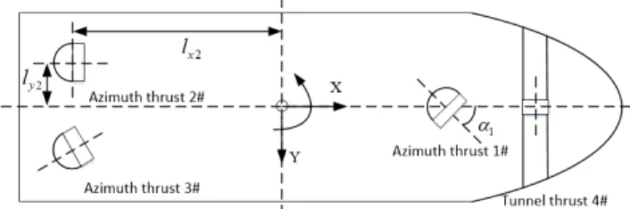
The TA optimization model is established based on Cyber-Ship III tug model with a micro scale of 1:30 [4], [17], [18]. The layout of the thruster is shown in Fig.1. 1#-3# are all azimuth thrusters and 4# is a tunnel thruster. The tunnel thruster is the side thruster of the ship and its direction cannot be changed. In this paper, subscripts i and j both indicate the number of the propeller (i = 1, 2, 3; j = 1, 2, 3, 4).
FIGURE 1. Thrust layout of CyberShip III.
Geodetic coordinate system XEOYE and the hull
coordi-nate system XOY are used to describe the movement of the ship in three DOFs. Both XY and XEYE are coincided with
the horizontal plane. The position and yaw angle vector of the ship in the geodetic coordinate system is denoted by η = [x, y, ψ]T, and the velocity vector of the three DOFs in
the hull coordinate system is v = [u, v, r]T. The relationship betweenη and v can be described by [5]
˙ η = R(ψ)v (1) where R(ψ) = cos(ψ) −sin(ψ) 0 sin(ψ) cos(ψ) 0 0 0 1 (2)
The kinematic equation of the hull can be expressed as:
M˙v + C(v)v + D(v)v =τ (3) where M is the inertia matrix of the hull; C(v) represents the Coriolis centripetal force matrix; D(v) is the damping
matrix [4]; andτ is the resultant force or torque generated by the driving system, which consists of the working state of the propeller and the thrust structure:
τ = B(α)f (4)
where f = [f1, f2, f3, f4]T is the thrust vector composed of each thruster; f1− f4are the thrusts generated by the 1#-4# thrusters; α = [α1, α2, α3]T .α1 ∼ α3 are the angles of the thruster 1#-3#, respectively. The direction of the tunnel thruster cannot be changed. B(α) ∈ R3×4is the thrust struc-ture matrix representing the mapping relationship from the thrust of each propeller fito the resultant force or momentτ.
The thrust structure vectors of the azimuth thruster and the tunnel thruster are ba(αi) and bt, respectively [19], they are
given by ba(αi) = cosαi sinαi sinαilxi−cosαilyi , bt = 0 1 lx4 B(α) = [ba(α1), ba(α2), ba(α3), bt] α = [α1, α2, α3]T (5)
The controller gives the desired resultant force or moment τd = [τx, τy, τz]T according to the current ship positions
η = [x, y, ψ]T,v = [u, v, r]T.τ
xandτyare the forces in the
X and Y directions, respectively, andτzis the yaw direction
torque. The thrust allocation algorithm assigns the respective state quantitiesαiand fjto each thruster according toτd, and
the resultant force or momentτ generated by the final thrust system. The block diagram of the ship motion control system is shown in Fig.2.
FIGURE 2. Block diagram of the ship motion control system.
B. THRUST ALLOCATION OPTIMIZATION MODEL
Based on the CyberShip III tug model, the forces of the X and Y axes and the total torque can be formulated as follows:
fx = f1cosα1+ f2cosα2+ f3cosα3
fy= f1sinα1+ f2sinα2+ f3sinα3+ f4
m = −f1sinα1lx1+f1cosα1ly1+ f2sinα2lx2+ f2cosα2ly2 +f3sinα3lx3− f3cosα3ly3− f4lx4
(6) where lj =[lxj, lyj]Tis the position vector of the thruster in the
hull coordinate system; lxj and lyjare the distances between
thruster j# and the X axis and Y axis, respectively.
1) TOTAL POWER CONSUMPTION OF THRUSTERS
For an electric propulsion system, the load on the propulsion unit generally accounts for the largest proportion of the entire power system. The TA of propellers will have a great impact on the entire electrical load, and the repeated fluctuations in the propulsion system power consumption will lead to the collapse of the power system [14]. Minimizing the power of the propulsion system under the premise of satisfying the thrust demand can not only reduce the energy consumption, but also stabilize the output power at a lower level and improve the overall system safety performance. Therefore, the mathematical connection between the thrust generated by the thruster and the corresponding power consumption should be established, and the power consumption should be promoted as a goal to be minimized. The overall power consumption of the thruster can be constructed as [20], [21]:
Pw= 4 X j=1 cj fj 3 2 (7)
where cjis the power factor of the thruster.
2) THRUST ERROR
The TA algorithm assigns the state quantitiesαi and fj to
the corresponding thruster according toτd, and the resultant
force τ generated by the propulsion system. The error s betweenτdandτ causes a drop in the control accuracy,
result-ing in a deviation in the position of the vessel. Therefore, one of the optimization goals of thrust allocation is to minimize the error. The quadratic penalty term Je for error s can be
defined as
s =τd−τ (8)
Je =sTQs (9)
where Q = diag(wx, wy, wm) represents the penalty weight
of the resultant force error on the three DOFs [12].
3) MECHANICAL LIMITATIONS OF THRUSTERS
The mechanical limitations of thrusters are mainly reflected in the following aspects: the thrust generated by the full-rotation thrusters at the maximum power when driving ahead and reversing, the change rate of thrust value, the change rate of propeller angle, and the repeated wear limitation of thrusters. Let the maximum output forward thrust and reverse thrust of the propeller be fjmaxand fjmin, respectively; fj0be the thrust generated by the propeller in the previous step, and fjp be the thrust at the current moment. And let αimax and αimin be the upper and lower limits of the propeller rotation angle, respectively;αi0be the angle of the propeller in the previous step, andαip be the angle of the propeller
at the current moment. Due to the mechanical limitations of the thruster, the thruster angle and thrust cannot be transient. Let fjmin and fjmax be the lower and upper limits of the thrust change rate;αiminandαimaxbe the lower and upper limits of the angle change rate of the thrusters, respectively.
D. Gao et al.: Optimal TA Strategy of Electric Propulsion Ship Based on INSGA-II
The constraints can be expressed as follows:
fjmin ≤ fjp≤ fjmax αimin ≤αip≤αimax 1fjmin ≤ fjp− fj0 ≤1fjmax 1αimin ≤ αip−αi0 ≤1αimax (10) Letαp=[α1p, α2p, α3p]T,α0=[α10, α20, α30]T. In order to avoid the frequent change of the angle of the full-turn pro-peller, causing the mechanical equipment wear, the following quadratic penalty term Jis introduced for the angle change amount1α = αp−α0:
J=(αp−α0)T(αp−α0) (11)
where = diag(w1, w2, w3) is the penalty matrix for each angular variation. For example, in the tugboat model studied in this paper, the rotational cost of the full-turn propellers 2#, 3# will be higher, and the corresponding weights in the matrix will be designed to be higher [4].
4) SINGULAR STRUCTURE
In the study of TA, the singular thrust structure means that the current propulsion system cannot produce the resultant force or moment in the freedom of movement of the hull [22]. When approaching a singular structure, the thruster needs to produce a higher thrust output to meet the requirements of working conditions, essentially by reducing the propulsion efficiency in exchange for ship maneuverability. An increase in the thrust output of the propeller can result in more fuel consumption and grid fluctuations, which can even seriously affect the ship operation [23]. Therefore, one of the optimiza-tion goals of TA is to prevent the propulsion system from approaching its singular structure.
Therefore, the introduction of a singular structure penalty term Js allows the TA algorithm to make tradeoffs between
the optimal energy consumption and optimal mobility:
Js= δ
ε + det(B(α)BT(α)) (12)
where det(·) indicates the matrix determinant operation. In order to avoid numerical problems with a zero denomi-nator, parameter ε > 0 is set to be a very small value. δ is the weight of the singular value penalty term. The bigger the value ofδ-cjis, the more the TA algorithm is focused on the
maneuverability.
In summary, the optimization objective function of the TA problem can be expressed as follows:
min J (α, f , s) = min (Pw+ Je+ J+ Js) =min( 4 X j=1 cj fj 3 2 +sTQs + (α p−α0)T (αp−α0) + δ ε + det(B(α)BT(α))) (13) s.t fjmin≤ fjp≤ fjmax αimin≤αip≤αimax 1fjmin≤ fjp− fj0 ≤1fjmax 1αimin≤ αip−αi0 ≤1αimax (14)
III. THRUST ALLOCATION ALGORITHM
Although the traditional NSGA-II algorithm increases the population diversity through the crowding distance mecha-nism, there are still problems of poor distribution and local optimum [24], [25]. The long-term suboptimal solution of the propellers state will result in a decrease in energy efficiency and mobility. In recent years, many scholars have tried to improve the NSGA-II in terms of the convergence perfor-mance and the uniformity of the solution set distribution and apply it to different fields. Therefore, in this paper, we have introduced an INSGA-II and innovatively proposed a thrust distribution algorithm based on INSGA-II [26]. The applied INSGA-II has been improved in the mutation mode, and the differential mutation operator in differential evolution is introduced to improve the global optimization ability of the algorithm.
A. INSGA-II ALGORITHM
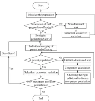
NSGA-II is multi-objective optimization algorithm based on genetic algorithm and Pareto optimal solution. The steps of the NSGA-II algorithm are: the initial population of size n is randomly generated firstly. After the non-dominated sorting, the first generation of the offspring population is obtained by some basic operations (selection, crossover, mutation) of the genetic algorithm. Then, the parent population and the offspring population are merged for fast non-dominated sorting. At the same time, the congestion degree is calculated for each individual in the non-dominated layer. The appro-priate individuals are chosen according to the non-dominated relationships and individual crowding to form the new parent population. Finally, a new generation of populations is gen-erated by selection, crossover and mutation operators of the genetic algorithm until the ending conditions of the program are met. The flow chart of the NSGA-II algorithm is shown in Fig.3.
It is limited to judge the distribution of individuals only from the size of crowding distance. When there is an error between the current thrust and the desired resultant force, the magnitude and variation range of the thrust error penalty term will be higher than other objective function terms. Solutions that meet the thrust balance conditions will rapidly develop offspring and dominant populations. Therefore, the differential mutation operator is introduced to avoid the premature convergence and local optimum [26], [27].
Specifically, for an initial population P0, there is a parental entity P1. The temporary offspring P2is generated by muta-tion operators as follows:
P2=βPr+(1 −β)P1 (15) where β ∈ [σmin, 1] is a real number that controls the amplification of the difference (Pr − P1) [28]. A number of
FIGURE 3. Flow chart of the NSGA-II algorithm.
existing studies provide a range of recommended values for β [29], [30]. β can be calculated according to the following scheme : β = max(σmin, 1 − βmax βmin ), if βmax βmin < 1 max(σmin, 1 − βmin βmax ), otherwise (16)
βmaxandβminare the maximum and minimum values of P1, respectively. σmin is the lower bound of β. In this paper, σmin=0.5 is used. The function of mutation operator in the early stage of evolution is to maintain the diversity of popula-tion. A larger value ofβ means a greater degree of influence. The operator is not affected by other factors, and can expand the search range to a wider range of search directions. The directional guidance of the difference vector is used to guide the population to search for the optimal solution.
Two important operators are included in the search method here: the threshold value and selection of adjacent individu-als. Two extreme endpoints of the non-dominated set F (k) are firstly identified under sub target k. E is the difference between the two extreme values. The threshold value Dk of
sub target k is calculated as follows:
Dk =
2E
|F (k)| − 1 (17)
where |F (k)| is the number of the elements in F (k). The distance threshold Dk will be dynamically adjusted with the
non-dominated set of the contemporary population F (k) [19]. The crowding distance Dk varies with the range of the
non-dominant set of the current population. With the pro-cess of evolution, the front of non-dominated set is evenly distributed.
In order to prevent the premature convergence, the selec-tion of adjacent individuals is very important. Firstly, sort the non-dominated set F (k) under sub target k; secondly, the distance between the two adjacent individuals is compared with the threshold value Dk. If the individual distance is
greater than or equal to Dk, the target values of the
adja-cent individuals under other sub-objects need to be further computed. If at least one pair of target values is not equal, the pair of adjacent individuals will not meet the requirements of evolution. The adjacent individual pair must perform a differential local search.
B. APPLICATION OF THE INSGA-II
The multi-objective optimization problem (13) of the min-imum overall power consumption, minmin-imum thrust error, minimum mechanical wear and maximum maneuverability is firstly established. Then the parameters to be optimized are determined, and the thrust and angle constraints (14) of the propeller are added. Finally, INSGA-II is designed to handle the multi-objective optimization, and the thrust and angle control quantities of each propeller are obtained.
The implementation steps of the algorithm are as follows:
Step1: Establish the optimization model for the minimum
overall power consumption, minimum thrust error, minimum mechanical wear, and maximum maneuverability for the TA problem, as shown in (13).
Step2: Select the corresponding constraints of the thrust
and angle constraints of the propellers, as shown in (14).
Step3: Use the desired surge, sway resultant force and
swaying moment as the input thrust command. Determine the parameters range of the thrust allocation system.
Step4: The INSGA-II is briefly summarized into the
fol-lowing steps:
Step4-1: Select the thrust and angle of the thrusters as the
input variables of the algorithm, and design the chromosome as Ch = {α1, α2, α3, f1, f2, f3, f4} according to the config-uration of the propellers. The original population Pt with
population size n was obtained by initializing the population.
Step4-2: A polynomial mutation is performed on Pt to
produce the first generation of offspring Qt.
Step4-3: Combine populations Pt and Qt, to get the Rt (a
population that temporarily stores population information).
Step4-4: Calculate the objective function value of the
individual in the population according to (13). A fast non-dominated sorting of Rt is obtained, and its former i-part
composition Fiis obtained.
Step4-5: Calculate the crowding distances for each
indi-vidual of Fiin the non-dominated layer, and sort the
individ-uals in descending order of crowded distance.
Step4-6: If Fi+ Pt < N, Pt = Pt∪ Fi, i = i + 1, go back to
Step4-4; otherwise, return to Step4-5. Select the first N − Pt
of the Fiinto Pt.
Step4-7: If t ≥ Gmax (Gmax is the maximum iteration number), the non-dominant individual in Pt is outputted and
D. Gao et al.: Optimal TA Strategy of Electric Propulsion Ship Based on INSGA-II
mutation to produce the offspring population Qt. Return to
Step4-3.
IV. SIMULATION RESULTS
A. SIMULATION PARAMETER SETTING
All of the simulations are completed via the Matlab R platform, version 2014B on a personal computer. The config-urations of the computer are CPU 2.80GHz, RAM 16.0GB, and 64-bit operation system. In this paper, the simulation experiment is carried out based on the CyberShip III tug model with a 1:30 reduction ratio. The length, breadth, draft and weight of the ship model are shown in Table 1. The max-imum forward thrust, maxmax-imum reverse thrust and maxmax-imum power of the thrusters are shown in Table 2 [4], [31]. Tfmax represents the maximum forward thrust, Tfminrepresents the maximum reverse thrust, and Pmaxrepresents the maximum power. The thruster layout of the simulation ship is shown in Table 3.
TABLE 1. Main dimensions of the Cybership III.
TABLE 2. Parameters of thrusters.
TABLE 3. Layout of ship thrusters.
The vessel moves from the initial state [0m 0m 0◦] to the desired position [10m 10m 30◦] and maintains the desired heading as shown in Fig.4. The desired longitudinal thrust, the lateral thrust, and the moment of 200s are shown in Figs.5-7.
FIGURE 4. Desired ship trajectory.
FIGURE 5. Desired longitudinal resultant force.
FIGURE 6. Desired lateral resultant force.
FIGURE 7. Desired moment.
The initial population size is n = 70, the number of iterations is Npmax = 100, the crossover probability is
Pc = 0.65. The algorithm has an optimized stall size of
Nps=10 and an optimization time limit of Tlim=300ms.
B. RESULTS ANALYSIS
Figs. 8-10 show the angles and thrust states of the three azimuth thrusters during the simulation. The yellow and blue lines represent the results of SQP and INSGA-II, respectively. Fig.11 shows the change in thrust of the tunnel thruster 4#. Since the tunnel thruster is fixed in direction, there is no angu-lar state. It can be seen from the figure that the range and rate of change of the angle and thrust of the thruster under SQP are greater than those of the INSGA-II algorithm. From the
FIGURE 8. Thrust and the angel of thruster #1.
FIGURE 9. Thrust and the angel of thruster #2.
FIGURE 10. Thrust and the angel of thruster #3.
mechanical properties of the propeller, we hope that the pro-peller will minimize the repeated wear and tear while meeting the desired demand. Obviously, the results of INSGA-II can better meet the requirements of actual working conditions.
According to (6), all thrusters produce a resultant force or moment in surge, sway and yaw. As shown in Figs. 12-14, the yellow and blue lines indicate the results under SQP and NSGA-II, respectively. The resultant
FIGURE 11. Thrust and the angel of thruster #4.
FIGURE 12. Results of longitudinal thrust.
FIGURE 13. Results of lateral thrust.
FIGURE 14. Results of moment.
force obtained by the INSGA-II algorithm is very close to the target τd. While the SQP algorithm takes more
time to reach the expected value when input τd changes.
And the maximum error Max and the average error Ave of the SQP algorithm compared to the INSGA-II algorithm are both large. Fig.12 shows the comparison of the results of SQP and INSGA-II with the desired resul-tant force in surge. Fig.13 shows the comparison of the results of SQP and INSGA-II with the desired resultant force in sway. Fig.14 shows the comparison of the results of SQP and INSGA-II with the desired moment in yaw. Among them, the orange and blue lines indicate the results under SQP and INSGA-II, respectively. The yellow line indicates the set of desired values. Table 4 shows that the average resultant force or moment errors of SQP in
D. Gao et al.: Optimal TA Strategy of Electric Propulsion Ship Based on INSGA-II
TABLE 4. Tracking errors of the two algorithms.
the direction of surge, sway and yaw are 0.1542 KN, 0.0988 KN and 0.0967 KNm, respectively. The average resul-tant force or moment errors of INSGA-II in three DOFs are 0.0458 KN, 0.0247 KN and 0.0218 KNm, respectively. The maximum resultant force or moment errors of SQP in three DOFs are 0.2292 KN, 0.1968 KN and 0.1970 KNm, respec-tively. However, the maximum resultant force or moment errors of the INSGA-II in three DOFs are 0.0987 KN, 0. 0499 KN, and 0. 0498 KNm, respectively. By comparing the results of INSGA-II with those of SQP, the average thrust errors of INSGA-II in surge, sway and yaw are 29.7%, 25% and 22.5% of those of SQP, respectively. This is because the SQP algorithm cannot accurately model the rate at which the thrust magnitude changes. The magnitude of the thrust obtained by the SQP algorithm changes frequently, and the desired force and torque cannot be accurately tracked. The repeated changes in the magnitude of the thrust and the fre-quent changes in the angle of the propeller cause mechanical wear of the propulsion device and do not conform to its physi-cal conditions. While the INSGA-II algorithm can prevent the azimuth thrust from changing the propulsion angle frequently while satisfying the combined demand.
The orange and blue lines in Fig.15 represent the power consumption of SQP and INSGA-II, respectively. As can be seen from Table 5, the average power consumption under SQP is 37.43W, while the average power consumption under INSGA-II is only 30.09W. The maximum power consump-tion under SQP is 98.42W, while the maximum power con-sumption under INSGA-II is 84.65W. The maximum power consumption and average power consumption of INSGA-II are 86.1% and 80.4% of those of SQP, respectively.
FIGURE 15. Comparison of power consumption.
TABLE 5.Power consumption comparison of the two algorithms.
Simulation results show that the proposed algorithm has better accuracy and lower average power consumption than the SQP algorithm. In order to achieve the same goals as the INSGA-II algorithm, SQP often needs to allocate a larger output to each thruster, resulting in a higher overall power consumption and peak power, as shown in Table 5. The SQP algorithm is based on the gradient estimation algorithm. When the feasible range of the thrust allocation is large, the local optimal solution may be obtained to meet the thrust demand to a certain extent but the target problem cannot be optimized. The INSGA-II algorithm can achieve higher energy efficiency because it can jump out of the local mini-mum region and instantly select the global optimal solution for multi-objective problems. It can change the angle of the full-turn propeller to meet the current combined forces and reduce the power consumption.
V. CONCLUSION
This paper proposes a TA method based on the INSGA-II algorithm. In order to improve the problem that the non-dominated individuals with large crowding distance and large solution density are present in the NSGA-II algorithm, the mutation operator in DE is introduced. Simulation results show that the INSGA-II algorithm has less power consump-tion and error than the SQP algorithm in handling the TA problem, and its computational scale has also been improved. This proves that the proposed strategy is successful and effec-tive. However, the improved NSGA-II algorithm has only been tested with simulated data, and the full-turn propeller is constantly evolving. Therefore, real data should be used for physical testing in the next step, and attempts should be made to introduce more specific operators to achieve better performance for the optimization problem.
REFERENCES
[1] J. F. Hansen and F. Wendt, ‘‘History and state of the art in commercial electric ship propulsion, integrated power systems, and future trends,’’ Proc. IEEE, vol. 103, no. 12, pp. 2229–2242, Dec. 2015.
[2] P. S. Wang, ‘‘Research on hydrodynamic performance of full-revolving propulsions,’’ Ph.D. dissertation, College Shipbuilding Eng., Harbin Eng. Univ., Harbin, China, 2007.
[3] C. O. Lim, B. C. Park, J. C. Lee, E. S. Kim, and S. C. Shin, ‘‘Electric power consumption predictive modeling of an electric propulsion ship considering the marine environment,’’ Int. J. Nav. Archit. Ocean Eng. vol. 11, no. 2, pp. 765–781, Jul. 2019.
[4] E. Ruth, ‘‘Propulsion control and thrust allocation on marine vessels,’’ Ph.D. dissertation, Dept. Mar. Technol., Norwegian Univ. Sci. Technol., Trondheim, Norway, 2008.
[5] T. I. Fossen, Guidance and Control of Ocean Vehicles. Hoboken, NJ, USA: Wiley, 1994.
[6] T. I. Fossen and S. I. Sagatun, ‘‘Adaptive control of nonlinear systems: A case study of underwater robotic systems,’’ J. Robotic Syst., vol. 8, no. 3, pp. 393–412, Jun. 1991.
[7] T. A. Johansen, T. I. Fossen, and P. Tøndel, ‘‘Efficient optimal constrained control allocation via multiparametric programming,’’ J. Guid., Control, Dyn., vol. 28, no. 3, pp. 506–515, 2005.
[8] C. C. Liang and W. H. Cheng, ‘‘The optimum control of thruster system for dynamically positioned vessels,’’ Ocean Eng., vol. 31, no. 1, pp. 97–110, Jan. 2004.
[9] Y. Zhang, J. Lu, and H. Tian, ‘‘A novel improved adaptive genetic algorithm for the solution to optimal assignment problem,’’ Int. J. Syst. Control, vol. 2, no. 3, pp. 253–261, 2007.
[10] D. Karaboga, ‘‘An idea based on honey bee swarm for numerical opti-mization,’’ Dept. Comput. Eng., Fac. Eng., Erciyes Univ., Kayseri, Turkey, Tech. Rep.-tr06, 2005, vol. 200.
[11] D. Fuguang, H. Wei, Z. Lin, and M. Yanqin, ‘‘Study on thrust allocation based on IAFSA for dynamic positioning system,’’ in Proc. 34th Chin. Control Conf. (CCC), Jul. 2015, pp. 2362–2366.
[12] P. Yadav, R. Kumar, S. K. Panda, and C. S. Chang, ‘‘Optimal thrust allocation for semisubmersible oil rig platforms using improved harmony search algorithm,’’ IEEE J. Ocean. Eng., vol. 39, no. 3, pp. 526–539, Jul. 2014.
[13] G. Q. Xia, C. Y. Liu, X. Y. Chen, and J. Li, ‘‘Study on thrust allocation method based on NSGA-II for DP ship,’’ (in Chinese), J. Huazhong Univ. Sci. Technol., vol. 47, no. 5, pp. 101–104, 2019.
[14] D. F. Wu, F. K. Ren, and W. D. Zhang, ‘‘An energy optimal thrust allocation method for the marine dynamic positioning system based on adaptive hybrid artificial bee colony algorithm,’’ Ocean Eng., vol. 118, pp. 216–226, May 2016.
[15] L. Zhao and M. I. Roh, ‘‘A thrust allocation method for efficient dynamic positioning of a semisubmersible drilling rig based on the hybrid optimization algorithm,’’ Math. Problems Eng., vol. 2015, Aug. 2015, Art. no. 183705.
[16] W. Guo, W. Li, Q. Zhang, L. Wang, Q. Wu, and H. Ren, ‘‘Biogeography-based particle swarm optimization with fuzzy elitism and its applica-tions to constrained engineering problems,’’ Eng. Optim., vol. 46, no. 11, pp. 1465–1484, Nov. 2014.
[17] N. T. Dong, ‘‘Design of hybrid marine control systems for dynamic posi-tioning,’’ Ph.D. dissertation, Fac. Eng., Nat. Univ. Singapore, Singapore, 2005.
[18] V. Hassani, A. J. Sørensen, and A. M. Pascoal, ‘‘A novel methodology for robust dynamic positioning of marine vessels: Theory and experiments,’’ in Proc. Amer. Control Conf., Jun. 2013, pp. 560–565.
[19] B. Ye, J. Xiong, Q. Wang, and Y. Luo, ‘‘Design and implementation of pseudo-inverse thrust allocation algorithm for ship dynamic positioning,’’ IEEE Access, to be published. doi:10.1109/ACCESS.2019.2923718. [20] T. A. Johansen, T. I. Fossen, and S. P. Berge, ‘‘Constrained nonlinear
control allocation with singularity avoidance using sequential quadratic programming,’’ IEEE Trans. Control Syst. Technol., vol. 12, no. 1, pp. 211–216, Jan. 2004.
[21] A. Ahani and M. J. Ketabdari, ‘‘Alternative approach for dynamic-positioning thrust allocation using linear pseudo-inverse model,’’ Appl. Ocean Res., vol. 90, Sep. 2019, Art. no. 101854.
[22] A. Veksler, T. A. Johansen, F. Borrelli, and B. Realfsen, ‘‘Cartesian thrust allocation algorithm with variable direction thrusters, turn rate limits and singularity avoidance,’’ in Proc. IEEE Conf. Control Appl. (CCA), Oct. 2014, pp. 917–922.
[23] O. J. Sørdalen, ‘‘Optimal thrust allocation for marine vessels,’’ Control Eng. Pract., vol. 5, no. 9, pp. 1223–1231, Sep. 1997.
[24] B. Qi, B. Nener, and X. M. Wang, ‘‘An improved NSGA-II based control allocation optimisation for aircraft longitudinal automatic landing sys-tem,’’ Int. J. Control, vol. 92, no. 4, pp. 705–716, 2019.
[25] B. Qi, B. Nener, and X. M. Wang, ‘‘A modified NSGA-II for solving control allocation optimization problem in lateral flight control system for large aircraft,’’ IEEE Access, vol. 7, pp. 17696–17704, 2019.
[26] H. F. Wang, ‘‘A hybrid evolutionary algorithm with adaptive multi-population strategy for multi-objective optimization problems,’’ Soft Com-put., vol. 21, no. 20, pp. 5975–5987, 2017.
[27] Z. B. Zhao, H. R. Liu, B. Liu, and Y. Wen, ‘‘Optimization of grate cooler parameters based on improved no-dominated sorting genetic algorithm II,’’ (in Chinese), Control Decis., vol. 8, no. 1, pp. 1–9, 2019.
[28] X. P. Li, G. Dai, M. Wang, Z. Liao, and K. Ma, ‘‘A two-stage ensemble of differential evolution variants for numerical optimization,’’ IEEE Access, vol. 7, pp. 56504–56519, 2019.
[29] Q. Q. Fan, X. F. Yan, and Y. L. Zhang, ‘‘Auto-selection mechanism of differential evolution algorithm variants and its application,’’ Eur. J. Oper. Res., vol. 270, no. 2, pp. 636–653, 2018.
[30] J. Liang, W. Xu, C. Yue, K. Yu, H. Song, O. D. Crisalle, and B. Qu, ‘‘Mul-timodal multiobjective optimization with differential evolution,’’ Swarm Evol. Comput., vol. 44, pp. 1028–1059, Feb. 2019.
[31] Y. Chen, H. Xu, H. Feng, W. Yu, and T. Li, ‘‘Adaptive group bias thrust allocation algorithm based on energy optimization,’’ in Proc. 29th Int. Ocean Polar Eng. Conf. Int. Soc. Offshore Polar Eng., Jul. 2019, pp. 171–177.
DIJU GAO received the B.E. and M.E. degrees in electrical engineering and automation from Shanghai Maritime University, Shanghai, China, in 2001 and 2008, respectively.
He has been a Teacher with Shanghai Maritime University, since 2001, where he has also been a Senior Engineer with the Key Laboratory of Marine Technology and Control Engineering of Ministry of Transport, since 2014. His research interests include ship electric propulsion systems and hybrid power systems.
XUYANG WANG was born in Fuyang, China, in 1995. He received the bachelor’s degree in engineering from Anhui Polytechnic University, Wuhu, China, in 2017. He is currently pursuing the master’s degree in electrical engineering with Shanghai Maritime University, China.
His research interests include ship electric propulsion systems and ship automatic control.
TIANZHEN WANG was born in Qingdao, China, in 1978. She received the B.E. and Ph.D. degrees in electrical engineering from Shanghai Maritime University, Shanghai, China, in 2006.
She held a postdoctoral position at the Naval Academy Research Institute of France, Brest, France, from 2007 to 2008. Since 2006, she has been with the Department of Electrical Engineer-ing, Shanghai Maritime University, where she is currently a Professor. Her research interests include fault detection and diagnosis methods, and intelligent information processing.
YIDE WANG received the B.S. degree in elec-trical engineering from the Beijing University of Post and Telecommunication, Beijing, China, in 1984, and the M.S. and Ph.D. degrees in sig-nal processing and telecommunications from the University of Rennes, France, in 1986 and 1989, respectively. He has authored or coauthored seven chapters in five scientific books, 100 journal arti-cles, and more than 100 national or international conferences. He has also coordinated or managed 15 National or European collaborative research programs. His research interests include array signal processing, spectral analysis, nonlinear control systems, and mobile wireless communication systems.
XIAOBIN XU is currently a Professor with the Department of Automation, Hangzhou Dianzi University, and the Belt and Road Information Technology Research Institute. His research inter-ests include fuzzy set theory, evidence theory and its applications in the processing of uncer-tain information, the reliability analysis, safety evaluation, and condition monitoring of complex industrial systems.