Science Arts & Métiers (SAM)
is an open access repository that collects the work of Arts et Métiers Institute of
Technology researchers and makes it freely available over the web where possible.
This is an author-deposited version published in: https://sam.ensam.eu
Handle ID: .http://hdl.handle.net/10985/12394
To cite this version :
Meriem GHRIB, Laurent BERTHE, Marc REBILLAT, Nazih MECHBAL, Mikhail GUSKOV, Romain ECAULT - Laser shock a novel way to generate calibrated delamination in composites: concept and first results In: European Conference on Structural Health Monitoring, Espagne, 2016 -European Conference on Structural Health Monitoring - 2015
Laser shock a novel way to generate calibrated delamination in
composites: concept and first results
Meriem GHRIB
1, Laurent BERTHE
1, Marc REBILLAT
1, Nazih MECHBAL
1, Mikhail
GUSKOV
1, and Romain ECAULT
21Processes & Engineering in Mechanics & Materials laboratory - Arts & Mtiers ParisTech - Paris 75013 FRANCE 2Airbus Group Innovations - Toulouse 31025 FRANCE
Abstract
Structural Health Monitoring (SHM) has been gaining importance in recent years. SHM aims at providing struc-tures with similar functionality as the biological nervous system and it is organized into four main steps: detection, localization, assessment, and prognosis. This paper considers SHM assessment level and more particularly the esti-mation of the severity of delamination-type damage in Carbon Fiber Reinforced Polymer (CFRP) laminates. Prior to quantification algorithms implementation, it is critical to properly prepare the supports on which algorithms will be tested. Teflon inserts and conventional drop tower impacts are commonly used techniques in the SHM community to generate or simulate delaminations. However with such techniques it is difficult to generate controlled delamination-type damage in a realistic manner. Conventional impacts do not necessarily induce uniquely delamination-delamination-type dam-age. Teflon inserts still remain very far from representing a realistic delamination. In the present paper we investigate Laser Shock Wave Technique (LSWT), a new way to generate controlled delaminations in composites. In particular, the symmetrical laser shock approach was applied to CFRP laminates in order to generate delamination-type damage in a calibrated and realistic way. A particular attention was paid to the effect of time delay and laser beams energies on damage position and severity respectively. Post-mortem analyses were performed to characterize the induced damage. Results show a high potential of LSWT for damage calibration in both size and location.
Key words: SHM, CFRP laminates, quantification algorithm, damage calibration, symmetrical laser shock.
1
Introduction
Due to their high specific strength and specific modulus, CFRP composites have been utilized in various fields, espe-cially in the aerospace and aeronautical industries. Despite having great advantages, CFRP composites are not exempt of problems. Particularly, they are subject to delamination-type damages. These latter occur beneath the top surface and are not visible. Delaminations can however severely degrade the performance of a CFRP composite structure and should be identified in time in order to avoid catastrophic structural failures. Therefore, the application of automatic damage monitoring strategies to CFRP composites is crucial. The process of implementing such automatic damage monitoring strategies is referred to as Structural Health Monitoring (SHM) [1]. SHM aims at providing a continuous monitoring of the integrity of a structure and can be regarded as a hierarchy of levels which are as follows [2]:
• Level 1 Detection: Recognition that damage might be present in the structure • Level 2 Localization: Identfication of the probable position of the damage • Level 3 Assessment: Estimation of the extent of the damage
• Level 4 Prognosis: Estimation of the residual life of the structure
Our work is focused on the assessment level and particularly on the quantification of the severity of delamination-type damage in CFRP laminates. Damage calibration in type, position, and extent is an essential step for the implemen-tation, test and validation of quantification algorithms. The focus of the present article is then on how to generate delamination-type damage that can be controlled both in size and position.
Techniques such as drop tower impacts and teflon inserts are commonly used in the SHM community to generate or simulate delaminations in test structures. Sung et al. [3] used time frequency analysis to monitor impact damage in Graphite/Epoxy laminates. A drop-weight type impact machine was used and three levels of impact energy were tested in order to induce various types and/or levels of damages. In [4], Santos et al. used a pressure assisted drop weight testing machine to impact their specimens. These latter were afterwards used to validate their monitoring strategy. Bot-tai and Giurgiutiu [5] investigated damage detection at cryogenic temperatures in composites using piezoelectric wafer active sensors. In their study, the authors conducted, among others, damage detection experiments on laboratory-scale composite specimens with impact damage and built-in teflon patches simulating in service delaminations. In [6], Tian et al.discussed novel approaches for imaging composite panels using guided waves and frequency wavenumber anal-ysis. The proposed approaches were demonstrated using experimental data from a plate with a simulated delamination (teflon insert) and from a plate containing an impact-induced delamination damage.
Damage generation techniques stated above are still rudimentary. Particularly, the calibration of delamination us-ing conventional impacts is quite difficult. In addition, impacts do not necessarily induce uniquely delamination-type damage. Other types of damage such as fiber breakage can also be introduced in impacted laminates. Teflon inserts still remain very far from representing a realistic delamination. The induced damage is only a simulation of the real one and waves-teflon interaction may be very different from the one between waves and a real damage. In this paper we in-vestigate Laser Shock Wave Technique (LSWT), a new and promising alternative to generate calibrated delaminations in composites. The symmetrical laser shock approach was applied to CFRP laminates and a particular emphasis was placed on the effect of time delay and laser beams energies on damage position and severity respectively.
The remaining of the paper is organized as follows: first LSWT is introduced (section 2). A particular attention is paid to the symmetrical laser shock wave configuration. Then, we describe the experimental investigation conducted in this study (section 3). Results and analyses are afterwards presented (section 4). Conclusions and perspectives are finally drawn (section 5).
2
Introduction to Laser Shock Wave Technique (LSWT)
LSWT (Laser Shock Wave Technique) consists in a high power laser irradiation of a target. Lasers used for LSWT are high power nanoseconds prototype sources with beam intensities1up to several GW /cm2. The use of such high
power lasers for the generation of high-pressure shock waves allowed a wide range of applications. LASAT (LAser Shock Adhesion Test) is one of the most recent applications of laser driven shock waves. This technique relies on the generation of local and high tensile dynamic stresses by use of an intense laser irradiation. If the laser parameters are correctly tuned, a weak bond can be discriminated from a correct one [7, 8, 9, 10, 11]. The work presented in this paper is based upon the same key points of LASAT which are:
• Laser-matter interaction and shock wave generation • Shock wave propagation and damage generation
The following is just a brief synopsis relevant to these two key points.
2.1
Laser-matter interaction and shock wave generation
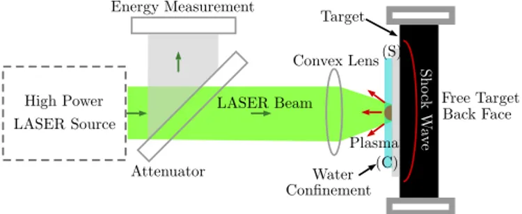
When a laser pulse of short duration and high power density reaches a target’s surface, the first few micrometers of the latter are transformed into intense plasma2which expands rapidly against the target’s surface (See Figure 1). Plasma
expansion release creates by reaction a shock wave into the target. The pressure generated by such shock can cover a range from MPa to GPa [12, 13, 14]. In order to drive signicant shock pressure, water confinement is generally used. The confinement slows down the plasma expansion and results in an increased ablation pressure (from 5 to 10 times higher compared to the direct irradiation) and a longer shock duration (from 2 to approximately 3 times longer) [15, 16]. Furthermore, a sacrificial layer can be interposed between the target’s surface and the confining medium in order to absorb the plasma induced thermal effects. Usually, an aluminum painting is used as sacrificial layer since laser-aluminum interaction is well documented [10].
1Laser intensity I(GW /cm2) is calculated using the laser beam energy E(J), the pulse duration ∆t(ns) and the focal surface S(cm2) as defined in
the equation below: I= E S×∆t
2Plasma is a hot ionized gas consisting of approximately equal numbers of positively charged ions and negatively charged electrons. The
characteristics of plasmas are significantly different from those of ordinary neutral gases so that plasmas are considered a distinct ”fourth state of matter”
Energy Measurement Convex Lens Attenuator Target LASER Beam (S) (C) High Power LASER Source Water Confinement Plasma Free Target Back Face S h o ck W av e
Figure 1: Schematic of laser-matter interaction in the case of laser shock
2.2
Shock wave propagation and damage generation
Two configurations of laser shock are distinguishable, according to whether only one side of the target is irradiated (one pulse shock configuration) or both sides of the target are irradiated (symmetrical laser shock configuration). 2.2.1 One pulse laser shock
Time 0 P e Position D Pressure pulse S1 R1 R2 S2 (a) Time 0 P e Position D Pressure pulse S1 R1 R2 S2 (b)
Figure 2: Schematic 1D Time/position diagram in the case of one pulse laser shock - two different pulse durations In the case of one pulse laser Shock (See figure 2), the incident shock wave (S1) created by plasma expansion propagates through the target’s thickness according to properties depending on the multilayer material characteristics and geometry [17]. When reaching the sample’s back face which is a zero acoustic impedance frontier, (S1) is reflected into a release wave (R2) propagating backward. Meanwhile, the material’s front face is unloaded at the end of the pressure pulse. This is also generating a release wave (R1) propagating from the front face to the back face. Depending on the material impedance and thickness, these two release waves (R1 and R2) can intersect inside the material’s thickness and lead to local high tensile stresses. If the induced tensile stresses are high enough, damage (D) can be created inside the material.
It is important to note that the pressure pulse duration is a crucial parameter because it is the one that influences the position of the tensile stress maximum (see figure 2). Thus, in the case of composite targets, if the aim is to localize tensile stresses close to a given interface, pulse duration is the parameter to be tuned. Furthermore, damage severity is directly related to the level of the induced tensile stresses itself linked to the incident laser beam energy. Thus, if the aim is to control damage severity, laser beam energy is the parameter to be monitored.
2.2.2 Symmetrical laser shock
In symmetrical laser shock configuration, both left (L) and right (R) sides of the target are irradiated (see figure 3). The incident shock wave (SL) created by plasma expansion, itself generated by the left pulse, propagates through the target’s thickness. When reaching the sample’s right face, (SL) is reflected into a release wave denoted by (R-SL). Similarly, the incident shock wave (SR) created by the right pulse is reflected into a release wave (R-SR) once it reaches the sample’s left face. The crossing of the two release waves (R-SL) and (R-SR) creates local high tensile stress which, if high enough, can result in damage (D-SHM). Meanwhile, the sample’s left face is unloaded at the end of the left pressure pulse. This is generating a release wave (RL) propagating from the left face to the right one. This also applies to the right face. The latter is unloaded at the end of the right pulse which is creating a release wave (RR)
propagating from the right face to the left face. The crossing of (RR) and (R-SR) can result in damage (DL) close to the left side of the sample in the case the induced tensile stresses by such crossing overpass the material’s damage threshold. Likewise, the intersection between (RL) and (R-SL) can result in damage (DR) close to the sample’s right face. Time Time Pressure Pressure 0 e L R
Left pulse Right pulse
DL DR D-SHM P SL RL SR RR R-SR R-SL (a) Time Time Pressure Pressure 0 e L R Left pulse Right pulse DL DR D-SHM P SL RL SR RR R-SR R-SL DO (Damage Offset) TD (Time Delay) (b)
Figure 3: Schematic 1D Time/position diagram in the case of symmetrical laser shock - zero vs non zero time delay In [10], Ecault et al. showed through numerical simulations that time delay between the two laser pulses influences the position of the tensile loading zones and hence the position of damage through the thickness of the irradiated material. This also can be seen in the time-position diagrams presented in figure 3. The right diagram (3a) illustrates the case of the symmetrical laser shock with zero time delay. If we focus only on the position of D-SHM, we can see that the latter occurs at the average sample’s depth. The left diagram (3b) presents the case where a non-zero delay denoted by (TD) is introduced between pulses. In this case, the position of D-SHM is shifted by a distance denoted by (DO). Theoretically, in a 1D approach that neglects the transmission/reflection phenomena, the product of time delay (TD) and speed of sound in the material (C) gives the offset in depth (DO) relative to the average sample’s depth.
DO= T D×C (1)
Thus if the aim is to localize tensile stresses close to a given interface, time delay is the parameter to be monitored while laser beams energies are the parameters to be tuned in order to control the induced damage severity. For SHM assessment purposes, it would be convenient to induce only D-SHM and control its depth and extent.
3
Experimental investigations
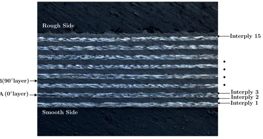
The samples considered in this work are CFRP laminates supplied by Aircelle/Safran. They are made of 16 unidirec-tional plies and have dimensions of 50× 50 × 2.2mm. The lay-up is of A-B-A-B (0°, 90°) type (see figure 4). Laser shocks were conducted using Gaia HP laser source of PIMM Hephaistos platform. It is a 2× 7J, 10ns laser source emitting at 532nm with a Gaussian temporal profile and a top hat spatial profile. We started by investigating the damage threshold of our samples when they are subject to only one laser pulse and when they are subject to symmetrical laser pulses. Then, two series of experiments were carried out to find out the effect of time delay as well as the effect of beams’ energies on the induced damage position and size respectively. Let A and B be the laser channels as shown in figure 5. A distance of 12.8cm separates the test sample from each lens which corresponds to a 6mm diameter irradia-tion spots. The laser irradiairradia-tions were performed in water confinement configurairradia-tion. Aluminum painting was used as sacrificial layer.
A (0◦layer) (90◦layer) B Interply 1Interply 2 b Interply 15 b b b Rough Side Smooth Side Interply 3
Figure 4: Cross-sectional microscopy of a test sample
Target
Convex lens Convex lens
Laser channel Laser channel
A
B
Beam splitter
Mirror Mirror
Mirror
Figure 5: Experimental set up
3.1
Research of damage threshold
In this paragraph, we investigate the damage threshold of our composite laminates when they are subject to only one laser pulse. This step is crucial because it will allow as to adequately tune our laser parameters in order to avoid near to surface damages (DL and DR in figure 3) while still having D-SHM. The samples were subject to increasing laser intensities. At each laser intensity, the irradiated sample was recovered from the experimental room and analyzed using an A-scan ultrasonic testing. The latter was carried out using a transducer emitting at 10MHz. A variable called echo observation takes the value of 0 when no damage echo is observed between the initial pulse and the back echo pulse, a value of 1 when a damage echo is clearly observed and a value between 0 and 1 when the damage echo is not clearly distinguished.
Similarly, we investigated the damage threshold of our CFRP laminates when they are subject to symmetrical laser pulses. Our aim consists always in finding the adequate parameters in order to avoid DL and DR while still having D-SHM.
3.2
Time delay effect
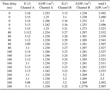
In order to study the effect of time delay, a first series of impacts was considered at constant beams energies, namely 50 % of channel A energy and 50 % of channel B energy, and various time delays. Time delays of 0ns, 80ns, 160nsand240ns were considered. Such choice of time delays was not arbitrary. As mentioned in equation 1 the product TD× C , where C is the speed of sound in the material, gives the damage offset in depth relative to the average sample’s depth. Hence, in the case of our material for which C is estimated to be equal to 1.7E− 3mm/ns, a time delay of 80ns for example will shift the damage position by 80× 1.7E − 3 = 0.136mm which corresponds to one ply thickness. More generally, a time delay of n× 80ns will shift the damage position by n × 80 × 1.7E − 3 = n × 0.136mm which corre-sponds to the thickness of n plies. Table 1 summarizes the energy in(J) and the intensity in (GW /cm2) of each laser
five times. Post-mortem analyses using A-scan ultrasonic testing were conducted in order to estimate damage position through the thickness of the impacted samples.
Table 1: Time delay effect at constant laser energy
Time delay E(J) I(GW /cm2) E(J) I(GW /cm2) total I
(ns) Channel A Channel A Channel B Channel B (GW /cm2)
0 3.16 1.253 3.12 1.238 2.492 0 3.15 1.25 3.1 1.230 2.480 0 3.14 1.246 3.16 1.253 2.5 0 3.13 1.242 3.16 1.253 2.496 0 3.15 1.25 3.21 1.273 2.523 80 3.112 1.234 3.27 1.297 2.532 80 3.12 1.238 3.28 1.301 2.539 80 3.12 1.238 3.29 1.305 2.543 80 3.09 1.226 3.23 1.281 2.507 80 3.1 1.230 3.27 1.297 2.527 160 3.14 1.246 3.23 1.281 2.527 160 3.14 1.246 3.24 1.285 2.531 160 3.12 1.238 3.24 1.285 2.523 160 3.1 1.230 3.23 1.281 2.511 160 3.13 1.242 3.23 1.281 2.523 240 3.13 1.242 3.23 1.281 2.523 240 3.1 1.230 3.2 1.269 2.5 240 3.1 1.230 3.2 1.269 2.5 240 3.08 1.222 3.2 1.269 2.492 240 3 .1 1.230 3.22 1.2778 2.507
3.3
Energy effect
In order to study the effect of laser beams energies, a second series of impacts was considered at constant time delay, namely 0ns, and various beams energies. The energies configurations that have been tested are: 20%, 40%, 60%, 60%, 80% and 100% of the energy of each channel. Table 2 summarizes the energy in(J) and the intensity in (GW /cm2)
of each channel while investigating the effect of laser beams energies. For repeatability analysis, note that each energy configuration was tested five times. Post-mortem analyses using A-scan ultrasonic testing were also conducted in order to estimate damage size.
Table 2: Energy effect at constant time delay
E E(J) I(GW /cm2) E(J) I(GW /cm2) total I
(%) Channel A Channel A Channel B Channel B (GW /cm2)
20 1.29 0.511 1.36 0.539 1.051 20 1.32 0.523 1.34 0.531 1.055 20 1.3 0.515 1.34 0.531 1.047 20 1.3 0.515 1.35 0.535 1.051 20 1.31 0.519 1.34 0.531 1.051 40 2.54 1.007 2.55 1.011 2.019 40 2.51 0.996 2.56 1.015 2.011 40 2.51 0.996 2.59 1.027 2.023 40 2.54 1.007 2.56 1.015 2.023 40 2.51 0.996 2.55 1.011 2.007 60 3.74 1.484 3.78 1.5 2.984 60 3.72 1.476 3.75 1.488 2.964 60 3.71 1.472 3.79 1.503 2.976 60 3.65 1.448 3.71 1.472 2.920 60 3.7 1.468 3.78 1.5 2.968 80 4.89 1.940 5.02 1.992 3.932 80 4.89 1.940 5.03 1.996 3.936 80 4.9 1.944 5.02 1.992 3.936 80 4.85 1.924 4.95 1.964 3.888 80 4.85 1.924 4.95 1.964 3.888 100 6.06 2.404 6.2 2.460 4.865 100 6.01 2.384 6.16 2.444 4.829 100 6.08 2.412 6.2 2.460 4.873 100 6.03 2.392 6.2 2.460 4.853 100 6.02 2.388 6.16 2.444 4.833
4
Results & Analysis
4.1
Research of damage threshold
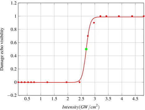
0.5 1 1.5 2 2.5 3 3.5 4 4.5 −0.2 0 0.2 0.4 0.6 0.8 1 1.2 Intensity(GW /cm2) Damage echo visibility
Figure 6 illustrates a sigmoid function fitted to the data obtained while searching for the damage threshold of our test samples when they are subject to one laser pulse (T hreshone−pulse). If one assumes that the latter coincides with
the 50% point after sigmoid fitting, then T hreshone−pulsecorresponds to a laser intensity of 2.7GW /cm2.
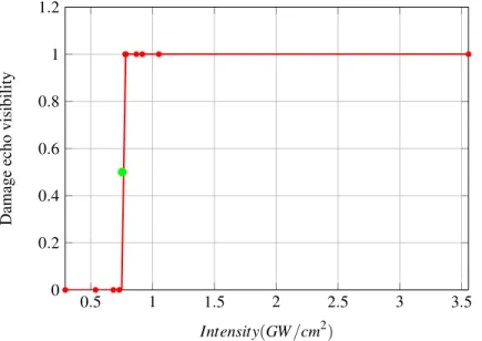
0.5 1 1.5 2 2.5 3 3.5 0 0.2 0.4 0.6 0.8 1 1.2 Intensity(GW /cm2) Damage echo visibility
Figure 7: Damage threshold in the case of symmetric pulses
Figure 7 shows a sigmoid curve fitted to the data obtained while investigating the damage threshold of our test samples when they are subject to symmetrical laser pulses (T hreshsym−pulses). If one assumes that the latter coincides
with the 50% point after sigmoid fitting, then T hreshsym−pulsescorresponds to a laser intensity of 0.76GW /cm2.
If we focus on the values of channels A intensity as well as channel B intensity in tables 1 and 2, we draw attention that those intensity values do not overpass our test samples damage threshold under one pulse laser shock while the total intensity (6th column in tables 1 and 2) overpasses the test samples damage threshold under symmetrical laser
pulses. As a consequence, it is expected that near to surface damages, that is DL and DR (Figure 3), will not occur while still having D-SHM.
4.2
Time delay effect
−50 0 50 100 150 200 250 1.1 1.2 1.3 1.4 1.5 y= 0.00135x + 1.148, R2= 0.96877
Time delay between laser pulses (ns)
Damage
depth
(mm)
Theory (Eq (1)) Linear regression fit Experimental (errorbar)
Figure 8 depicts the theoretical as well as the experimental curves of damage position as a function of time delay. The experimental results thus obtained show that, as expected, there is an evident relationship between time delay and through thickness damage position. Furthermore, there is a good match between theoretical and experimental results.
4.3
Energy effect
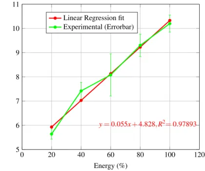
0 20 40 60 80 100 120 5 6 7 8 9 10 11 y= 0.055x + 4.828, R2= 0.97893 Energy (%) Damage size (mm)Linear Regression fit Experimental (Errorbar)
Figure 9: Energy effect at constant time delay
From figure 9 , it can be seen that laser channels energies have an evident relationship with the induced damage size . An increasing value of the laser channels energies results in an increasing damage size. We also draw attention to the maximum damage size obtained. The latter is around 10mm. In order to get damage sizes of higher values for our future SHM applications, the idea is to combine laser shock induced delaminations by multiple impacts. This idea will be further investigated in a future paper.
5
Conclusion & future work
In this paper we investigate Laser Shock Wave Technique as an innovative way to calibrate damage in CFRP composite laminates. The method has been applied to various fields such as LASAT. To our knowledge, this is the first study to deal with its application to damage calibration. The findings of our research are quite convincing, and thus the following conclusions can be drawn:
• The symmetrical laser shock is a good alternative to conventional damage generation techniques thus opening new perspectives for SHM applications.
• An adequate tuning of laser parameters, namely laser energy (intensity) and time delay, allows a good monitoring of damage size and through thickness damage position respectively.
In this study, A-scan ultrasonic testing was selected for post-mortem analyses. Future analyses will include C-scan ultrasonic testing, tomography, cross section microscopy and penetrant testing. Further study of the multiple impacts issue is still required. On the basis of the promising findings presented in this paper, work on the remaining issues is continuing and will be presented in future papers.
Acknowledgement
The authors would like to thank Yann Rouchausse, member of the Laser shock team at PIMM laboratory for his support during the experimental trials. Also to the members of R&T composites laboratory of the Materials and Processes Department of Aircelle Company for their help during the post-mortem analyses presented in the research herein.
References
[1] Charles R Farrar and Keith Worden. An introduction to structural health monitoring. Philosophical transactions of the Royal Society, 365(December 2006):303–15, 2007.
[2] Anders Rytter. Vibrational Based Inspection of Civil Engineering Structures. PhD thesis, Aalborg University, 1993.
[3] Dae-un Sung, Chun-gon Kim, and Chang-sun Hong. Monitoring of impact damages in composite laminates using wavelet transform. Composites Part B: Engineering, 33:35–43, 2002.
[4] M.J. Santos, J.B. Santos, a.M. Amaro, and M.a. Neto. Low velocity impact damage evaluation in fiber glass composite plates using PZT sensors. Composites Part B: Engineering, 55:269–276, 2013.
[5] G. Santoni-Bottai and V. Giurgiutiu. Damage detection at cryogenic temperatures in composites using piezoelec-tric wafer active sensors. Structural Health Monitoring, 11:510–525, 2012.
[6] Zhenhua Tian, Lingyu Yu, Cara Leckey, and Jeffrey Seebo. Guided wave imaging for detection and evaluation of impact-induced delamination in composites. Smart Materials and Structures, 24(10):105019, 2015.
[7] L. Berthe, M. Arrigoni, M. Boustie, J. P. Cuq-Lelandais, C. Broussillou, G. Fabre, M. Jeandin, V. Guipont, and M. Nivard. State-of-the-art laser adhesion test (LASAT). Nondestructive Testing and Evaluation, 26(3-4):303– 317, September 2011.
[8] R Ecault, M Boustie, L Berthe, F Touchard, H Voillaume, B Campagne, and D Loison. Development of a laser shock wave adhesion test for the detection of weak composite bonds. In International Symposium on NDT in Aerospace, Singapore, 2013.
[9] Romain Ecault, Michel Boustie, Fabienne Touchard, Fr´ed´eric Pons, Laurent Berthe, Laurence Chocinski-Arnault, Bastien Ehrhart, and Clemens Bockenheimer. A study of composite material damage induced by laser shock waves. Composites Part A: Applied Science and Manufacturing, 53:54–64, 2013.
[10] Romain Ecault. Experimental and numerical investigations on the dynamic behaviour of aeronautic composites under laser shock - Optimization of a shock wave adhesion test for bonded composites. M´ecanique des mat´eriaux, Ecole Nationale Sup´erieure de M´ecanique et d’A´erotechnique - ENSMA, 2013.
[11] Bastien Ehrhart, Romain Ecault, Fabienne Touchard, Michel Boustie, Laurent Berthe, Clemens Bockenheimer, and Bernd Valeske. Development of a laser shock adhesion test for the assessment of weak adhesive bonded CFRP structures. International Journal of Adhesion and Adhesives, 52:57–65, 2014.
[12] J. W Trainor, R. J; Graboske, H. C ; Long, K. S; Shaner. Application of high power lasers to equation of state research at ultrahigh pressure. Technical report, Lawrence Livermore Laboratory, University of California Livermore, California, 1978.
[13] Michel Arrigoni, Jean-paul Cuq Lelandais, Michel Boustie, and Elise Gay. An Industrial Challenge Based on the Wave Propagation : the Shock Adhesion Test. In Wave Propagation, pages 605–633. Academy Publish, 2014. [14] Elise Gay. Comportement de composites sous choc induit par laser : d´eveloppement de l’essai d’adh´erence par
choc des assemblages de composites coll´es. Sciences des m´etiers de l’ing´enieur, Ecole nationale sup´erieure d’arts et m´etiers - Ensam ParisTech, 2011.
[15] L Berthe, R Fabbro, P Peyre, L Tollier, and E Bartnicki. Shock waves from a water-confined laser-generated plasma. Journal of Applied Physics, 82(1997):2826–2832, 1997.
[16] R. Fabbro, J. Fournier, P. Ballard, D. Devaux, and J. Virmont. Physical study of laser-produced plasma in confined geometry. Journal of Applied Physics, 68(1990):775–784, 1990.
[17] R. Ecault, M. Boustie, L. Berthe, and F. Touchard. Laser shock waves: A way to test and damage composite materials for aeronautic applications. AIP Conference Proceedings, 126:126–137, 2012.
![Figure 3: Schematic 1D Time/position diagram in the case of symmetrical laser shock - zero vs non zero time delay In [10], Ecault et al](https://thumb-eu.123doks.com/thumbv2/123doknet/7445438.220926/5.918.120.817.194.412/figure-schematic-time-position-diagram-symmetrical-laser-ecault.webp)