Science Arts & Métiers (SAM)
is an open access repository that collects the work of Arts et Métiers Institute of
Technology researchers and makes it freely available over the web where possible.
This is an author-deposited version published in:
https://sam.ensam.eu
Handle ID: .
http://hdl.handle.net/10985/8964
To cite this version :
François MALBURET, Tomasz KRYSINSKI, Jean-Paul NAUZIN - Lightweight design: mass in
transit - Showcase 2013 p.4 - 2012
Any correspondence concerning this service should be sent to the repository
Administrator :
[email protected]
lightweight design
.com•Annual Showcase 2013lightweight design
.com•Annual Showcase 201345
44
The new worldwide accreditation cycle, the Worldwide Harmonized Light-duty Test Procedures (WLTP), will replace the current European cycle, the New European Driving Cycle (NEDC), as of 2020. It should be more representative of customers’ actual use of vehicles. In particular, it will include more violent acceleration/ deceleration phases and higher average speeds than the current cycle, with a view to bringing the measured consumption closer to that experienced by the customer.
The implementation of this new cycle will force automobile manufacturers to completely reassess the various impacts related to consumption. While the influence of some major factors in the NEDC cycle (downsizing or electrification of components, etc.) will be more limited in the WLTP cycle, the impact of factors such as weight will increase.
Figure 1 shows that the weight of vehicles has increased substantially over the past 15 years, a trend that is common to all manufacturers.
This change is due to a number of factors which, when listed in order of importance, are as follows: 40% due to passive safety; 15% due to the
development of vehicle equipment; 15% due to improved soundproofing, as well as safety-related structural reinforcements; increased vehicle size; pollution reduction systems; and increased weight of other components such as suspension systems, brakes and gearbox systems, in order to offset the increased loads on vehicle axles.
The impact of weight on consumption has been shown in a statistical study carried out on 33 recent diesel vehicles. It roughly indicates that an additional consumption of approximately 0.5 l/100km can be expected per 100kg of extra weight. In practice, this is far more complex, as consumption depends on more than weight alone. Factors related to the vehicle’s aerodynamic drag as well as its expected performance, which determines the size of the powertrain, must also be factored in.
Reducing consumption involves much more than engine development. All consumption sources – including tire rolling resistance and vehicle weight – as well as their reduction potentials, need to be assessed through a systematic, physical approach. It is also very important to account for the way in which the various actions are interconnected in order to achieve the best result.
Designing a lightweight vehicle
There are many ways to reduce
vehicle CO2 emissions by reducing weight: through direct effects (e.g. reducing the weight of components by using lighter materials) and indirect effects (virtuous cycle generated by initial weight savings).
In terms of direct effects, understanding the way in which weight and architecture are interconnected is key when it comes to lightweight vehicle design.
Vehicles are comprised of ‘hard’ items such as the engine and brakes, which constitute a mostly non-compressible weight when changing the vehicle’s dimensions. Therefore, modifying the vehicle’s dimensions will not have a significant impact on the weight of its components.
Put simply, on a constant equipment basis, the variation in weight from one vehicle to another is primarily related to the variation in the vehicle’s dimensions. This is referred to as downsizing, or architecture fine-tuning, which ensures ample interior space by reducing the dimensions that are relevant for weight reduction purposes. To do this, the vehicle’s weight is broken down into five parts, as shown in Figure 2. The statistical data on the same segment provides an average data for each segment, which varies according to the technologies used.
The value of these gradients is empirical and is used for pre-project calculations.
Mass in transit
TOMASZ KRYSINSKI AND JEAN-PAUL NAUZIN (PSA PEUGEOT CITROËN) AND
FRANÇOIS MALBURET (ARTS ET MÉTIERS PARISTECH) OFFER SOME FACTORS FOR
CONSIDERATION WHEN DESIGNING A LIGHTWEIGHT VEHICLE
“Decreasing the
vehicle’s weight
directly decreases
the energy
that has to
be dissipated
proportionately
and therefore
makes it possible
to use smaller
brakes”
Rolling resistanceTires play a complex role in reducing fuel consumption, as they affect rolling resistance, aerodynamics, and the general architecture (Figure 3).
Rolling resistance is directly related to the wheels’ tire geometrical data. The larger a vehicle’s wheels are, the lower its friction coefficient is.
With the f function dependent on the size of the tire and the technology used
The design of the tread layer can reduce the aerodynamic drag by a few percent. The design of the tread layer and the outer sidewall can reduce the air surface and optimize the airflow around the tire. When modeling in the preliminary vehicle design phase to define the impact of architecture on consumption, the effects of the aerodynamic pressure zones around the wheel area are neglected.
More generally, reducing consumption involves finding a compromise between the various factors related to aerodynamics, rolling resistance, and weight.
For example, increasing the wheels’ diameter increases the vehicle’s weight while maintaining the same interior space; reduces the rolling resistance coefficient; and increases the aerodynamic drag.
Overall, increasing the wheels’ diameter increases the vehicle’s consumption.
New materials and technologies
Once the vehicle’s architecture has
been determined, weight can also be reduced by introducing new materials and integrating components and functions in the same system. Figure 4 shows the weight proportions of the various subsystems of a vehicle.
A classical way to reduce vehicle weight involves the use of lighter materials such as aluminum, magnesium, plastic, or carbon fiber, as well as steel alloys. As mentioned above, reducing a vehicle’s weight by 100kg results in savings of 0.5 l/100km. However, the large-scale distribution of these lightweight materials is not developed widely enough and is still too limited to high-end cars.
The use of new technologies can contribute to reducing vehicle weight directly. This can be the case by combining functions, optimizing components, developing intelligent solutions, or integrating functions such as third-generation bearings, one-piece parts, future mechatronics systems, or using nanotechnologies over the longer term. Given the large number of sensors and electronics in passenger vehicles, nanotechnologies have a strong potential to miniaturize and transfer data. A major hurdle is producing these components and integrating them into production lines, as well as recycling them.
Virtuous cycles
Following an initial weight-reduction phase by optimizing the architecture and choice of materials, a second weight-reduction phase can be obtained by assessing the effects of the first weight-reduction phase.
FIGURE 3: THE TIRE’S INFLUENCE IN SAVING VEHICLE WEIGHT
FIGURE 4: VEHICLE WEIGHT SUBSYSTEM CONTRIBUTIONS
FIGURE 5: LOAD TRANSFER DURING BRAKING
The first weight-reduction phase has effects on subsystems’ loads. Each subsystem can then be optimized, thereby further reducing the weight of the overall structure.
Reducing a vehicle’s weight and the inter-structure forces also has an effect on the vehicle’s performance, which can be broken down into three main groups – impact, rigidity, and resistance. Each of these groups is affected by a set of performances that has a bearing on weight.
These performances need to be taken into account when optimizing each subsystem. This will often result in finding a compromise.
The downsizing of brake system components is one example of a virtuous effect. The required braking power at time t is expressed by:
If we assume that the power losses related to rolling and aerodynamic forces are insignificant, as well as the engine braking action, then we can approximate the braking power output by:
FIGURE 1: CHANGE IN VEHICLE WEIGHT OVER THE PAST 30 YEARS
FIGURE 2: SIMPLIFIED MODELING OF THE VEHICLE’S WEIGHT BASED ON GEOMETRIC PARAMETERS
1
2
3 4
.com•Annual Showcase 2013 .com•Annual Showcase 2013
46
lightweight design
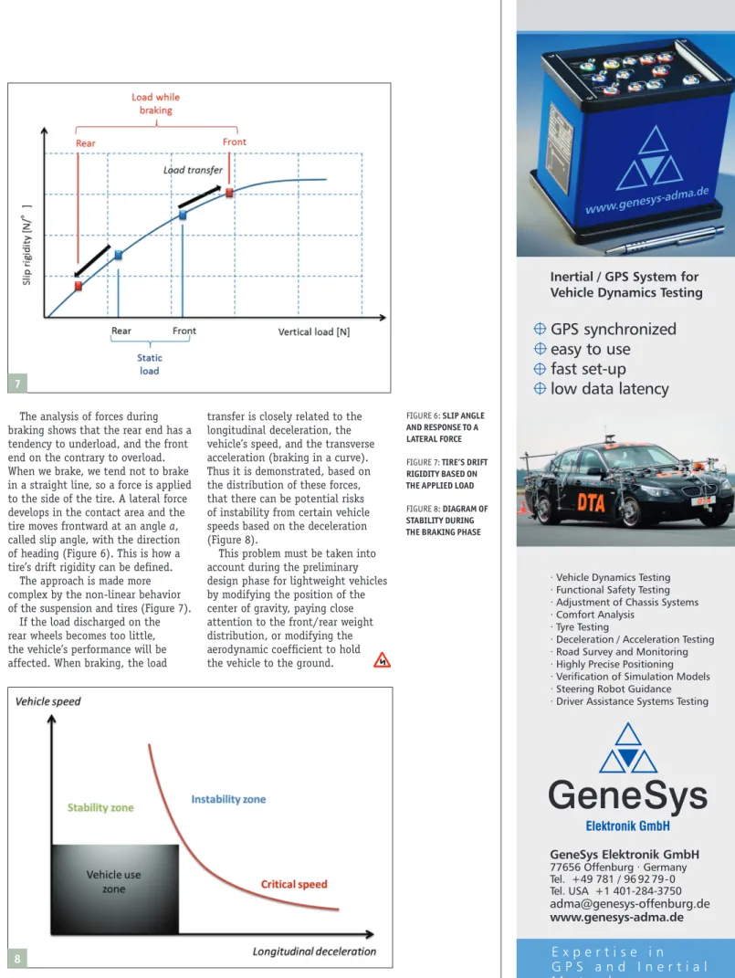
The analysis of forces during braking shows that the rear end has a tendency to underload, and the front end on the contrary to overload. When we brake, we tend not to brake in a straight line, so a force is applied to the side of the tire. A lateral force develops in the contact area and the tire moves frontward at an angle a, called slip angle, with the direction of heading (Figure 6). This is how a tire’s drift rigidity can be defined.
The approach is made more complex by the non-linear behavior of the suspension and tires (Figure 7).
If the load discharged on the rear wheels becomes too little, the vehicle’s performance will be affected. When braking, the load
transfer is closely related to the longitudinal deceleration, the vehicle’s speed, and the transverse acceleration (braking in a curve). Thus it is demonstrated, based on the distribution of these forces, that there can be potential risks of instability from certain vehicle speeds based on the deceleration (Figure 8).
This problem must be taken into account during the preliminary design phase for lightweight vehicles by modifying the position of the center of gravity, paying close attention to the front/rear weight distribution, or modifying the aerodynamic coefficient to hold the vehicle to the ground.
Material world
Magneti Marelli has been working on prototype composite suspension components for some years now, writesGraham Heeps. Having realized a mass- production-feasible, crash-safe, reinforced composite suspension arm that reduces component weight from around 1.5kg for an ultralight steel version to no more than 0.85kg, the firm’s next target is to investigate the use of basalt- or glass-fiber to bring the cost down. The carbon-fiber version comes in at around five times the cost of the steel alternative.
“In the next few years composite materials will play a very important role in automotive structural and safety components,” says Piero Monchiero, suspension R&D manager at Magneti Marelli. “We are starting to understand which are the right technologies and which will be the right technical solutions to develop our parts and components with this kind of material.
“We started with carbon fiber but along the way we’ve come to understand that it’s probably not necessary. Basalt and glass-fiber will probably be good enough for conventional vehicles. The cost of glass and basalt is very acceptable but it is necessary to develop the technology a little bit to verify their reliability over the long term. Our parts have a long life, 15-20 years, so we have to verify their safety. But I think that we are near to having good, light materials [for suspension parts] using composites.”
Magneti Marelli is studying the potential for composite knuckles and is also working on a front subframe made from a composite material. The latter probably won’t need
reinforcement from a ductile material, according to Monchiero.
“For components like the arms, which you have to sacrifice under crash conditions, yes it’s necessary,” he says. “But according to our first level of verification for subframes, it’s probably not. These components have to be stiffer, more
resistant, so it probably isn’t necessary to use a hybrid [material] solution.”
The rapid pace of development in this area provides a real opportunity for innovation, Monchiero believes. “The base plastics materials are being developed very quickly. I see that when I talk to suppliers of plastic materials over the course of a few months, they tell me that they now have new materials available. For example, when we started work on the composite arm, we used a thermoplastic material because at the time, this was the plastic material with the fastest curing time. But now thermoset materials are also achieving very short cure times, meaning that each operation needs less than one minute rather than the 10 or 15 minutes of before. We had to change to using thermoset material because the technology had developed so much.”
The energy dissipated over braking time T is given by the equation:
For example, a 1,400kg vehicle moving at 120km/h has to dissipate 776kJ of energy, which gives an average power of 141kW for a braking time of 5.5 seconds (deceleration of 0.6g). This energy that has to be dissipated has an impact on the force that has to be created inside the brakes. Decreasing the vehicle’s weight directly decreases the energy that has to be dissipated proportionately and therefore makes it possible to use smaller brakes. The relationship between the energy dissipated and the size of brakes (and therefore their weight) is not linear or continuous. For example, changing
from 283 x 26 front disc brakes with caliper 60 to 266 x 22 front discs with caliper 57, related to a 150kg reduction in gross vehicle weight, saves 5.7kg for vehicles in the C segment.
Weight reduction measures such as this can create problems, however, as the example of high-speed braking shows. A vehicle at a standstill has an initial load distribution on the various wheels. When rolling, and especially in braking situations, the load on each tire will vary. This results in an additive or subtractive force based on the stress placed on the vehicle. A number of parameters influence this weight transfer including the vehicle’s weight, the position of the center of gravity, the wheelbase, the width of the road, the downforces, and the tires’ performance.
A D M A
E x p e r t i s e i n
G P S a n d I n e r t i a l
M e t r o l o g y
Inertial / GPS System for
Vehicle Dynamics Testing
GPS synchronized
easy to use
fast set-up
low data latency
· Vehicle Dynamics Testing · Functional Safety Testing · Adjustment of Chassis Systems · Comfort Analysis
· Tyre Testing
· Deceleration / Acceleration Testing · Road Survey and Monitoring · Highly Precise Positioning · Verification of Simulation Models · Steering Robot Guidance · Driver Assistance Systems Testing
GeneSys Elektronik GmbH www.genesys-adma.de 77656 Offenburg · Germany Tel. +49 781 / 96 92 79 -0 Tel. USA +1 401-284-3750 [email protected]
GeneSys
Elektronik GmbH
FIGURE 6: SLIP ANGLE AND RESPONSE TO A LATERAL FORCE
FIGURE 7: TIRE’S DRIFT RIGIDITY BASED ON THE APPLIED LOAD
FIGURE 8: DIAGRAM OF STABILITY DURING THE BRAKING PHASE
6
7