RESEARCH OUTPUTS / RÉSULTATS DE RECHERCHE
Author(s) - Auteur(s) :
Publication date - Date de publication :
Permanent link - Permalien :
Rights / License - Licence de droit d’auteur :
Institutional Repository - Research Portal
Dépôt Institutionnel - Portail de la Recherche
researchportal.unamur.be
University of Namur
Methodology and CASE tools for the Development of Federated Databases
Hainaut, Jean-Luc; Thiran, Philippe; Hick, Jean-Marc; Bodart, Stephane; Deflorenne, Arnaud
Published in:
International Journal of Cooperative Information Systems
Publication date:
1999
Document Version
Peer reviewed version
Link to publication
Citation for pulished version (HARVARD):
Hainaut, J-L, Thiran, P, Hick, J-M, Bodart, S & Deflorenne, A 1999, 'Methodology and CASE tools for the Development of Federated Databases', International Journal of Cooperative Information Systems, vol. 8(2-3), pp. 169-194. <http://www.worldscinet.com/journals/ijcis/ijcis.shtml>
General rights
Copyright and moral rights for the publications made accessible in the public portal are retained by the authors and/or other copyright owners and it is a condition of accessing publications that users recognise and abide by the legal requirements associated with these rights. • Users may download and print one copy of any publication from the public portal for the purpose of private study or research. • You may not further distribute the material or use it for any profit-making activity or commercial gain
• You may freely distribute the URL identifying the publication in the public portal ? Take down policy
If you believe that this document breaches copyright please contact us providing details, and we will remove access to the work immediately and investigate your claim.
METHODOLOGY AND CASE TOOLS FOR THE DEVELOPMENT OF FEDERATED DATABASES*
J-L. HAINAUT, P. THIRAN, J-M. HICK, S. BODART, A. DEFLORENNE
University of Namur, Institut d’Informatique, rue Grandgagnage, 21, 5000 Namur, Belgium
Due to the current technological and economical context, there is an increasing need for cooperating information systems based on federated databases. Though the technical issues of these architectures have been studied for long, the way to build them has not triggered as much effort. This paper describes a general architecture, a methodology and a CASE environment intended to address the problem of providing users and programmers with an abstract interface to independent heterogeneous and distributed databases. The architecture comprises a hierarchy of mediators and a repository that dynamically transform actual data into a virtual homogeneous database and allow client applications to query it. The InterDB approach provides a complete methodology to define this architecture, including schema recovery through reverse engineering, database integration and mapping building. The methodology is supported by the DB-MAIN CASE tool that helps developers generate the mediators and their repository.
Keywords: federated database, DBMS independence, wrapper, methodology, CASE tool
1. Introduction
Most large organizations maintain their data in many distinct independent databases that have been developed at different times on different platforms and DMS (Data Management Systems).
The new economic challenges force enterprises to integrate their functions and therefore their information systems including the databases they are based on. In most cases, these databases cannot be replaced with a unique system, nor even reengineered due to the high financial and organizational costs of such a restructuring. Hence the need for interoperation frameworks that allow the database to be accessed by users and application programs as if they were a unique homogeneous and consistent database, through an architecture called federated databases.1
Accessing and managing data from such heterogeneous databases pose complex problems that can be classified into platform, DMS, location and semantics level.2,3 The
platform level copes with the fact that databases reside on different brands of hardware, under different operating systems, and interacting through various network protocols. Leveling these differences leads to platform independence. DMS level independence allows programmers to ignore the technical detail of data implementation in a definite
family of models or among different data models. Location independence isolates the user from knowing where the data reside. Finally, semantic level independence solves the problem of multiple, replicated and conflicting representations of similar facts.
Current technologies such as de facto standards (e.g., ODBC and JDBC), or formal body proposals (e.g., CORBA), now ensure a high level of platform independence at a reasonable cost4, so that this level can be ignored from now on. DMS level independence
is effective for some families of DBMSs (e.g., through ODBC or JDBC for RDBMSs), but the general problem still is unsolved when several DMS models have to cooperate. Location independence is addressed either by specific DBMSs (such as distributed RDBMSs) or through distributed object managers such as CORBA-compliant middleware products.5 Despite much effort spent by the scientific community, semantic independence still is an open and largely unsolved problem except in simple situations.
This paper describes a general architecture, a methodology and a CASE environment intended to address the problem of providing users and programmers with an abstract interface to independent, heterogeneous and distributed databases. These components are being developed as part of the InterDB project. The paper is organized as follows. Section 2 develops a small case study that allows us to identify some of the main problems to be solved. Section 3 presents the main aspects of the InterDB architecture for federated databases. Section 4 proposes a general methodology that helps developers build the components of the architecture. In section 5, we discuss the role of CASE technology to support that methodology. Section 6 concludes the paper.
2. Problem statement
The general architecture of federated databases has been described in, e.g., references.2,6
It consists of a hierarchy of data descriptions that ensure independence according to different dimensions of heterogeneity: location, technology and semantics for example. According to this framework, each local database is described by its own local schema, from which a subset, called export schema, is extracted. The latter are merged into the global schema. Each application interacts with the local data through a view derived from this global schema. The mappings between adjacent levels ensure the various kinds of independence. The global schema, and generally the export schemas, are expressed in some kind of pivot data model which is independent of the underlying technologies (except when the latter all belong to the same family of models).
In this section we develop a small example that illustrates the problems we intend to address in the InterDB approach.
The database integration example comprises two independent heterogeneous databases both describing aspects of a bookshop, that are required to interoperate. The first one is made up of two COBOL files and the second one includes two relational tables. The integration process will be carried out in three steps, namely conceptual
schema recovery, conceptual integration and mapping definition. 2.1. Conceptual schema recovery
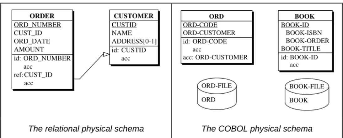
By analyzing the COBOL programs and SQL DDL scripts, we can extract the local physical schema (LPS) of each database. Fig. 1 shows the extracted schemas according to a common abstract physical model.
ORDER ORD_NUMBER CUST_ID ORD_DATE AMOUNT id: ORD_NUMBER acc ref: CUST_ID acc CUSTOMER CUSTID ORD ORD-CODE BOOK BOOK-ID NAME ADDRESS[0-1] id: CUSTID acc ORD-CUSTOMER id: ORD-CODE acc acc: ORD-CUSTOMER BOOK-ISBN BOOK-ORDER BOOK-TITLE id: BOOK-ID acc ORD-FILE ORD BOOK-FILE BOOK
The relational physical schema The COBOL physical schema
Fig. 1. The local physical schemas. The relational database (left) comprises two tables, namely CUSTOMER and ORDER. ADDRESS is an optional column (cardinality [0-1]). The other columns are mandatory (default cardinality [1-1], not displayed). Unique keys are represented by the id(entifier) construct, foreign keys by the
ref(erence) construct and indexes by the acc(ess key) construct. The COBOL database (right) is made of two
files and two record types (ORD and BOOK). BOOK-ID is a compound field and ORD-CUSTOMER is a non-unique alternate record key.
Based on the analysis of declarative code fragments or data dictionary contents, this process is fairly straightforward. However, it recovers explicit constructs only, ignoring all the implicit structures and constraints that may be buried in the procedural code of the programs or of the user interface. Hence, the need for a refinement process that cleans the physical schema and enriches it with implicit constraints elicited by such techniques as program analysis and data analysis. The schemas are refined through in-depth inspection of the way in which the COBOL programs and SQL DML statements use and manage the data in order to detect the record structures left undeclared in the program sources. Moreover, names have been reworked (meaningless prefix removed) and physical constructs are discarded (e.g., files and access keys). We therefore obtain the local logical schemas (LLS) of Fig. 2, that make two hidden constraints explicit, namely a foreign key and a functional dependency in the COBOL database. They express the data structures in a form that is close to the DMS model, enriched with semantic constraints.
The next phase consists in interpreting the logical structures by extracting their underlying semantics. The resulting conceptual schemas are expressed in a variant of the Entity-relationship model (Fig. 3).
ORDER ORD_NUMBER CUST_ID ORD_DATE AMOUNT ref: CUST_ID CUSTOMER CUSTID ORD ORD-CODE BOOK ISBN NAME ADDRESS[0-1] id: CUSTID CUSTOMER id: ORD-CODE ORDER TITLE id: ISBN ORDER ref: ORDER id: ORD_NUMBER
The relational logical schema The COBOL logical schema
Fig. 2. The local logical schemas of the relational database (left) and of the COBOL files (right). We observe the elicitation of an implicit foreign key and of a functional dependency in the COBOL database. The purely physical objects have been removed and names have been reworked.
1-1 places 0-N ORDER OrdNumber OrdDate Amount id: OrdNumber CUSTOMER Custid Name Address[0-1] id: Custid ORD Ord-code BOOK ISBN references 0-N 0-N Title id: ISBN Customer id: Ord-code
The relational conceptual schema The COBOL conceptual schema
Fig. 3. The local conceptual schemas (LCS) of the relational database (left) and of the COBOL files (right). The relational foreign keys have been transformed into relationship types. The BOOK record type has been normalized by splitting it into BOOK and REFERENCE, the latter being transformed into a many-to-many relationship type.
2.2. Conceptual integration
The global schema must include the semantics of these two local schemas. ORD and ORDER entity types appear to be similar. Usual heuristics in schema integration suggest that they may represent the same application domain entity sets or that one represents a subset of the population denoted by the other one. Data analysis, i.e., examination of actual instances of the physical data types shows that all the ORD.Ord-code values are in the ORDER.OrdNumber value set. Therefore, this similarity has to be interpreted as a supertype/subtype relation: ORD (renamed BOOK-ORDER) is made a subtype of ORDER. Besides this reasoning, the integration process is fairly standard. Hence the schema of Fig. 4.
2.3. Mapping definition
Once the global schema has been built, we have to state how global retrieval and update queries can be mapped onto physical data. In the processes above, the transitions between two schema levels can be expressed as formal transformations, such as
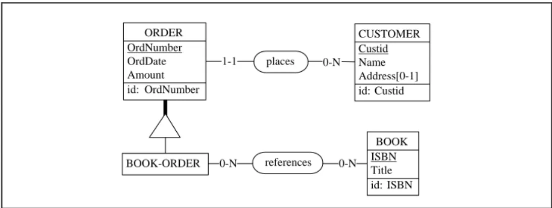
ORDER OrdNumber OrdDate Amount id: OrdNumber CUSTOMER Custid 1-1 places 0-N 0-N references 0-N Name Address[0-1] id: Custid BOOK ISBN BOOK-ORDER Title id: ISBN
Fig. 4. The global conceptual schema (GCS) resulting from the integration of the local schemas of Fig. 3.
The local physical/conceptual mappings can then be constructed by interpreting the reverse engineering transformations as two-way data conversion functions. Global/local mappings are based on the conceptual integration process. These mappings can be used to decompose global queries into local queries, and local data into global data. For instance, the following global conceptual query, that asks for the customers that have placed an order for a definite book,
select C.Custid,C.Name
from BOOK B,BOOK-ORDER O,CUSTOMER C where B.ISBN = '2-02-025247-3' and O references B and C places O
will be broken down into two local conceptual queries to be processed by the local database systems:
insert into TMP-O1(OrdCode) select O.Ord-code
from BOOK B,ORD O
where B.ISBN = '2-02-025247-3' and O references B
insert into TMP-03(Custid,Name) select C.Custid,C.Name
from ORDER O,CUSTOMER C, TMP-01 T where O.OrdNumber = T.OrdCode and C places O
Each of these queries is, in turn, translated into logical and physical queries that can be executed by the local DBMS. Conversely, the extracted data are transformed to make them comply with the local logical and conceptual schemas. Finally, the local conceptual data are integrated to form the global conceptual result.
Despite its small size, this example emphasizes some difficulties of database integration. The problem is especially complex when old, ill-designed and poorly documented applications are addressed. Hence the need for methodological and CASE support that will be discussed in this paper.
3. Architecture
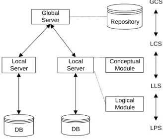
The InterDB architecture, shown in Fig. 5, is close to standard proposals (e.g., reference2). It comprises a hierarchy of mediators, namely the local servers dedicated to each database and a global server based on the global conceptual schema (GCS). These mediators dynamically transform global conceptual queries into local physical queries, and, conversely, transform actual data into a virtual homogeneous database. To simplify the discussion, export and view schemas have been ignored.
Global Server Local Server Local Server Conceptual Module DB DB GCS LCS LLS LPS Repository Logical Module
Fig. 5. The InterDB architecture of a federated database.
3.1 Local servers
The local server is in charge of managing the conceptual/physical conversion of each local database. It comprises two components, namely the logical module and the conceptual module. Though they can be implemented as a unique software component, they will be described distinctly.
A logical module hides the syntactic idiosyncrasies and the technical details of the DMS of a given model family. In addition, it makes the implicit constructs and constraints explicitly available. For instance, relational databases and flat COBOL files appear as similar logical structures. A logical module dynamically transforms queries (top-down) and data (bottom-up) between this logical model and the actual physical model. In particular, it emulates implicit constructs such as foreign keys in COBOL files or multivalued fields in relational databases.
All logical modules offer a common interface and present the physical data according to a common data model called the generic logical model. This model encompasses not only the current and legacy technologies (RDB, standard files, CODASYL, IMS, etc.), but also emerging ones, such as object-oriented models (ODMG).
A conceptual module provides a conceptual view of a local logical database. It hides the specific aspects of a family of models as well as the technical and optimization-dependent constructs of the actual database.
To summarize, each local server appears as a conceptual database manager that offers a unique abstract interface to application programs. It can translate local client queries into physical DML primitives (COBOL file primitives, SQL, DBTG DML, etc.). It can also compose physical data to form conceptual data aggregates requested by client applications. For performance reasons, we have decided to develop the local servers as program components dedicated to a local database. In particular, the logical/physical and conceptual/logical mapping rules are hardcoded in the modules rather than interpreted from mapping tables. To illustrate the translation mechanism, the local conceptual query
insert into TMP-03(Custid,Name) select C.Custid,C.Name
from ORDER O,CUSTOMER C, TMP-01 T where O.OrdNumber = T.OrdCode and C places O
will be translated by the local server into the physical query insert into TMP-03(Custid,Name)
select C.CUSTID,C.NAME
from ORDER O,CUSTOMER C, TMP-01 T where O.ORD_NUMBER = T.OrdCode and O.CUST_ID = C.CUSTID
This translation is based on the transformations (considered the reverse way) used to produce the conceptual schema (Fig. 3) from the physical one (Fig. 1), such as
FK-to-relationship-type and name-conversion.
The concept of local server, or mediator7, is very close to that of wrapper, which
encapsulates a legacy component in such a way that it can be manipulated as an object, and integrated into a larger system.8
3.2 The global server
The global server offers a conceptual interface based on the GCS. It processes the global queries, that is, queries addressing the data independently of their distribution across the different sites. For flexibility reasons, the module is based on a repository that describes the global conceptual schema, the local conceptual schema of each local server, its location, and the relationships between local and global schemas. Information concerning data replication, semantic conflicts and data heterogeneity allows the server to interpret and distribute the global queries, and to collect and integrate the results sent back by the local servers.
3.3 Heterogeneity issues
The architecture model depicted in Fig. 5 provides an adequate framework for solving the heterogeneity issues discussed above. DMS and local semantic independence are guaranteed by the local servers. Location and global semantic independence is ensured by the global server. This module provides global access to the data irrespective of their location and resolves semantic conflicts. Finally, platform independence is ensured by both the local servers and ad hoc middleware such as a commercial ORB.
1-1 0-N has 1-1 0-N places ORDER OrdNum OrdDate id: OrdNum Record() Archive CreateInvoice ComputeAmount CUSTOMER CustCode Name Address Phone[0-1] id: CustCode Register() Remove CheckPayment ITEM ItemCode Name QtyOH Price[0-5] MinOrdQty UnitPrice id: ItemCode acc acc: Name Is_Available()? ComputeUnitPrice() DETAIL SeqNum Qty ItemCode id: has.ORDER SeqNum ref: ItemCode Record() Remove ChangeItem() File_DOC DETAIL ORDER CUSTOMER
Fig. 6. An illustration of the generic DB-MAIN model. This rather academic and artificial schema includes entity types, relationship types, attributes, identifiers and processing units. It also includes foreign keys, access keys and storage spaces. Such hybrid schemas, comprising conceptual (entity types), logical (foreign keys) and physical (access keys) constructs, should never be found, except in unfinished reverse engineering projects, where these constructs may temporarily coexist.
3.4 The pivot model
The pivot model is an abstract formalism intended to express data structures independently of the implementation technologies. For methodological reasons, we propose a unique generic model from which several abstract submodels can be derived by specialization. This approach provides an elegant way to unify the multiple interfaces and mapping descriptions of the architecture.
The main concepts of the generic model are illustrated graphically in Fig. 6. The central construct is that of entity type (CUSTOMER), that represents any homogeneous class of conceptual, logical or physical entities, according to the abstraction level at which these entities are perceived. Entity types can have attributes (CustCode, Price, UnitPrice), which can be atomic (QtyOH) or compound (Price), single-valued (Name) or multivalued (Price), mandatory (Name) or optional (Phone). Cardinality [i-j] of an attribute specifies how many values (from i to j) of this attribute must be associated with each parent instance (entity or compound value). The values of some attributes, called reference attributes (DETAIL.ItemCode), can be used to denote other entities (i.e., they form some kind of foreign keys). Relationship types (places, has) can be drawn between entity types. Each of their roles (places.ORDER) is characterized by a
cardinality constraint [i-j], stating that each entity must appear in i to j relationships. Additional constraints such as identifiers made of attributes and/or roles as well as existence constraints (coexistence, exclusive, at-least-one, etc.) can be defined. Constructs such as access keys (ITEM.{Name}), which are abstractions of such structures as indexes and access paths, and storage spaces (File_DOC) which are abstractions of files and any other kinds of record repositories, are components of the generic model as well. A processing unit (CUSTOMER.Remove) is the abstraction of a program, a procedure or a method, and can be attached to an entity type, a relationship type or a schema.
The concept of submodel is important in the InterDB methodology. It allows analysts to derive operational models from the generic model through specialization mechanisms. A submodel is built by selecting generic constructs, by stating via structural constraints what structure patterns are valid, and by renaming constructs to make them comply with the submodel concept names. For example, the relation model can be precisely defined as follows.
1. Selecting constructs. We select the following constructs: entity types, attributes, identifiers and reference attributes.
2. Structural constraints. An entity type has at least one attribute. The valid attribute cardinalities are [0-1] and [1-1]. An attribute must be atomic.
3. Renaming constructs. An entity type is called a table, an attribute is called a
column, an identifier a key and a group of reference attributes a foreign key.
Any schema built with these constructs, which satisfies these constraints, can be called a
relational schema. In the same way, we could easily define IMS, CODASYL DBTG or
OO-DBMS models. As an example of a conceptual model, a popular variant of the UML model, considered in the conceptual perspective[9Fowler, 1997], can be described as follows.
1. Selecting constructs. We select the following constructs: entity types, IS-A relations, processing units, attributes, relationship types, identifiers.
2. Structural constraints. An entity type has at least one attribute. A relationship type has 2 roles. An attribute is atomic. The valid attribute cardinalities are [0-1] and [1-1]. An identifier is made of attributes, or of one role + one or more attributes. Processing units are attached to entity types only.
3. Renaming constructs. An entity type is called a class, a relationship type is called an association, a processing unit is called an operation or a method, an attribute an attribute, cardinality is called multiplicity and an identifier comprising a role is called a qualified association.
This model generation architecture provides a very powerful framework to develop inter-model and inter-schema transformations and mappings, which are of particular importance in federating heterogeneous databases. Indeed, schema transformations and mapping specifications, being defined on generic model schemas, are now independent of the specific data models in which these schema were originally expressed.
The pivot model is a subset of the generic model. At the conceptual level, it is close to the UML model described above. Fig. 2, 3 and 4 are simple but concrete exemples of the use of the pivot model at various abstraction levels. An SQL-like query language has been associated with the pivot model. As illustrated in Section 2.3, this language degenerates into a subset of SQL-2 for purely flat structures.
4. The InterDB methodology
Considering a collection of independent databases, building the infrastructure that integrates them is a complex engineering activity. As suggested by the small case study of Section 2 and the architecture of Section 3, the methodology comprises three major steps:
• recovery of the local logical and conceptual schemas,
• integration of the local schemas into the global conceptual schema, • building the global/local and conceptual/physical mappings.
4.1. Local schema recovery
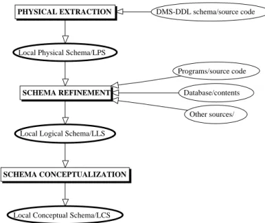
Recovering the logical and conceptual schemas of an existing local database is the main goal of Database Reverse Engineering (DBRE). The InterDB approach relies on the general DBRE methodology that has been developed in the DB-MAIN project and the architecture of which is outlined in Fig. 7. It shows clearly the three main processes that implement the three steps mentioned above. They will be described in Sections 4.1.1 to 4.1.3.
This methodology can be specialized according to the various data models which most legacy systems are based on, such as standard files, CODASYL, IMS and relational databases. The reader interested in more detail on the DB-MAIN reverse engineering approach is suggested to consult references.10,11,12 Alternative appproches can be found in references.13,14
4.1.1. Physical extraction
This phase consists in recovering the local physical schema (LPS) made up of all the structures and constraints explicitly declared. Databases systems generally provide a description of this schema (catalogue, data dictionary contents, DLL texts, file sections, etc.). The process consists in analyzing the data structure declaration statements (in the specific DLL) or the contents of these sources. It produces the LPS. The process is more complex for file systems, since the only formal descriptions available are declaration fragments spread throughout the application programs. This process is often easy to automate since it can be carried out by a simple parser which analyses the DMS-DDL texts, extracts the data structures and expresses them as the LPS. For instance, several popular CASE tools include some sorts of extractors, generally limited to RDB, but sometimes extended to COBOL files and IMS databases.
SCHEMA CONCEPTUALIZATION SCHEMA REFINEMENT PHYSICAL EXTRACTION
Local Conceptual Schema/LCS Local Logical Schema/LLS
DMS-DDL schema/source code
Local Physical Schema/LPS
Programs/source code Database/contents
Other sources/
Fig. 7. A generic DBRE methodology. The main processes extract the physical schema (LPS), refine it to produce the logical schema (LLS) and interpret the latter as a conceptual schema (LCS).
4.1.2. Schema refinement
The LPS is a rich starting point that must be refined through the analysis of the other components of the applications (views, subschemas, screen and report layouts, programs, fragments of documentation, program execution, data, etc.). This schema is then refined by specific analysis techniques11 that search non-declarative sources of information for evidences of implicit constructs and constraints. This schema is finally cleaned by removing its non-logical structures such as access keys and files. In this phase, three techniques are of particular importance.
1. Program analysis. This process consists in analyzing parts of the application
programs (the procedural sections, for instance) in order to detect evidences of additional data structures and integrity constraints.
2. Data analysis. This refinement process examines the contents of the files and
databases in order (1) to detect data structures and properties (e.g., to find unique fields or functional dependencies in a file), and (2) to test hypotheses (e.g., Could this
field be a foreign key to this file?).
3. Schema analysis. This process consists in eliciting implicit constructs (e.g., foreign keys) from structural evidence, in detecting and discarding non-logical structures (e.g., files and access keys), in translating names to make them more meaningful, and in restructuring some parts of the schema.
4.1.3. Schema conceptualization
This process addresses the semantic interpretation of a logical schema, from which one tries to extract a conceptual schema. The objective is to identify and to extract all the relevant semantic concepts underlying the logical schema. It mainly consists in detecting and transforming, or discarding, non-conceptual structures. Any logical schema can be obtained by a chain of transformations applied to the source conceptual schema. The conceptualization process can then be modeled as the undoing of the
conceptual-to-logical translation, that is, applying the inverse transformations. Three different problems
have to be solved through specific transformational techniques and reasoning.
1. Untranslation. Considering a target DBMS model, each component of a conceptual schema can be translated into DBMS-compliant constructs through a limited set of transformation rules. The identification of the traces of the application of these rules and the replacement of DMS constructs with the conceptual constructs they are intended to translate, form the basis of the untranslation process.
2. De-optimization. Most developers introduced, consciously or not, optimization constructs and transformations in their logical schemas. These practices can be classified into three families of techniques, namely structural redundancies (adding derivable constructs), unnormalization (merging data units linked through a one-to-many relationship) and restructuring (such as splitting and merging tables). The
de-optimization process consists in identifying such patterns, and discarding them, either
by removing or by transforming them.
3. Normalization. This process is similar to the conceptual normalization process. It consist in restructuring the raw conceptual schema obtained in Steps 1 and 2 in order to give it such qualities as readability, conciseness, minimality, normality and conformity to a corporate methodology standard.
The result of this process is the local conceptual schema (LCS).
4.2. Local schema integration
Integration is the process of identifying the objects in different local conceptual schemas which are related to one another, identifying and solving the conflicts of these schemas, and finally, merging local conceptual schemas into a global one.2
4.2.1. Conflict identification
Identifying the syntactic and semantic conflicts of independent schemas has long been studied in the database realm.15,16 Conflicts occur in three possible ways: syntactic,
semantic and instance. Besides the usual conflicts related to synonyms and homonyms, a
syntactic conflict occurs when the same concept is presented by different object types in
local schemas. For instance, an OrderDetail can be represented by an entity, by an attribute value and by a relationship. A semantic conflict appears when a contradiction appears between two representations A and B of the same application domain concept or between two integrity constraints. Solving such conflicts uses reconciliation techniques, generally based on the identification of set-theoretic relationships between these representations: A = B, A in B, A and B in AB, etc. Instance conflicts are specific to existing data. Though their schemas agree, the instances of the databases may conflict.
As an example, common knowledge suggests that USER be a subtype of EMPLOYEE. However, data analysis shows that inst(EMPLOYEE) ⊆ inst(USER), where inst(A) denotes the set of instances of data type A. This problem has been discussed in reference.[17Vermeer, 1996] This process is highly knowledge-based and cannot be
performed automatically. 4.2.2. Conflict resolution
Solving the conflicts occurring in heterogeneous databases has been studied in numerous references, e.g., references.15,16,17,18 It is important to note that most conflicts can be
solved through four main techniques that are used to rework the local schemas before their integration: renaming, generalizing, transforming and discarding.
1. Renaming. Constructs that denote the same application domain concepts are given the same name.
2. Generalizing. If two constructs denote the same application domain concept, and if one of them is more constrained, the constraint is relaxed. For example, a [0-10] cardinality conflicts with a [1-N] cardinality. Both will be replaced with cardinality [0-N], which is the strongest constraint compatible with both source cardinalities. 3. Transforming. An application domain concept can be represented by constructs of
different nature in source schemas. A supplier can be represented by an entity type in schema 1 and by an attribute in schema 2. The latter construct will be transformed into an entity type to give both representations the same nature.
4. Discarding. A construct that conflicts with others can be merely ignored. This is the case when the former appears to be a wrong translation of the application domain concept.
4.2.3. LCS merging
Since the syntactic, semantic and instance conflicts have been resolved by restructuring the local schemas, merging the latter is fairly straightforward, and can be automated to a large extent. Note that conflict resolution need not be completed as a preliminary process. Indeed, conflicts can be completely or partially solved when merging schemas. According to a strategy proposed in reference16, the source schemas are left unchanged,
and merging each pair of (sets of) constructs can imply on-the-fly restructuring in order to solve conflicts.
4.2.4. Practical InterDB methodology
The InterDB approach does not impose strict guidelines to integrate schemas. Experience has shown that this process must be coped with through very flexible techniques, and that different problems in the same project may require different techniques. In addition, steps generally addressed in theoretical approaches to schema integration are of a lesser importance in the InterDB framework since they have been performed in the reverse engineering process. This is the case for conflict identification and conflict resolution.
Indeed, the conceptualization phase (Section 4.1.3) has given analysts a strong knowledge of the semantics of each construct of the local conceptual schemas. In
addition, the normalization step (Section 4.1.3/3) should have produced fairly neutral schemas, in which few complex representation conflicts should remain. Therefore, identifying similar constructs and merging them is much easier than when one processes still unidentified logical schemas as proposed in most federated schema building methodologies (see references15,2 for instance).
The InterDB approach recommends flexible and adaptative procedures, that are supported by the DB-MAIN CASE tool, as will be shown in Section 5. Two main complementary strategies are proposed. They will be described as scenarios for integrating two schemas, though they can be generalized to N-ary strategies. In actual situations, both strategies can be used alternately to solve different parts of the integration work.
Synthetic strategy
This procedure is proposed for situations in which semantically similar parts of the schemas have almost identical representations. It is based on the following denotation assumptions:
• two objects of the same nature (entity type, relationship type or attribute) with the same name denote exactly the same application domain concept,
• any pair of objects that does not satisfy this condition denote independent application domain concepts.
This traditional strategy includes two sequential steps.
1. Pre-integration. This step is intended to make both schemas satify the denotation assumptions. Similar objects are identified and, if needed, their name and nature are modified accordingly. New objects can be introduced. For instance, if entity type E2 in schema 2 is recognized as a subtype of E1 in schema 1, then an empty entity type with name E1 is created in schema 2, and made a supertype of E2.
2. Global merging. The schemas are merged according to the denotation assumptions. It is based on the following rules:
• if two entity types have the same name, they are merged, i.e., only one is kept, and their attributes are merged; non matching attributes of both entity types are kept; • if two attributes of merged objects have the same name, they are merged, i.e., only
one is kept, and their attributes, if any, are merged; non matching attributes of both parent objects are kept;
• if two relationship types have the same name, they are merged, i.e., only one is kept and their roles and attributes are merged; non matching roles and attributes of both relationship types are kept;
• if two roles of merged relationship types have the same name, they are merged, i.e., only one is kept, and their attributes, if any, are merged.
This leads to a straighforward algorithm that can be easily automated.
Analytical strategy
The second strategy will be used in more complex situations. It consists in integrating pairs of constructs individually.
1. Identifying similar constructs and their semantic relation. The process is based on the knowledge gained by the analyst during the reverse engineering process, and on similarities between related parts on the source schemas (such as name and structural closeness). The semantic relation is identified. We suggest to choose one of the following five situations:
• identity: the constructs denote the same concept;
• complementarity: the constructs represent two facets of the same concept;
• subtyping: one construct denotes a subclass of the concept denoted by the other one;
• common supertype: both constructs denote subclasses of an implicit concept; • independence: the constructs denote independent concepts.
2. Solving representation conflicts. If necessary, names are changed and transformations are applied to make merging in step 3 easier.
3. Merging. We consider the typical binary strategy in which the master schema is enriched from the contents of a slave schema, which remains unchanged. According to the five situations identified in step 1, applied to constructs M in the master schema, and S in the slave schema, six actions will be proposed.
• identical(M,S): the components of S are transfered to M;
• complementarity(M,S): a copy of S is created in the master schema and is linked to M;
• subtype_of(M,S): a copy of S is created in the master schema and is made a subtype of M;
• subtype_of(S,M): a copy of S is created in the master schema and is made a supertype of M;
• common_supertype(M,S): a copy of S is created in the master schema and a new construct is created and made the common supertype of M and S;
• independent(M,S): if the relation is true for all M's, a copy of S is created in the master schema.
To make things more complex, the process must be considered recursively. Indeed, each construct generally has components: an entity type has a name, attributes, roles, constraints and textual annotations; an attribute has a name, a type, a length, sub-attributes and textual annotations; a relationship type has a name, roles, sub-attributes and textual annotations; a role has a name, cardinality, one or several participating entity types and textual annotations.
In each merging technique (but the last one) the components of M and S must be compared pairwise, to identify their semantic relation and to decide on their integration strategy. For instance, considering attribute AS of S, either AS is identical to attribute AM of M, in which case they will be merged, or AS must be added to M. In the former case, C components (name, type, annotation, etc.) of AS and AM are compared pairwise. Either they match, in which case AM.C is kept, or they conflict, in which case a human decision must be made: either AM.C or AS.C is
kept, or a combination of both is adopted as AM.C (e.g., the concatenation of the annotations).
4.3. Building the inter-schema mappings
A careful analysis of the processes that have been described in 4.1 and 4.2 shows that deriving a schema from another one is performed through techniques such as renaming, translating, conceptualizing, solving conflicts, which basically are schema
transformations. As suggested in reference19, most database engineering processes can
be formalized as a chain of schema transformations. This is the case for reverse engineering and schema integration.20
Roughly speaking, a schema transformation consists in deriving a target schema S’ from a source schema S by replacing construct C (possibly empty) in S with a new construct C' (possibly empty). Adding an attribute to an entity type, extracting an attribute as an entity type, replacing a relationship type with an equivalent entity type or with a foreign key are some examples of schema transformations.
More formally, a transformation T is defined as a couple of mappings <T,t> such that, for any construct C to which T is applicable:
C' = T(C)
inst(C') = t(inst(C))
Structural mapping T explains how to modify the schema while instance mapping t states how to compute the instance set of C' from the instances of C.
Any transformation T ≡ <T,t> can be given an inverse transformation Ti ≡ <Ti,ti>, such that Ti(T(C)) = C. If, in addition, we also have, for any instance c of C: ti(t(c)) = c, then Τ is declared semantics-preserving. A compound transformation T12 = T2oT1 is obtained by applying T2 to the database that results from the application of T1. These concepts and properties have been analyzed in detail in reference.19
An important conclusion of the transformation-based analysis of database engineering processes is that most of them can be modeled through semantics-preserving transformations. For instance, conceptualizing logical schema LLS into conceptual schema LCS (Section 4.1.3) can be modeled as a compound semantics-preserving transformation L-to-C = <L-to-C,l-to-c> in such a way that:
LCS = L-to-C(LLS)
This transformation has an inverse: C-to-L = <C-to-L,c-to-l> such that: LLS = C-to-L(LCS)
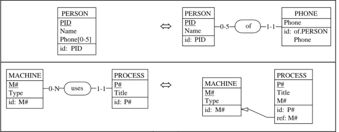
Fig. 8 illustrates two semantics-preserving transformations that are commonly used in reverse engineering and in schema integration.
Finally, the conceptual/logical mappings between the logical data and the conceptual
data can be derived from the instance mappings:
inst(LCS) = l-to-c(inst(LLS))
PERSON PID Name Phone[0-5] id: PID
⇔
PERSON PID PHONE Phone id: of.PERSON Phone of 1-1 0-5 Name id: PID⇔
1-1 uses PROCESS P# Title id: P# MACHINE M# PROCESS P# MACHINE M# 0-N Title M# id: P# ref: M# Type id: M# Type id: M#Fig. 8. Two popular semantics-preserving schema transformations. The first example explains how a multivalued attribute can be expressed as an external entity type. The second one shows the transformation of a relationship type into a foreign key. Only the structural mappings of both transformations are shown.
Now, we are able to describe the physical/conceptual mappings for local databases. In addition to the conceptual/logical mappings mentioned above, we consider the logical/physical mappings P-to-L = <P-to-L,p-to-l> and its inverse L-to-P =
<L-to-P,l-to-p>. A local server will rely on the compound mapping [C-to-LoL-to-P] to translate
queries, and on the compound mapping [p-to-lol-to-c] to form the result instances.
Of course, these mappings appear as pure functions that cannot be immediately translated into executable procedures in 3GL. However, it is fairly easy to produce procedural data conversion programs as shown in reference.20
5. CASE support
Deriving a common, abstract and conflict-free image of independent databases, defining the mappings between the specification layers, building the local servers and the global repository are complex and time consuming tasks that are out of the competence of most developers.
These processes are supported by an extension of the DB-MAIN CASE toola. This graphical, repository-based, software engineering environment is dedicated to database
applications engineering. Besides standard functions such as specification entry,
examination and management (Fig. 9), it includes advanced processors such as transformation toolboxes, reverse engineering processors and schema analysis tools.
It also provides powerful assistants to help developers and analysts carry out complex and tedious tasks in a reliable way. The assistants offer scripting facilities through which method fragments can be developed and reused.
aAn Education version of the DB-MAIN CASE environment as well as various materials of the DB-MAIN laboratory can be obtained at http://www.info.fundp.ac.be/~dbm
Fig. 9. DB-MAIN can display a schema in six different formats. This screen copy shows four of them: text extended (left), text sorted (bottom), graphical compact (top) and graphical standard (right).
One of the main features of DB-MAIN is the Meta-CASE layer, which allows method engineers to customize the tool and to add new concepts, functions, models and even new methods. In particular, DB-MAIN offers a complete development language, Voyager 2, through which new functions and processors can be developed and seamlessly integrated into the tool. The InterDB CASE tool has been built on top of the DB-MAIN tool by adding concepts and processors that support the specific InterDB architecture and methodology described in Sections 3 and 4. We will describe how the CASE tool can aid in carrying out the main engineering processes and in producing the main architecture components.
5.1 Reverse engineering support
DB-MAIN offers functions and processors that are specific to DBRE.12 The physical
extraction process is carried out by a series of processors that automatically extract the
data structures declared into a source text. These processors identify and parse the declaration part of the source texts, or analyze catalog tables, and create corresponding abstractions in the repository. Extractors have been developed for SQL, COBOL, CODASYL, IMS and RPG data structures. Additional extractors can be developed easily thanks to the Voyager 2 environment which includes lexical analysis and list management functions.
The schema refinement process is supported by a collection of processors such as: • a pattern matching engine that can search a source text for definite patterns such as
• a variable dependency analyzer that detects and displays the dependencies between the objects (variables, constants, records) of a program (program analysis);
• a program slicing tool that computes the set of program statements that contribute to the state of a selected variable at a selected point (line) of a source program (program analysis).
• a facility to quickly develop Voyager 2 generators of program/queries to examine data (data analysis);
• a foreign key assistant that helps find the possible foreign keys of a schema through structural analysis (schema analysis);
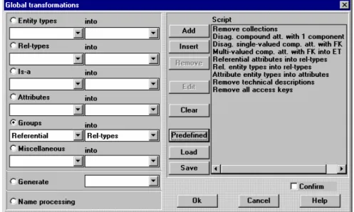
The conceptualization process can be performed in a reliable way thanks to a rich semantics-preserving transformation toolset. Transformation scripts that implement specific heuristics can be quickly developed (Fig. 10). A programmable schema analysis processor can be used to detect structural patterns and problematic constructs to be further analyzed.
Fig. 10. The Basic Global Transformation assistant allows the analyst to perform a transformation on all the objects that satisfy a condition (left part). This screen copy shows that the analyst has developed a small script (right part) to conceptualize a COBOL schema. More complex scripts can be developed with the Advanced Global Transformation assistant.
5.2 Schema integration support
Schema integration occurs mainly when merging the local conceptual schemas into the global schema. It also appears in reverse engineering to merge multiple descriptions into a unique logical schema. In addition, several strategies can be applied, depending on the complexity and the heterogeneity of the source databases and on the skill of the analyst. As a consequence, DB-MAIN offers a toolbox for schema integration instead of a
unique, automated, schema integrator. Together with the transformation toolbox, the integration toolbox allows manual, semi-automatic and fully automatic integration. The
synthetic strategy is supported by a schema integration processor that is based on the
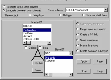
denotation assumptions. The analytical strategy uses different processors, the most important of which is the object integration assistant. Fig. 11 shows the integration of entity types ORDER and ORD of Fig. 3. When asserting that ORDER.OrdNumber and ORD.Ord-Code are the same (Fig. 11, button Same), the assistant compares their properties and presents them whenever a conflict is detected. Solving this conflict is up to the analyst (Fig. 12).
Fig. 11. The integration assistant. Entity types ORDER in schema SQL/Conceptual and ORD in schema COBOL/Conceptual are examined for integration. Among the six integration strategies, the analyst chose the fourth one, according to which ORDER is a supertype for ORD. The attributes and roles are compared and either migrated (button <<Move) or merged (button Same). Here, the analyst is going to tell that attributes OrdNumber and OrdCode have the same semantics, and that only the first one must be kept.
5.3 Mapping building
This function is not a specific component of InterDB support, but rather is a by-product of all the engineering activities. Indeed, DB-MAIN automatically generates and maintains a history log (say h) of all the activities that are carried out when the developer derives a schema B from schema A.
This history is completely formalized in such a way that it can be replayed, analyzed and transformed. For example, any history h can be inverted into history h'. Histories
must be normalized to remove useless sequences and dead-end exploratory branches. History h of the reverse engineering process that produces the conceptual schema LCS of a local database from its physical schema LPS can be considered as a structural mapping. In other words, h ≡ [P-to-L o L-to-C], according to the notation of Section 4.3. History processing, including inversion, has been described in reference.20
Fig. 12. The integration assistant: resolving the conflicting properties of attributes OrdNumber and OrdCode that have been declared to be the same. Three conflicting properties have been identified: name, type and semantic description.
5.4 Local server generation
The inverted history yields a fictitious history of how the database could have been produced. In fact h' ≡ [C-to-L o L-to-P]. Let us now consider t, the instance mapping of h, that is, t = [p-to-l o l-to-c]. Formally, {h',t} is the functional specification of the local servers. Indeed, structural mapping h' can be used to translate conceptual queries into physical queries, while instance mapping t explains how to convert physical data into conceptual data. In summary, history h includes all the necessary information to generate the local server components.
Generators have been developed in Voyager 2 to produce the logical and physical modules. At the current time, generators for COBOL files and RDB data structures are available. Fig. 13 shows the organization of the generators. For each abstraction level, two documents are produced, namely a package that allows programs to interface with the data and the documentation for programmers. The inter-schema mappings are used to generate the local servers, each comprising a logical module and a conceptual module. Note that nothing is generated for local/global correspondence since the latter is in the global repository.
Logical API Generator
Logical Module Generator Conceptual Module Generator
Conceptual API Generator
Conc. Program. Interface/Data structures Conc. Program. Interface/documentation
Conceptual module/code
Log. Program. Interface/Data structures Local Logical schema/LLS
Log. Program. Interface/documentation
Logical module/code
Local Physical schema/LPS Local Conceptual schema/LCS
Fig. 13. Generation of the FDB architecture components. Three kinds of output are available: documentation, modules (code) and programming interfaces (Data structures).
5.5 The global repository
The global server has not been developed yet. It will rely on a global repository which will be a simplified and autonomous variant of the repository of the DB-MAIN CASE tool.
This repository is an OO database managed by a custom-made, high performance, DBMS which has been developed as a C++ platform-independent module.
6. Conclusions
Database interoperability has been studied for years, leading to architectures that can be considered standard. The InterDB contribution is at the methodological level. It proposes a comprehensive process that integrates known techniques such as database reverse engineering, schema integration and query decomposition, with new ones, such as mapping building and component generation. This approach is supported by a general purpose CASE tool in which standard functions have been augmented with specific functions, assistants and processors dedicated to reverse engineering, schema integration, history processing and architecture component generation.
It appears that processes such as reverse engineering and schema integration require strong skills from the analyst. Therefore, CASE technology can only help him carry out these processes, but cannot automate them, except in very simple and academic situations.
One of the most challenging issues was building the inter-schema mappings. Thanks to a formal transformational approach to schema engineering, it was possible to build the mappings that drive the query decomposition and the data recomposition required by the hierarchy of schemas.
Though important issues have not been tackled so far, such as global query processing and transaction management, the architecture as well as the methods and engineering tools we have developed cope in an elegant way with all the heterogeneity dimensions that appear when one integrates existing, independently developed databases.
A short analysis of the market shows that no current CASE tools can help either in reverse engineering complex databases, or in building the components of the architecture. Hence the importance of the DB-MAIN CASE tool and particularly of its
Voyager 2 meta-language that allowed us to develop repository-based analyzers and local
server generators. An interesting feature of the architecture is that the global repository of the global server is the repository of the CASE tool as well.
Acknowledgements
The comments by the anonymous reviewers, as well as those of Jim Geller, were most useful in improving the readability and the consistency of this paper, and to make it as informative as possible. Thanks to them.
References
1. A. Bouguettaya, B. Benattallah and A. Elmagarmid, Interconnecting Heterogeneous
Information Systems, (Kluwer Academic Publishers, Norwell, USA, 1998).
2. A.P. Sheth and J. A. Larson, Federated Database Systems for Managing Distributed, Heterogeneous, and Autonomous Databases, ACM Computing Surveys, 22(3), (1990) 183-236. 3. A. Dogac et al., METU Interoperable Database System, SIGMOD RECORD, Vol. 24(3),
(1995) 56-61, .
4. E. Kilic et al, Experiences in Using CORBA for a Multidatabase Implementation, in Proc. of
6th Intl. Workshop on Database and Expert System Applications, London, (1995), 223-230.
5. A. Dogac et al., A Multidatabase System Implementation on CORBA, in Proc of 6th Intl.
Workshop on Research Issues in Data Engineering (RIDE-NDS’96), New Orleans, USA,
(1996) 2-11.
6. M.T. Özsu and P. Valduriez, Principles of Distributed Database Systems, (Prentice Hall, Englewood Cliffs, USA, 1991).
7. G. Wiederhold, Mediators in the Architecture of Future Information Systems, IEEE
Computers, (1992) 38-49.
8. H.S. Sneed, Encapsulating Legacy Software for Use in Client/Server Systems. Proc. of the 3rd
IEEE Working Conf. on Reverse Engineering, Monterey, Nov. 1996, (IEEE Computer Society
Press, 1996) 104-120.
9. M. Fowler and K. Scott, UML Distilled - Applying the Standard Object Modeling Language, (Addison-Wesley, Reading, 1997)
10. J-L. Hainaut, M. Chandelon, C. Tonneau and M. Joris, Contribution to a Theory of Database Reverse Engineering, in Proc. of the IEEE Working Conf. on Reverse Engineering, Baltimore, May 1993, (IEEE Computer Society Press, 1993) 161-170.
11. J-L. Hainaut, J. Henrard, D. Roland, V. Englebert and J-M. Hick, Structure Elicitation in Database Reverse Engineering, in Proc. Of the 3rd IEEE Working Conf. On Reverse Engineering, Monterey, Nov. 1996, (IEEE Computer Society Press, 1996) 131-140.
12. J-L. Hainaut, D. Roland, J-M. Hick, J. Henrard and V. Englebert, Database Reverse Engineering: from Requirements to CARE tools, Journal of Automated Software Engineering,
13. H. Gall and R. Klösh, Finding Objects in Procedural Programs: An Alternative Approach. Proc. of the 2nd IEEE Working Conf. on Reverse Engineering, Toronto, July 1995, (IEEE Computer Society Press, 1995) 208-216.
14. M. Blaha and W. Premerlani, Object-Oriented Modeling and Design for Database
Applications, (Prentice Hall, Upper Saddle River, USA, 1998).
15. C. Batini, M. Lenzerini and S.B. Navathe, A Comparative Analysis of Methologies for Database Schema Integration, ACM Computing Surveys, 18(4), (1986) 323-364.
16. S. Spaccapietra and C. Parent, “Conflicts and correspondence assertions in interoperable databases”, ACM SIGMOD Record, 20(4), (1991) 49-54.
17. M.W.W. Vermeer and P.M.G Apers, On the Applicability of Schema Integration Techniques to Database Interoperation, in Proc. of 15th Int. Conf. On Conceptual Modelling, ER’96, Cottbus, Oct. 1996, (Springer-Verlag, 1996) 179-194.
18. C. Parent and S. Spaccapietra, Issues and Approaches of Database Integration,
Communications of the ACM, 41(5), (1998) 166-178.
19. J-L. Hainaut, Specification preservation in schema transformations - Application to semantics and statistics, Data & Knowledge Engineering, 19 (Elsevier Science Publish, 1996) 99-134,. 20. J-L. Hainaut, J. Henrard, J-M. Hick, D. Roland and V. Englebert, Database Design Recovery,
in Proc. of the 8th Conf. on Advanced Information Systems Engineering (CAISE'96), (Springer-Verlag, 1996) 272-300.