Publisher’s version / Version de l'éditeur:
Vous avez des questions? Nous pouvons vous aider. Pour communiquer directement avec un auteur, consultez la
première page de la revue dans laquelle son article a été publié afin de trouver ses coordonnées. Si vous n’arrivez pas à les repérer, communiquez avec nous à [email protected].
Questions? Contact the NRC Publications Archive team at
[email protected]. If you wish to email the authors directly, please see the first page of the publication for their contact information.
https://publications-cnrc.canada.ca/fra/droits
L’accès à ce site Web et l’utilisation de son contenu sont assujettis aux conditions présentées dans le site LISEZ CES CONDITIONS ATTENTIVEMENT AVANT D’UTILISER CE SITE WEB.
Student Report (National Research Council of Canada. Institute for Ocean Technology); no. SR-2005-26, 2005
READ THESE TERMS AND CONDITIONS CAREFULLY BEFORE USING THIS WEBSITE.
https://nrc-publications.canada.ca/eng/copyright
NRC Publications Archive Record / Notice des Archives des publications du CNRC :
https://nrc-publications.canada.ca/eng/view/object/?id=21a9a810-b83e-44fe-b74b-8a3768d4bd0a https://publications-cnrc.canada.ca/fra/voir/objet/?id=21a9a810-b83e-44fe-b74b-8a3768d4bd0a
NRC Publications Archive
Archives des publications du CNRC
For the publisher’s version, please access the DOI link below./ Pour consulter la version de l’éditeur, utilisez le lien DOI ci-dessous.
https://doi.org/10.4224/8895146
Access and use of this website and the material on it are subject to the Terms and Conditions set forth at
Institute for Ocean Technology Network Security: implementing a dual firewall system
DOCUMENTATION PAGE REPORT NUMBER
SR-2005-26
NRC REPORT NUMBER DATE
15 Dec 2005
REPORT SECURITY CLASSIFICATION
Unclassified
DISTRIBUTION
Unlimited
TITLE
Institute for Ocean Technology Network Security – Implementing a Dual Firewall System
AUTHOR(S)
Mike Murphy
CORPORATE AUTHOR(S)/PERFORMING AGENCY(S)
PUBLICATION
SPONSORING AGENCY(S)
National Research Council – Institute for Ocean Technology
IOT PROJECT NUMBER
421020
NRC FILE NUMBER KEY WORDS
Firewall, Network, Security
PAGES 23 FIGS. 10 TABLES SUMMARY
The computer network at IOT is an integral part of everyday work. All files, programs, simulations and data are very important and security is of the utmost concern.
The firewall is one of the most important security devices in our network, and must be maintained at a level such that it can provide a reliable and efficient security barrier for our network.
To meet this end, it has become necessary to update the current firewall system (a single machine) to a dual-machine system so that if one of the firewalls crashes the network will still be operational and secure.
A number of proposals with which to accomplish this are presented in this report, and a recommendation made on the method of implementation.
ADDRESS National Research Council Institute for Ocean Technology Arctic Avenue, P. O. Box 12093 St. John's, NL A1B 3T5
National Research Council Conseil national de recherches Canada Canada Institute for Ocean Institut des technologies Technology océaniques
INSTITUTE FOR OCEAN TECHNOLOGY NETWORK SECURITY
– IMPLEMENTING A DUAL FIREWALL SYSTEM
SR-2005-26
Mike Murphy
T
ABLE
O
F
C
ONTENTS
1 – INTRODUCTION... 1
1.1 – R
EPORTP
LAN... 11.2 – F
IREWALLS... 11.3 – F
IREWALLR
ULES... 2 1.3.1 - IP ADDRESS ... 2 1.3.2 - DOMAIN NAME... 31.3.3 - PROTOCOLS AND PORTS... 3
1.4 – F
IREWALL ASNAT S
ERVER... 31.4.1 - STATIC NAT ... 4
1.4.2 - DYNAMIC NAT ... 4
1.4.3 - PORT ADDRESS TRANSLATION... 4
1.5 – A
UTOMATICS
WITCHOVER... 52 – IOT FIREWALL SYSTEMS... 6
2.1 – I
NTRODUCTION... 62.2 – D
ARKB
LUE... 6 2.2.1 – RAID SYSTEM ... 7 2.2.2 – OPERATING SYSTEM/SOFTWARE ... 82.3 – FW2 & FW3
... 9 2.3.1 – RAID SYSTEM ... 9 2.3.2 – OPERATING SYSTEM/SOFTWARE ... 102.4 – P
LAN FORF
AILOVER... 103 – IOT NETWORK... 11
3.1 - O
VERVIEW... 113.2 – N
ETWORKA
RCHITECTURE... 113.3 – P
LAN FORF
IREWALLU
PGRADE... 124 – PROPOSED IMPLEMENTATION... 14
4.1 – I
NTRODUCTION... 144.2 – P
ROPOSAL1: F
OURS
WITCHES... 144.3 – P
ROPOSAL2: D
IRECTF
IBRE TOA
CCELAR... 154.4 – P
ROPOSAL3: G
IGABITC
OPPER FROMC
ISCO7200
... 154.5 – P
ROPOSAL4: VPN D
IRECT TOA
CCELAR... 164.6 – C
HOICE OFP
ROPOSAL... 17T
ABLE OF
F
IGURES
F
IGURE1. P
ROPERLY PLACED AND CONFIGURED FIREWALL...1
F
IGURE2. S
AMPLEP
ORTA
DDRESST
RANSLATION LOOKUP TABLE...5
F
IGURE3. D
ARKB
LUE:
A)
FRONT;
B)
NO COVER,
SEEINGRAID
DISKS;
C)
INSIDE,
SEEING INTERFACES ANDRAID
C
ONTROLLER...6
F
IGURE4. FW2:
A)
FRONT;
B)
COVER OPENED TO SHOWRAID
DISKS;
C)
COPPER NETWORK INTERFACES;
D)
FIBRE OPTIC NETWORK INTERFACES;
E)
TOP REMOVED TO SHOWRAM, RAID
CONTROLLER ANDCPU ...9
F
IGURE5. IOT N
ETWORKD
IAGRAM...13
F
IGURE6. F
OUR-
SWITCH PROPOSAL...14
F
IGURE7. D
IRECT-
TO-A
CCELAR PROPOSAL...15
F
IGURE8. C
OPPER FROMC
ISCO7200
PROPOSAL...16
F
IGURE9. VPN
TOA
CCELARP
ROPOSAL...17
F
IGURE10. P
ROPOSEDIOT N
ETWORKD
IAGRAM AFTER IMPLEMENTATION OF DOUBLE FIREWALL...18
A
CKNOWLEDGEMENTS
During my work term from August – December 2005 at the National Research Council’s Institute for Ocean Technology I learned an incredible amount about computer network design and architecture, as well as gaining valuable experience in many other nuances of
the computing world. This would not have been possible without the help of the incredible people in the Computer Systems group, so I would like to thank Group Leader
Paul Thorburn, Wayne Elms, Ray Wadman, Gilbert Wong, and special thanks to Doug Walsh, whose project this actually was and for putting up with my uninformed foolish
ideas while teaching me how it’s supposed to be done.
I’d also like to thank my fellow IOT co-op students Tyler, Jeswin, Gerry, Chris and Earl, as well as the Compass Club, Pete Hackett, Chris Meadus and Gerry Trepanier for
S
UMMARY
The computer network at IOT is an integral part of everyday work. All files, programs, simulations and data are very important and security is of the utmost concern.
The firewall is one of the most important security devices in our network, and must be maintained at a level such that it can provide a reliable and efficient security barrier for our network.
To meet this end, it has become necessary to update the current firewall system (a single machine) to a dual-machine system so that if one of the firewalls crashes the network will still be operational and secure.
A number of proposals with which to accomplish this are presented in this report, and a recommendation made on the method of implementation.
1 I
NTRODUCTION
1.1 Report Plan
This is a technical report completed during my work term at the National Research Council’s Institute for Ocean Technology in St. John’s, beginning on August 22 and concluding on December 16, 2005. This paper will discuss the network structure of the Local Area Network, along with the process of designing and implementing an
automatic-switchover redundant firewall as part of that network. However, in the interests of security, no firewall rules or specific IP addresses will be included in this report.
1.2 Firewalls
A firewall in computer terms is a lot like a physical firewall, which protects an area against the spread of a fire. It can be either hardware or software, and has the task of filtering all incoming and outgoing traffic seen to it. For this reason a firewall must be placed in a position to see all traffic it needs to filter. Figure 1 shows a firewall in action, providing protection for a computer.
Firewalls can use three different methods for network traffic control: packet filtering, proxy services, and stateful inspection1. In packet filtering, all incoming “packets” or bundles of network information are compared against a set of filters, and if the packet matches a bad filter it is “dropped” or discarded. Using the firewall as a proxy server means that all information to or from the computers inside the firewall must be requested from the firewall, which then fetches or delivers the traffic. This can be accomplished by using the firewall as a Network Address Translation (NAT) server. Stateful inspection means that the firewall does not scan the entire packet, but matches key parts of a packet to a database defining allowed and unallowed traffic. The firewalls at IOT use a
conglomeration of all three of these types of filtering.
1.3 Firewall Rules
In order for a firewall to protect a network against dangerous traffic, it needs an idea about what traffic is considered dangerous. This is done through a set of “firewall rules” which tell the firewall what is or isn’t allowed. Firewall rules can be based on a number of key points:
• IP Address • Domain Names
• Protocols (TCP, UDP, FTP) • Port Numbers
• Specific words or phrases
A firewall rule generally follows the following grammar:
<action> <protocol> from <IP address, domain name> <port> to < IP address, domain name> <port> in/out via <interface> where action is something like allow or deny, interface is the name of the physical network device on the firewall which the traffic passes through, and the italicized portions are optional.
1.3.1 IP address
Every computer connected to a network or the Internet is assigned an IP address by the server. An IP address consists of four sets of numbers called octets, separated by periods. Each octet is a number from 0 – 255 (28 numbers, hence ‘octet’), and the combination of these numbers uniquely identifies each computer on the network. Another important aspect to an IP address is the netmask. The netmask is a binary ‘mask’, which, when applied against an IP address by way of a logical “AND” operation, shows the subnet to which the IP address belongs. The netmask in effect is the number of binary digits starting from the leftmost octet that are not uniquely identified with a specific computer.
1
For instance, let’s say we have a network whose internal addresses all begin with 10.1. A computer in this subnet could have the unique IP address 10.1.220.147. In this case the netmask is 255.255.0.0. The netmask can also be included directly in the IP address through a slash and the number of binary digits at the end of the address. In the above example, the IP address with netmask would be 10.1.220.147/16. This can be useful in firewall rule construction because it allows a full group of addresses to be covered by a single rule.
For example, to allow all traffic from any computer in the 10.1 subnet to anywhere, the firewall rule would look like this:
allow all from 10.1.0.0/16 to any 1.3.2 Domain name
A domain name can be used similarly to IP address in the formulation of firewall rules. In fact, a domain name is pretty much another formation of an IP address that is easier for humans to remember. The Domain Name System maps text-based names onto IP
addresses, and is hosted on a Domain Name Server (DNS). In actuality, when you direct your web browser to a web site like www.examplesite.com, your computer makes contact with a DNS and asks for the IP address associated with the domain address. If the DNS contacted doesn’t have the address in its database it passes the request on until the IP address is found. In this way, domain traffic can be controlled by the same rules as IP traffic. The firewall machine on the IOT network also handles the DNS duties for the network.
1.3.3 Protocols and ports
A protocol can be thought of as a language that computers use to speak to one another. Some of the more popular protocols in use today include Transmission Control Protocol (TCP), Internet Protocol (IP), and File Transfer Protocol (FTP). Generally, protocols request connection over a specific port. Think of the port as an access point to a system. If the protocol is recognized and the port is open, communication between the server and client can commence in the language of the protocol. Firewall rules can be used to block or allow specific protocol communication on one or all ports. Rules can also be
formulated to divert traffic originally destined for a certain port to another port. This is very important because some port numbers are well known as attack points for viruses and Denial-of-Service attacks and the firewall can provide security for these “bad” ports.
1.4 Firewall as NAT Server
Network Address Translation, when required, must be used on a device that sits between the network needing the translation and the outside world. Therefore, by definition, a firewall is the perfect place to house a NAT server. The purpose of NAT is to expand the
network namespace. There are a few different kinds of NAT, such as static NAT, dynamic NAT, and overloading or PAT (Port address translation)2.
1.4.1 Static NAT
Static NAT does not expand a network’s namespace, but simply maps internal addresses to external addresses on a one-to-one basis. For instance, let’s say an internal network has a private address space of 10.xxx.xxx.xxx. The 10.xxx.xxx.xxx address space is reserved for private networks, so any computer accessing outside sources must not appear to have this address on the Internet. Therefore, when our example computer of internal IP address 10.1.2.3 wishes to access an outside source, it first contacts the NAT server. The NAT server assigns our computer a new external IP address of 213.18.24.168, and sends out the information request. When a response comes back to the NAT server, the destination address is 213.18.24.168. The NAT server recognizes this address as the one it assigned to 10.1.2.3 earlier and passes along the data to the correct computer. 10.1.2.3 will always have an outside address of 213.18.24.168. This is the method to use when a network machine must be reliably accessed from outside the network.
1.4.2 Dynamic NAT
Dynamic NAT builds on the formula provided in static NAT, but uses a bit different method of assigning outside IP addresses. The NAT server has a range of registered addresses that it can use, but does not use them on a one-to-one basis. For instance, let’s say our internal network contains around 400 computers, but we have only been allocated 255 unique IP addresses from the local Internet Service Provider (ISP). We don’t expect to need any more than that, as there will be no more than 255 computers at the most accessing outside information at a time. The NAT server then has a range of registered IP addresses it can assign; for our example we’ll say the NAT address space is
213.18.24.xxx. When our internal 10.xxx.xxx.xxx computer attempts to make an outside connection, the NAT server assigns one of the addresses in its registered range to the computer and conducts the communication as in the static NAT example. In this case, however, when the outside communication is finished, the assigned 213.18.24.xxx address is “reclaimed” by the NAT server and returned to the pool of available addresses to be assigned to the next computer requesting an outside communication.
1.4.3 Port address translation
PAT, also known as overloading or single-address NAT, uses only one IP address; the one assigned to the NAT server. Instead of assigning an IP address to a computer requesting an outside communication, the NAT server simply assigns a port number to the communication. For example, let’s say the NAT server IP address is 213.24.18.88.
2
When a 10.xxx.xxx.xxx computer from the internal network attempts to contact a computer outside the network, it passes the request on to the NAT server. The NAT server then applies its own IP address to the packet, and also assigns a port to represent the network computer that requested the communication. This relationship is stored in a table that also has a time stamp. If no communication happens on that port before the time stamp reaches a specified age, then the port is reclaimed for use with the next outgoing connection. However any communication that does arrive at that port is forwarded along to the original computer as saved in the NAT server’s lookup table. Figure 23 shows a sample lookup table for a NAT server handling 4 connections.
Source Computer Source Computer's IP Address Source Computer's Port NAT Server's IP Address NAT Server's Assigned Port Number A 192.168.32.10 400 215.37.32.203 1 B 192.168.32.13 50 215.37.32.203 2 C 192.168.32.15 3750 215.37.32.203 3 D 192.168.32.18 206 215.37.32.203 4
Figure 2. Sample Port Address Translation lookup table
At IOT, the firewall uses this method (PAT) for address translation. Therefore, there is no need to worry about running out of external addresses for the network computers as they are all assigned the IP address of the firewall interface.
1.5 Automatic Switchover
At the commencement of this work term, the IOT network had a single firewall hosted on a machine called DarkBlue. The plan was to implement a dual-firewall system on two machines with the added failsafe of automatic switchover. This means that a design had to be constructed such that one of the new firewall machines would act as the primary firewall, but should a problem develop with that machine, the second would take over the tasks of the first without loss of security or network connections. This introduces another level of complexity in the design, and may or may not be feasible given budgetary and security concerns. This will be discussed in depth later in this report.
3
2 IOT F
IREWALL
S
YSTEMS
2.1 Introduction
In this chapter, the actual hardware and software of the firewall machines will be discussed. First the old firewall machine, DarkBlue, will be studied, and it’s reason for being replaced explained. Then the new systems will be studied, with reference to hardware, operating system, and firewall software.
2.2 DarkBlue
The current firewall machine, FW1 or DarkBlue, is housed on a Dell PowerEdge 2400 machine with dual Intel Pentium III processors and 1 GB of RAM. It also contains a 3 SCSI disk RAID-5 array along with two fibre optic network interfaces and two standard copper network interfaces. Figure 3 shows the machine DarkBlue.
a) b)
c)
Figure 3. DarkBlue: a) front; b) no cover, seeing RAID disks;
c) inside, seeing interfaces and RAID Controller
2.2.1 RAID system
RAID stands for redundant array of inexpensive disks and is a way to combine small, inexpensive disks in such a way that performance will exceed that of a single larger disk4. This is accomplished through data redundancy and parity checking. There are 5 “levels” or implementations of RAID, along with a sixth level that is not truly RAID in the strictest sense.
RAID-0 (Striping): Data is stored over multiple disks. Since redundant data is not used, this is not truly RAID. Loss of one disk means irrecoverable loss of data, but since the data is “striped” across the disk performance is high. At least two disks required.
RAID-1 (Mirroring): Each piece of data is saved on two drives. This lowers performance when compared with RAID-0, but the loss of any one drive means no loss of data. At least two disks required, and the resulting array has total space of (n-1) x individual disk size, where n is the number of disks in the array.
RAID-2 (Hamming error correction): Only used when drives don’t have built-in error detection. All SCSI drives (like the ones we have) do have error detection so this method is not useful with our setup.
RAID-3 (Bytewise Striping with Parity): Stripes data on a byte level across disks, and uses one disk as a parity disk. Therefore each byte of data gets saved on two disks and parity (used to check for data integrity) is stored on another disk. If a disk fails there will always be another copy of the data. At least three disks are required, and the resulting array has total space of (n-1) x individual disk size, where n is the number of disks in the array.
RAID-4 (Blockwise Striping with Parity): The same as RAID-3, but the data is striped on a block level.
RAID-5 (Striping with Distributed Parity): Similar to RAID-4, but instead of using one disk as a parity disk, the parity is shared among the disks. For example let’s say we have a three disk RAID-5 system. The first block of data will be written on disks 1 & 2, with the parity on 3. The next block will be written on disks 2 & 3, with the parity on 1. At least 3 disks are required for RAID-5. If one of the disks fails, the remaining disks can keep the system operational without the loss of data, in a mode called Reduced RAID-5. The RAID system used on the firewalls at IOT is RAID-5.
The RAID system on DarkBlue is one of the main reasons that the machine must be replaced. At an earlier date one of the disks failed, and in order to reintroduce the third disk to the RAID, it was necessary to flatten the whole system and rebuild it from scratch. This is because the RAID controller in DarkBlue is of suspect quality. Because DarkBlue
4
does such an important job in the IOT network, providing security, NAT service, Domain Host Configuration Protocol (DHCP) service, and Domain Name Service (DNS), it is not acceptable to suffer losses of this type. The newer RAID systems on the FW2 and FW3 machines should alleviate these concerns.
2.2.2 Operating system/software
DarkBlue is currently running the FreeBSD operating system, version 4.9 with a custom compiled kernel to eliminate any unnecessary drivers and kernel modules while
streamlining the boot process so the machine runs as efficiently as possible.
The firewall software used, IPFW, is compiled directly into the kernel and provides a numbered list of rules with which to authenticate incoming and outgoing traffic. IPFW is an advanced software package and detailed knowledge into the different protocols used is necessary to use the software to its full potential. IPFW consists of seven main
components; the kernel firewall filter rule processor and its integrated packet accounting facility, the logging facility, the 'divert' rule (which triggers the NAT facility), the dummynet traffic shaper facilities, the 'fwd rule' forward facility, the bridge facility, and the ipstealth facility5.
The NAT server and DHCP servers are handled by their own packages, called natd and dhcpd respectively. Both packages have configuration files that define ranges of IP addresses to be used. These daemons are configured to run at system startup, and have been configured to meet the needs of the network users at IOT. The NAT server operates as described in chapter 1, while the DHCP server has the task of assigning dynamic IP addresses to DHCP-enabled computers (those without a static IP address, such as laptops), and keeping track of the addresses it assigns.
The DNS server on DarkBlue is handled by a package called BIND (Berkeley Internet Name Domain). BIND consists of a daemon called named which is run at system boot, as well as a control program called ndc. Again, BIND has a configuration file, which must be used to set up the zones that the DNS must serve. If a computer somewhere is trying to access a computer on the IOTPC domain then the DNS server on DarkBlue has the task of recognizing the request as being destined for our network and properly routing the traffic to the correct destination.
Since this system is both efficient and effective it will be retained on the newer machines, albeit in an updated version.
5
2.3 FW2 & FW3
The FW2 and FW3 machines are both Dell PowerEdge 2650 machines with 1 GB of RAM and a four-disk RAID-5 array in which one of the disks is a hot spare. The FW2 and FW3 machines also each contain a single Intel Xeon processor as well as two copper network interfaces and two fibre optic network interfaces. Figure 4 shows the different parts of the FW2/3 machines.
a) b)
c) d) e)
Figure 4. FW2: a) front; b) cover opened to show RAID disks;
c) copper network interfaces; d) fibre optic network
interfaces; e) top removed to show RAM, RAID
controller and CPU
2.3.1 RAID System
As mentioned above, the FW2 and FW3 machines use a four-disk RAID-5 system in which 3 of the disks are actually involved in the RAID array while the fourth is a hot spare. This means that a 3-disk array is set up (as in DarkBlue) for regular use, while the fourth jumps into place in the event of a disk failure. Therefore there is no loss of data or functionality after one disk fails. Two disks must fail before the system enters Reduced RAID-5, and three of the four disks must fail for the system to crash. The improved RAID controller gives even more data security, as failed disks can be dynamically switched out for new disks without losing any data or stopping the machine. This extra stability represents a huge leap forward in RAID functionality over DarkBlue, and as a result the DNS, DHCP ad NAT servers are more stable and reliable.
2.3.2 Operating system/software
The FW2 and FW3 machines continue to use the FreeBSD operating system, but the version installed on these machines is 5.4, which is the latest stable and tested version of the operating system. Again, a custom kernel was compiled to eliminate unnecessary drivers and modules while streamlining the running kernel.
The newest versions of the same packages are to be used to administrate the NAT, DHCP, and DNS services, and IPFW will still handle the firewall rules and filtering. The configuration files of the packages can be modeled after the existing files on DarkBlue, while the firewall rule list needs only minor modification to be ready for implementation on the new machines.
2.4 Plan for Failover
At this point in the planning process we have two alternatives for implementing the failover system. The first is to purchase switches with the ability to reroute traffic depending on some testable condition that will let the switch know whether the main firewall is up or down. The alternative is to program the firewall machines themselves in such a way that they each claim the same network address, such that the first one to claim this address will be recognized as the firewall while the other will be ignored. If the recognized firewall crashes, there will still be a machine with the address of the firewall active on the network so that any traffic that must pass through this address will be routed to the other firewall. Since we plan on using switches that are on hand at IOT to
implement our firewall system, the second method of failover will be the one we will try. If this method does not produce the required result, then the automatic failover will be abandoned. The dual firewall system will still be of great advantage in the case of a system crash, however, because the network cables could simply be disconnected from the failed machine and hooked up to the backup in short order with minimal network downtime.
3 IOT N
ETWORK
3.1 Overview
At the National Research Council’s Institute for Ocean Technology in St. John’s, a sophisticated computer network consisting of many different types of machines serve the computing needs of researchers and technicians. Because of the sensitive nature of the work done at IOT, network security is of the utmost importance. Any unauthorized access allowed into the network may result in a multitude of problems, including virus infection, compromised data, and hijacked resources. Any of these things can lead to a loss of man-hours and research, as well as the additional expense for cleanup. Therefore a sophisticated network security system must be put in place, which must be maintained and monitored by qualified professionals. These safeguards can mean a great deal of savings in the long run.
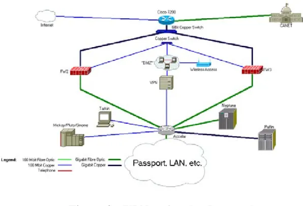
3.2 Network Architecture
The internal network structure at IOT consists of a number of sub-nets, each with a different function depending on the needs of the employees. Most of the research work including data acquisition and manipulation is done through a cluster of machines running the OpenVMS operating system. The cluster consists of five servers named Mickey, Pluto, Gnome, Gecko and Golem. Regular everyday network usage is done through a Windows network, hosted on two servers called Knarr and Karfe. There also exists a Unix network, with servers such as Neptune, where most numerical simulations and the like are done. As well, there is a SUN stack used for data storage called Puffin and a Beowulf cluster for CPU-intensive processes.
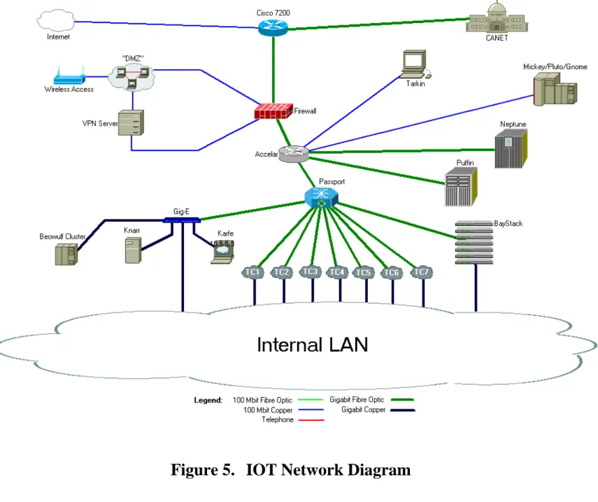
The PC’s and workstations in the network connect to these servers through a mostly 100Mbit switched network on a 1Gbit backbone through a series of 7 small rooms distributed throughout the building called Telecommunications Closets (TC’s). The TC connections all come back to the main computer room, and connect through a Passport fibre switch. Also connected to the Passport is a Gig-E switch, which provides network access to Knarr, Karfe and the Beowulf cluster, along with providing high-speed network connection to a select group of users who require the extra bandwidth. Also connected to the Passport is a BayStack switch, which provides dial-up network access though a pool of modems.
Working backwards from the Passport there is an Accelar device that is used for routing. The Accelar contains 4 fibre modules along with a number of copper modules. Currently the fibre modules connect to the Passport, Neptune, Puffin, and DarkBlue, the firewall machine. There are also copper connections from the Accelar to the VMS servers
Mickey, Pluto, and Gnome, as well as a link to the Debian Linux based system Tarkin, the IOT network intrusion system. Because all of the outside network traffic passing through the firewall must then pass through the Accelar, Tarkin can screen it all. Tarkin could be considered a “last line of defense”, as traffic that is allowed through the firewall is then “sniffed” by Tarkin before proceeding to the inner workings of the network. Tarkin currently runs the Snort intrusion detection software package.
Moving back up along the communication lines, we reach the actual firewall machine, DarkBlue. DarkBlue is running the FreeBSD operating system along with the IPFW software firewall package. This setup will be discussed further in later chapters. DarkBlue has 4 network interfaces, two fibre and two copper. One fibre interface connects to the Accelar, and all traffic to the local network must pass through here. The other fibre interface connects to a Cisco 7200 router, which routes traffic from the Internet and the Canadian government’s CANET destined for our network. The two copper interfaces connect our “Demilitarized Zone” and our Virtual Private Network (VPN) server. A wireless access point is connected along this segment as well. The two copper interfaces are set up such that traffic from the DMZ cannot access the inner network from the top interface; it can only enter through the interface connected to the inside interface of the VPN server. This has the effect of limiting access to the network from the wireless access point while still allowing Internet access. In order to access the LAN from the wireless access point, one must have a VPN client on their local machine and log in through there. This extra level of security between the outside world and the IOT network helps keep the confidential materials housed on the servers safe.
All the connections described above can be viewed on Figure 5, which is a diagram of the IOT network topography. It has been partially adapted from a diagram made by the Computer Systems group’s previous work term student.
3.3 Plan for Firewall Upgrade
The scope of the project detailed in this report is to design and implement a method of replacing the DarkBlue firewall machine with a dual-firewall system of the newer machines FW2 and FW3. In order to accomplish this, a number of proposals were designed and debated on the basis of cost, maintainability, ease of implementation, and security. Four of these proposals will be discussed in the following chapter.
4 P
ROPOSED
I
MPLEMENTATION
4.1 Introduction
There are multitudes of ways in which the two firewalls can be connected, but the chosen implementation must be one that balances cost, security, accessibility and reliability. As such, in this chapter four different possible orientations will be discussed along with each proposal’s various pros and cons.
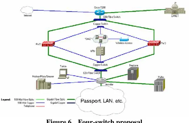
4.2 Proposal 1: Four Switches
It would be very simple to take the four current connections to DarkBlue and send them each through a switch and on to the corresponding interfaces on the two firewalls, as seen in Figure 6. This would require an additional 2 Gigabit fibre optic switches and two 100 Mbit copper switches. There are two unused 100 Mbit copper switches on hand at IOT, so the only additional cost incurred would be the cost of two Gigabit fibre optic switches. However, this cost is a substantial one. In order to provide the fibre optic transfer speeds currently in place, a switch on the order of the Accelar 1100 would be needed along with fibre modules. Switches of this magnitude alone can cost upwards of $30 000. Because of this prohibitive cost, this option is not truly viable.
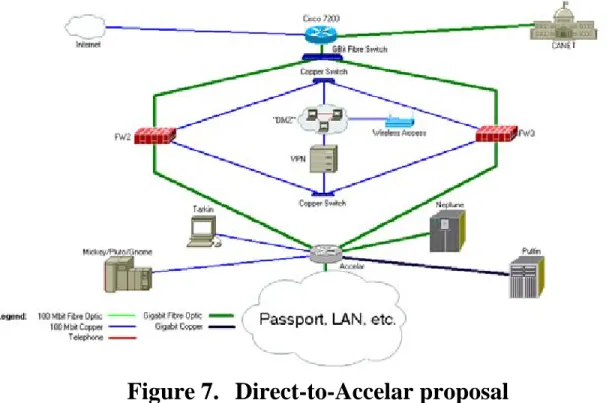
4.3 Proposal 2: Direct Fibre to Accelar
It is possible to eliminate the need for one fibre switch very easily. The Accelar has four fibre ports, which currently go to DarkBlue, Neptune, Puffin, and the Passport. The Puffin Gigabit fibre link could easily be switched over to a copper link into the Accelar, which would leave one fibre port open. The second firewall could make use of this port, as seen in Figure 7. However, this implementation would also require a gigabit fibre switch, which again makes the cost prohibitive.
Figure 7. Direct-to-Accelar proposal
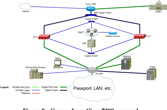
4.4 Proposal 3: Gigabit Copper from Cisco 7200
The Cisco 7200 router has 3 Gigabit-capable modules for connection. Each of these modules can support either fibre optic or copper connections. In the current setup, the connection to CANet and the firewall are on fibre optic while connection to the commercial Internet is on copper. Since the cost of a fibre optic switch has been the prohibitive element in proposals thus far, we can use the Cisco’s dual connection
capabilities to eliminate the need for fibre connection to the firewalls. We can instead use the copper port on the firewall module such that only a gigabit copper switch would be needed, which greatly reduces the cost as there is such a device on hand. The loss of the fibre optic performance is minute compared to the cost saved by using the copper. Such a setup is pictured in Figure 8.
Figure 8. Copper from Cisco 7200 proposal
4.5 Proposal 4: VPN Direct to Accelar
Another idea to limit the amount of equipment needed to implement the dual firewall would be to eliminate the copper switch and connection from the inside interface of the VPN and connect this interface directly to the Accelar, bypassing the inside connection to the firewall. Since the current firewall configuration and rule set does not filter traffic coming from the inside of the VPN, no functionality would be lost from making this connection. There would be one less switch required, and the firewall machines would only need three interfaces each instead of four. However this would come with a trade-off with respect to security. Even though the firewall does not filter traffic from the inside VPN interface, it is “bad style” to open up a pathway to the internal network that does not have to physically pass through the firewall, as this design would introduce. For instance, anybody connecting through the wireless access point and then logging onto the VPN server would not have to pass through the firewall to access the inside of the IOT network. Figure 9 shows this design, and the pathway into the LAN from the wireless can easily be seen to avoid the firewalls. Because the single copper switch and the two extra interfaces are already on hand at IOT, there is not really any benefit to introducing this security flaw.
Figure 9. VPN to Accelar Proposal
4.6 Choice of Proposal
Each of the four proposals discussed above has its advantages and drawbacks. While the first two proposals retain functionality and require little or no time and effort to
implement, the prohibitive cost of the required fibre optic switches make these proposals less attractive. The third and fourth proposals sacrifice the gigabit fibre optic link from the Cisco 7200 router, but have the added bonus of not requiring the expensive switches. This reduction in expense more than makes up for the tiny performance drop that will be experienced through replacing the fibre optic link with copper.
Because the firewall does not filter traffic from the inside interface of the VPN, it would seem to be prudent to eliminate the link from the inside of the VPN back to the firewall. However just because the traffic is not currently filtered does not mean it will never be, and giving up the ability to control this traffic for the modest savings of two copper network interfaces and a 100 Mbit switch is not worth the trade off.
Since the equipment required to implement the third proposal is readily available, it only makes sense to choose proposal 3. In this method, the cost of fibre switches is not
incurred, and less security holes exist because all incoming traffic to the internal network must pass through the firewalls. The fact that the extra equipment required is all on hand at IOT only cements this choice.
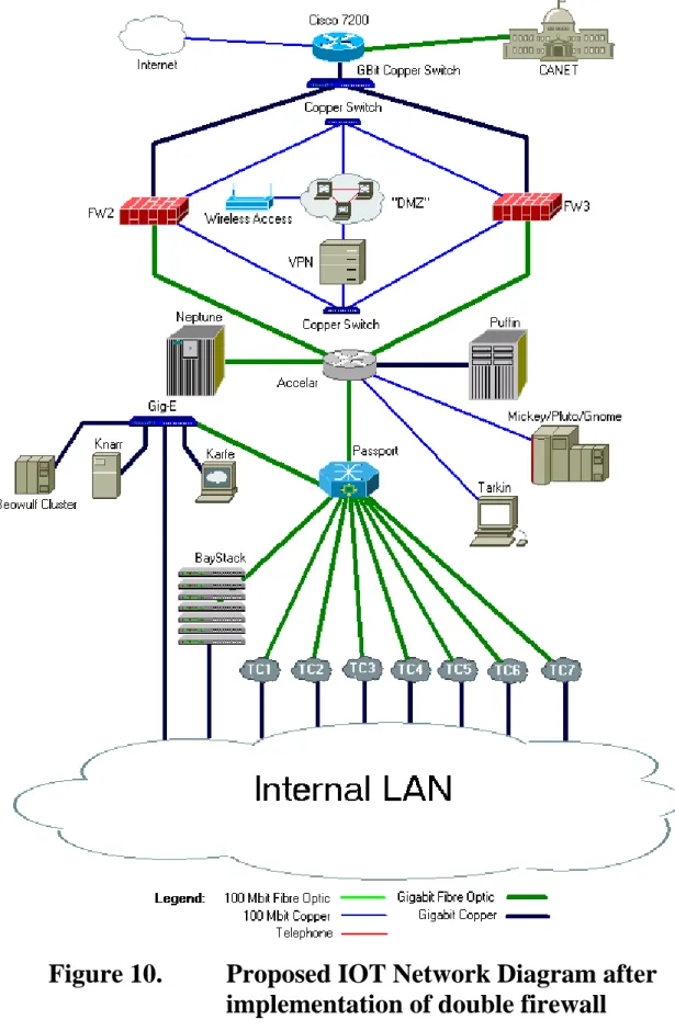
Figure 10 is an updated network drawing showing the implementation of the proposed firewall system. At the completion of the project, this setup should provide the required security for the network as well as the extra stability that comes with the redundancy of the dual firewall system.
Figure 10.
Proposed IOT Network Diagram after
implementation of double firewall
B
IBLIOGRAPHY
How Firewalls Work. Jeff Tyson. 2005. 25 Oct 2005. How Stuff Works. <http://computer.howstuffworks.com/firewall1.htm>.
How Network Address Translation Works. Jeff Tyson. 2005. 2 Nov 2005. How Stuff Works. <http://computer.howstuffworks.com/nat1.htm>.
What is RAID? Mike Neuffer. 2005. 23 Nov 2005. <http://www.staff.uni-mainz.de/neuffer/scsi/what_is_raid.html>.
IPFW. The FreeBSD Documentation Project. 2005. 1 Dec 2050. The FreeBSD Handbook.