an author's https://oatao.univ-toulouse.fr/23753
https://doi.org/10.1109/MWP.2018.8552848
Panasiewicz, Jognes and Britto, Larissa A. D. and Destic, Fabien and Pacheco, Gefeson M. and Rissons, Angélique A photonic QPSK modulation in 2 GHz with an RF signal from a microwave optoelectronic oscillator. (2018) In: 2018 International Topical Meeting on Microwave Photonics (MWP), 22 October 2018 - 25 October 2018 (Toulouse, France).
A photonic QPSK modulation in 2 GHz with an RF
signal from a microwave optoelectronic oscillator
Jognes Panasiewicz∗†, Larissa A. D. Britto∗, Gefeson M. Pacheco∗
∗Instituto Tecnol´ogico de Aeron´autica - ITA
Sao Jos´e dos Campos/SP, Brazil jognes@ita.br
Ang´elique Rissons†, Fabien Destic†
†ISAE-SUPAERO Universit´e de Toulouse
France
Abstract—This article presents a photonic circuit that achieves direct carrier QPSK modulation of an RF signal from an opto-electronic oscillator (OEO) suitable for satellite data transmitter. The circuit was implemented with three Mach-Zehnder optical modulators. One modulator was used to construct an OEO to generate a carrier with a frequency equal to 2.019 GHz. The others two modulators were used to compose the microwave photonic I/Q modulator. The setup initially achieved a data rate of 50 Mbps in a QPSK scheme with an EVM of 7.5%. Using a root-raised-cosine filter, it was possible to reduce the EVM to 5%. The diagrams of the optoelectronic circuit and the modulation measurements are displayed. After the EVM analysis, the modulated signal was demodulated through an actual satellite receiver. Using the demodulator, it was possible to measure the BER and consequently the degradation analysis. The degradation for a bit rate of 100 Mbps was 0.07 dB using the OEO as RF
generator. In this case, the values ofEb/N0and BER were 11.37
dB and 10−7, respectively.
I. INTRODUCTION
Currently, traditional equipment used in satellites such as transponders and data transmitters employs digital modulation. When using digital modulation, the modulation stage of the RF carrier employs in-phase (I) and quadrature (Q) processing to achieve phase shift modulation (M-PSK). In the case of traditional RF circuits, low frequency crystal generation steps, frequency multiplication, amplifiers and filters are required to achieve operating frequency within a desired communication band. In this case, the IQ modulator of some transmitters modulates a digital signal in the S-band, which is then multiplied by the C-band frequency to reach the X-band [1]. Other transmitters directly modulate the digital signal in the X-band [2].
Due to the progressive evolution of Microwave Photonics (MWP) and constant evolution of the optoelectronic compo-nents [3], [4], [5], the European Space Agency (ESA) has been conducting a program of Research and Development to study the application of photonics in satellites since 2002 [6]. Taking advantage of the characteristics of photonic technology and its use in space environment, a circuit that achieves QPSK modulation directly at the carrier microwave frequency was as-sembled and characterized. To achieve the desired microwave carrier an optoelectronic oscillator (OEO) was used, resulting in a photonic system with reduced mass and volume.
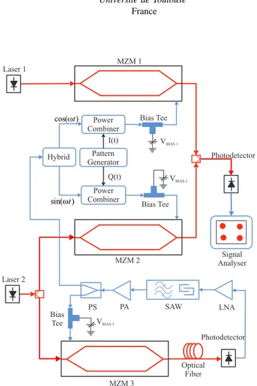
Photodetector Bias Tee MZM 1 I(t) cos(wt) Signal Analyser Laser 1 Pattern Generator Bias Tee MZM 2 Q(t) Hybrid sin(wt) Laser 2 VBIAS 1 VBIAS 2 Power Combiner Power Combiner Photodetector Optical Fiber SAW VBIAS 3 MZM 3 LNA PA PS Bias Tee
Fig. 1. System block diagram of combined circuit.
II. PROPOSED PHOTONIC SYSTEM
The proposed photonic system is composed by an Mi-crowave Photonic Vector Modulator (MPVM), or miMi-crowave photonic I/Q modulator, with the RF frequency generated at an OEO. The MPVM was based on a configuration with two Mach-Zehnder modulators(MZM) arranged in parallel which is similar to an RF phase shifter for a phased array antenna configuration [7], [8], [9]. The MPVM enables digital mod-ulation directly at the desired microwave frequency resulting in a potential increase of the modulation bandwidth due to the characteristics of photonic technology. Thus, the use of an MPVM provides greater RF operation flexibility due to
the tuning capacity of the carrier and reduces the spurious emissions resulting from an upconverter stage.
The circuit used in the OEO was based on the circuit originally proposed by earlier authors [10], [11]. The imple-mented OEO is proposed for use in satellite payload, such as transponders and data transmitters. Thus, it must be small in size and have a greater thermal stability. For this reason, a shorter optical fiber length was used as a delay element as well as a delay element in the RF domain. From this approach, a low phase noise OEO was obtained. The phase noise obtained is lower than the required from the standard ECSS-E-ST-50-05C, which recommends an integrated phase noise lower than 2◦ from a range of 100 Hz to 1 MHz.
Figure 1 shows the block diagram of the implemented setup. Each MZM was driven by a laser source operating in CW mode. The microwave signal generated at the OEO was connected directly in the MPVM input and split by a 90 degree hybrid to generate the cos(wt) and sin(wt) components. The bi-nary data signals, I and Q, were provided by a pseudo random bit sequence (PRBS) generator. Each RF component, cos(wt) and sin(wt), was combined with the data signals, I and Q, by the power combiner. Each power combiner drives an Mach-Zehnder modulator (MZM1 and MZM2) which generates the BPSK modulation. The output from each BPSK modulator was combined through an optical coupler and then inserted into a photodetector, resulting in a QPSK modulated signal at the microwave frequency.
The OEO was implemented using an optical fiber length of 600m. The delay element in the RF domain was obtained using a Surface Acoustic Wave (SAW) band pass filter (BPF). The SAW has a group delay parameter which represents the time it takes for the signal to pass through it. Additionally, the SAW has a low bandwidth, which enables a better frequency selection. In this study, a SAW with a 15 MHz bandwidth was used. In this way, the total delay of the OEO was 3µs with a central frequency of 2.019 GHz.
To control the MZM bias point, and consequently eliminate its nonlinearty, a bias tee was used. This nonlinearity results in an unmodulated carrier peak in the modulated peak which consequently increases the error vector magnitude (EVM). Furthermore, the data stream and the microwave signals were added through a power combiner instead of using the bias tee as in previous studies [12], which in practice limits the data rate.
An interesting alternative scheme of I/Q modulation, and consequently the QPSK, has been implemented, where each component I and Q directly modulates a laser diode [13]. Both optically modulated signals were combined and externally modulated by a microwave signal in an external MZM. The quadrature condition was determined by the fiber length due to its chromatic dispersion. To eliminate the unmodulated peak the addition of a third laser was proposed [14]. As the purpose of this study is space applications, the proposed configuration could be very sensitive to temperature, due to the sensibility of the optical fiber and the addition of a third laser results in greater power consumption. Recently, a polarization division
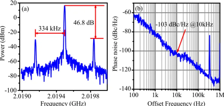
2.0190 2.0194 2.0198 -100 -80 -60 -40 -20 0 20 (a) 334 kHz P o w e r ( d B m ) Frequency (GHz) 46.8 dB 100 1k 10k 100k 1M -140 -120 -100 -80 -60 (b) P h a s e n o i s e ( d B c / H z ) Offset Frequency (Hz) -103 dBc/Hz @10kHz
Fig. 2. The OEO characteristic: (a) electrical spectrum of the generated 2019.5 MHz microwave signal with frequency drift of 1kHz/2 min.; (b) phase noise of the generated microwave signal.
multiplexing-dual parallel MZM (PDM-DPMZM) was used to perform the I/Q modulation without the hybrid [15]. However, the four sub-modulators were all working at the minimum or null point.
III. EXPERIMENTALRESULTS
To show the characteristic of each circuit implemented in this study, the results are divided in three parts. The two MZMs used in the MPVM circuit are LiNbO3 devices with
V π=2.95V while the MZM used in the OEO circuit is one with V π=4.5V . The laser sources are a DFB diode and a Tunable Laser Source where both operating at a wavelength of 1550 nm. The InGaAs photodetector has a 5 GHz bandwidth and a responsivity of 1 A/W. The signals were measured with a Signal and Spectrum Analyser.
A. OEO
The proposed OEO is carried out in accordance with Fig. 1. The optical carrier has an average power of 5mW. The low noise amplifier (LNA) has a noise figure of 0.8 dB with a gain of 25 dB. The SAW has a central frequency of 2017.5 MHz and a 3 dB bandwidth of 15 MHz. The power amplifier (PA) had a gain of 35 dB.
The electrical spectrum is shown in Fig. 2(a) which shows the OEO output with a spacing of 334 kHz between the frequencies and an RF power of 16.8 dBm. The generated 2019.5 MHz microwave signal is within the bandwidth of the SAW filter. It is possible to observe a difference of 46.90 dB between the main and secondary frequency components. These secondary components will be attenuated by the optical link negative gain composed by the two optical modulators and the RF circuit.
The OEO phase noise is shown in Fig. 2(b). A phase noise of -103 dBc/Hz was obtained at an offset of 10 kHz and -118.7 dBc/Hz at an offset of 100 kHz. The integrated phase noise for a range of 100 Hz to 1MHz was 0.64◦. The integrated phase
noise is an important parameter since it takes into account all noise contributions in a given bandwidth.
B. MPVM
Figure 1 shows the circuit combining the MPVM and an OEO with two laser sources. One laser source with a power
of 5 mW was used to drive the MZM1. The other laser source was divided through an optical splitter to drive the MZM2 and the OEO both with a power of 5 mW. Two different pseudo random bit sequences (PRBS) were used to perform the QPSK modulation: a PRBS length of 215
− 1 and of 223− 1 with Root Raised Cosine filter (RRC) using different roll-off factor (RoF) values.
In the initial measurements the data rate was gradually increased in order to verify the system response. It was ob-served that as the data rate was increased, the modulated signal decreased and became distorted with an unmodulated peak appearing in the modulated signal. It was observed that a bias voltage adjustment could restore the modulated signal output. Thus, for each data rate value the bias level was adjusted and consequently, the modulated signal was recovered.
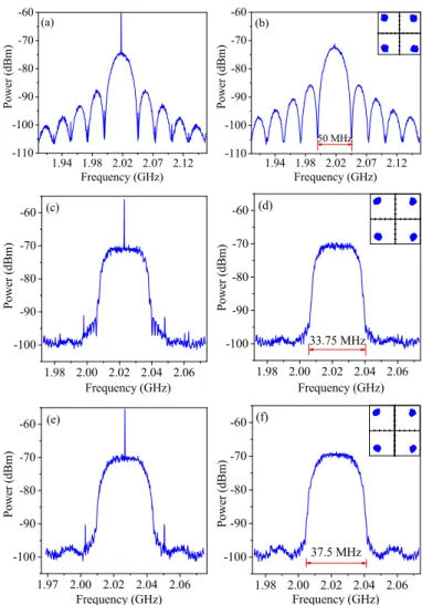
The modulated spectrum with and without RRC filter can be seen in Fig. 3. All the modulated spectrum corresponds to a modulation of 50 Mbps. In Fig. 3(a) and 3(b) shows a QPSK modulation without a RRC filter where the main lobe width is 50 MHz. Fig. 3(a) shows the spectrum before the Vbias adjustment where it is possible to see an unmodulated
peak. When theVbiaswere adjusted to aproximatly 1.5 V the
residual carrier was supressed as can be seen in Fig. 3(b). The inset of Fig. 3(b) shows a constellation diagram where an EVM of 7.5% was obtained. In Fig. 3(c) to 3(f) shows a QPSK modulation with an RRC filter. For Fig. 3(c) and 3(d) the spectrum measurement was carried out with a RoF factor of 0.35. In this way, for a modulation of 50 Mbps, the main lobe width corresponds to 33.75 MHz. The inset of Fig. 3(d) shows a constellation diagram where an EVM of 5% was obtained after the adjustment made in the bias level. For Fig. 3(e) and 3(f) the spectrum measurement was carried out with a RoF factor of 0.5. In this way, for a modulation of 50 Mbps, the main lobe width corresponds to 37.5 MHz. The inset of Fig. 3(f) shows a constellation diagram where an EVM of 5% was obtained after the adjustment made in the bias level. The constellation cannot be observed when the system was not adjusted through the bias level since the the analytical equipment lost the signal in this situation.
Despite the figures were acquired with a bit rate of 50 Mbps, several different values of bit rates were verified. A similar photonic system was proposed earlier by the authors and it was possible to generate a 2.5 GHz RF carrier, which was modulated in BPSK scheme up to a data rate of 2 Mbps [16]. All spectra were obtained without a residual carrier which was suppressed through the adjustment of the bias level of each MZM. A data rate higher than 50 Mbps was not possible due to the limitation of the analytical equipment. In order to verify the modulator degradation and increase the data rate, a demodulation setup which will be explained in the next section was implemented.
C. Degradation analysis
The main idea of this analysis is to verify the modulator performance over an AWGN channel which allows to measure the BER at specific values ofEb/N0. In a degradation analysis,
1.94 1.98 2.02 2.07 2.12 -110 -100 -90 -80 -70 -60 P o w e r ( d B m ) Frequency (GHz) (a) 1.94 1.98 2.02 2.07 2.12 -110 -100 -90 -80 -70 -60 P o w e r ( d B m ) Frequency (GHz) 50 MHz (b) 1.98 2.00 2.02 2.04 2.06 -100 -90 -80 -70 -60 (c) P o w e r ( d B m ) Frequency (GHz) 1.98 2.00 2.02 2.04 2.06 -100 -90 -80 -70 -60 (d) P o w e r ( d B m ) Frequency (GHz) 33.75 MHz 1.97 2.00 2.02 2.04 2.06 -100 -90 -80 -70 -60 (e) P o w e r ( d B m ) Frequency (GHz) 1.98 2.00 2.02 2.04 2.06 -100 -90 -80 -70 -60 (f) Frequency (GHz) 37.5 MHz P o w e r ( d B m )
Fig. 3. QPSK 50 Mbps spectra before (left) and after Vbias adjustement (right): (a) without RRC filter, before Vbias adjustment; (b) without RRC filter, Vbiasset to 1.5 V; (c) RRC filter ROF=0.35, before Vbiasadjustment; (d) RRC filter ROF=0.35, Vbiasset to 1.5 V ; (e) RRC filter ROF=0.5, before Vbiasadjustment; (f) RRC filter ROF=0.5, Vbiasset to 1.5V.
the noise source level is increased step by step in order to obtain a BER for a specific values of Eb/N0. For this
measurement one will use a demodulator and a noise source in order to verify the BER. The demodulator is an actual satellite receiver from Zodiac Data Systems model Cortex HDR XXL capable of demodulating a data rate up to 400 Mbps at an intermediate frequency (IF) of 720 MHz.
In a previous work conduced earlier by the authors, a bit rate of 300 Mbps was achieved using an RF generator [17]. In turn, the degradation analysis was performed for a bit rate of 100 Mbps. For a setup of Eb/N0 = 11.3 dB the measured BER
was 1.25206 × 10⁻⁷ instead of the theoretical BER of 1.10−7,
which corresponds to anEb/N0= 11.24 dB. As a result, the
degradation was 11.3 − 11.24 = 0.06 dB. This result indicates that the transmitter has to provide anEb/N0 = 11.36 dB in
order to meet the same BER of 1 × 10⁻⁷.
The several BER measures earlier obtained using the RF generator will be compared with the BER measures using the OEO. In the same way, for an Eb/N0 = 11.3 dB the
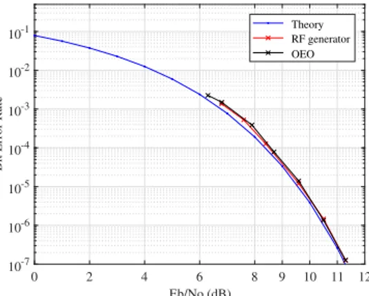
0 2 4 6 8 9 10 11 12 Eb/No (dB) 10-7 10-6 10-5 10-4 10-3 10-2 10-1
Bit Error Rate
Theory RF generator OEO
Fig. 4. Theoretical and measured BER values.
measured BER was 1.26915 × 10⁻⁷, which corresponds to an
Eb/N0 = 11.23 dB. As a result, the degradation was 0.07
dB. This measure was made in 7 points of the BER curve. Figure 4 shows the theoretical BER curve compared with the measured values using an RF generator and the OEO.
As one can see, Figure 4 shows that the theoretical curve is very close to the BER measurements. An important point is the performance of the OEO. Due to its low phase noise characteristic, the BER curve obtained using the OEO is very close to the BER curve using the RF generator. The RF generator used in this measurement has an integrated phase noise of 0.1◦ for a range of 100 Hz to 1 MHz. This is an
important result since it shows that a long fiber length is not necessary to achieve a low phase noise OEO signal able to be modulated.
IV. CONCLUSION
This study presents a direct digital modulation at the carrier microwave frequency based on an optoelectronic oscillator and a microwave photonic vector modulator suitable for satellite data transmitter. The photonic scheme was composed by a microwave photonic I/Q modulator using an RF signal from an optoelectronic oscillator (OEO). The adjustment of the MZM bias level for each bit rate, permitted control the unmodulated peak and consequently suppressed the residual carrier. As a result, the photonic system enables one to reach higher data rates with better stability and modulated signal quality. The first measurements achieved a data rate of 50 Mbps in a QPSK scheme with an EVM of 7.5%. Using an RRC filter, it was possible to reduce the EVM to 5%. In addition, the modulated signal was demodulated through an actual satellite receiver to measure the BER. A bit rate of 300 Mbps was achieved. The Eb/N0 for a BER=10−7 was 11.37 dB at a bit rate of 100
Mbps using the OEO as RF generator.
The results described in this study enables one to see microwave photonics as key technology for near future satellite developments.
ACKNOWLEDGMENT
This work was supported by National Institute for Space Research (INPE/Brazil).
REFERENCES
[1] I. Tosetto, L. Cividanes, B. Santos, L. Silva, and R. Ara´ujo, “Transmissor QPSK em Banda X para Aplicac¸˜ao Espacial,” XXV Simp´osio Brasileiro
de Telecomunicac¸˜oes, 2007.
[2] N. Cartier, C. Flament, S. Albinet, J. Oster, H. Buret, and G. Lesthievent, “X-band high data rate trellis coded 8PSK transmitter for earth obser-vation satellite data transmission,” in Microwave Conference, 2001. 31st
European. IEEE, Sept 2001, pp. 1–4.
[3] J. Capmany and D. Novak, “Microwave photonics combines two worlds,” Nature photonics, vol. 1, no. 6, pp. 319–330, 2007.
[4] J. Yao, “Microwave photonics,” Journal of Lightwave Technology, vol. 27, no. 3, pp. 314–335, Feb 2009.
[5] V. J. Urick, K. J. Williams, and J. D. McKinney, Fundamentals of
microwave photonics. John Wiley & Sons, 2015, vol. 1.
[6] N. Karafolas, J. M. P. Armengol, and I. Mckenzie, “Introducing photon-ics in spacecraft engineering: ESA’s strategic approach,” in Aerospace
conference. IEEE, 2009, pp. 1–15.
[7] J. Coward, T. K. Yee, C. Chalfant, and P. Chang, “A photonic integrated-optic RF phase shifter for phased array antenna beam-forming applica-tions,” Journal of Lightwave Technology, vol. 11, no. 12, pp. 2201–2205, 1993.
[8] S. Winnall, A. Lindsay, and G. Knight, “A wide-band microwave pho-tonic phase and frequency shifter,” Microwave Theory and Techniques,
IEEE Transactions on, vol. 45, no. 6, pp. 1003–1006, 1997.
[9] E. H. W. Chan, W. Zhang, and R. A. Minasian, “Photonic RF phase shifter based on optical carrier and RF modulation sidebands amplitude and phase control,” Journal of Lightwave Technology, vol. 30, no. 23, pp. 3672–3678, Dec 2012.
[10] X. S. Yao and L. Maleki, “Optoelectronic microwave oscillator,” J. Opt.
Soc. Am. B, vol. 13, no. 8, pp. 1725–1735, Aug 1996.
[11] L. Maleki, “Sources: the optoelectronic oscillator,” Nature Photonics, vol. 5, no. 12, p. 728, 2011.
[12] W. Jemison, A. Kreuzberger, and E. Funk, “Microwave photonic vector modulator for high-speed wireless digital communications,” Microwave
and Wireless Components Letters, IEEE, vol. 12, no. 4, pp. 125–127,
2002.
[13] M. A. Piqueras, B. Vidal, J. L. Corral, V. Polo, A. Martinez, and J. Marti, “Direct photonic generation of electrical vector modulations at microwave/millimeter-wave frequencies,” IEEE Photonics Technology
Letters, vol. 17, no. 9, pp. 1947–1949, Sept 2005.
[14] R. Sambaraju, J. L. Corral, J. Palac´ı, V. Polo, and J. Mart´ı, “Perfor-mance analysis of photonic vector modulation techniques for Multi-Gb/s wireless links,” Journal of Lightwave Technology, vol. 26, no. 15, pp. 2684–2691, 2008.
[15] Y. Gao, A. Wen, W. Jiang, Y. Fan, D. Zhou, and Y. He, “Wideband photonic microwave SSB Up-Converter and I/Q modulator,” Journal of
Lightwave Technology, vol. 35, no. 18, pp. 4023–4032, 2017.
[16] J. Panasiewicz and G. M. Pacheco, “A photonic BPSK modulation with 2.5 GHz RF signal from a microwave optoelectronic oscillator,” in
Microwave and Optoelectronics Conference (IMOC), 2015 SBMO/IEEE
MTT-S International. IEEE, 2015, pp. 1–4.
[17] J. Panasiewicz, L. A. D. Britto, and G. M. Pacheco, “300 Mbps photonic QPSK modulator for space applications,” in 2017 Progress
In Electromagnetics Research Symposium - Spring (PIERS), May 2017,