HAL Id: inria-00350294
https://hal.inria.fr/inria-00350294
Submitted on 6 Jan 2009
HAL is a multi-disciplinary open access
archive for the deposit and dissemination of
sci-entific research documents, whether they are
pub-lished or not. The documents may come from
teaching and research institutions in France or
abroad, or from public or private research centers.
L’archive ouverte pluridisciplinaire HAL, est
destinée au dépôt et à la diffusion de documents
scientifiques de niveau recherche, publiés ou non,
émanant des établissements d’enseignement et de
recherche français ou étrangers, des laboratoires
publics ou privés.
objects
K. Kapellos, François Chaumette, M. Vergauwen, A. Rusconi, L. Joudrier
To cite this version:
K. Kapellos, François Chaumette, M. Vergauwen, A. Rusconi, L. Joudrier. VIMANCO: Vision
manip-ulation of non-cooperative objects. 9th ESA Workshop on Advanced Space Technologies for Robotics
and Automation, ASTRA 2006., 2006, Noordwijk, The Netherlands, France. pp.279-286.
�inria-00350294�
Konstantinos KAPELLOS(1), Francois CHAUMETTE(2), Maarten VERGAUWEN(3), Andrea RUSCONI(4), Luc JOUDRIER(5)
(1)TRASYS Space, Terhulpsesteenweg 6 C, B-1560 Hoeilaart, Belgium
(2)IRISA/INRIA Rennes, Campus de Beaulieu, 35 042 Rennes-cedex, France
(3) K.U.Leuven - ESAT-PSI, Kasteelpark Arenberg 10, B-3001 Heverlee, Belgium
GALILEO AVIONICA, Via Montefeltro, 8, 20156 Milano, Italy [email protected]
(5)ESA, ESTEC, Keplerlaan 1, 2200 AG Noordwijk, The NetherlandsLuc.
INTRODUCTION
This paper presents the work performed in the context of the VIMANCO on-going project. It has the objective of improving the autonomy, safety and robustness of robotics system using vision. Vision is certainly the most adequate exteroceptive sensor to deal with complex and varying environments and for manipulation tasks of non cooperative objects. The approach we propose is based on an up-to-date recognition and 3D tracking method that features many advantages with respect to other approaches. First of all, it allows to determine if a known object is visible on only one image. It also allows to compute its pose and to track it in real time along the image sequence acquired by the camera, even in the presence of varying lighting conditions, partial occlusions, and aspects changes. The robustness of the proposed method has been achieved by combining an efficient low level image processing step, statistical techniques to take into account potential outliers, and a formulation of the registration step as a closed loop minimization scheme. This approach is valid if only one camera observes the object, but can also be applied to a multi-cameras system. Finally, this approach provides all the necessary data for the manipulation of non cooperative objects using the general formalism of visual servoing, which is a closed loop control scheme on visual data expressed either in the image, or in 3D, or even in both spaces simultaneously. This formalism can be applied whatever the vision sensor configuration (one or several cameras) with respect to the robot arms (eye-in-hand or eye-to-hand systems).
VISION BASED APPROACH IN ROBOTICS
Exteroperceptive sensors are more and more frequently included in robotic systems, and by definition, provide information about the environment in which they fare located. Their use is obviously essential as soon as tasks have to be performed in non perfectly rigid or known environments. They also allow potential errors or inaccuracies to be identified in the definition of geometric, and therefore kinematic, models for robot manipulators. As regards perception, proximetric sensors provide information about the distance to the closest objects. They are therefore particularly well adapted to obstacle avoidance tasks. Computer vision and range finding systems play a particular role since they can be used either for location, navigation or scanning needs.
For a long time, 3D reconstruction was considered as an essential, independent prerequisite for robot motion generation modules in a non perfectly known environment. With computer vision, this requirement, which was fully justified by the enormously expensive computation times required by image processing algorithms, has given rise to much useful research, in particular in the stereo-vision field. Over the last fifteen years, technological and algorithmic advances have allowed perception and action to be more closely linked, by directly integrating the measurements provided by a vision system in closed-loop control laws applied to extracted visual information. This approach, uses the information provided by one or several cameras in order to control the motions of a robotic system. By controlling between one and all the n degrees of freedom of a system, we can carry out a great number of system positioning tasks within its environment, or mobile object tracking. Whatever the sensor configuration, which can vary from one on-board camera to several free-standing cameras, the aim is to select the best set of measurements k, allowing control of the m desired degrees of freedom, and to elaborate a control law so that these measurements s(t) reach a desired value s*, which can define the
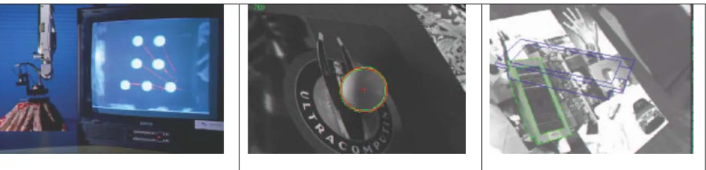
correct implementation of the task. The aim may also be to follow a trajectory s*(t). The control principle is thus to regulate the error vector s(t) – s*(t) so that it equals zero and remains at that value. The choice of the visual feature is function of the task to be achieved. It can be pure 2D information such as coordinates of points, lines, etc or 3D information such as the location of the object in the camera frame. Figure 1 shows various example of visual features used in visual servoing. Our approach is then different from a classical look and move method where the object is localized in the image and where the robot is moved using only this information. Such approach is not robust to calibration errors or to modification of the environment. In visual servoing since visual feature s and then the control law are computed for each new image acquired by the camera the object is not necessarily motionless and the robot may overcome partial modification of the environment during the execution of the task. Furthermore when the task is defined in the image space, only a rough calibration of the system is required.
Figure 1: Examples of visual features used in visual servoing
For many years, visual servoing techniques could only be applied to very simple objects (generally providing binary images), owing to the very slow processing speed for complex image. Advances in algorithmics, in particular in the field of the motion analysis, and more especially the enormous gains in computational power, now allow us to consider real applications running at speeds close to video rate.
BACKGROUND, OBJECTIVES AND OVERALL APPROACH
Future Space Automation and Robotics applications require the use of vision to perform their calibration and the required precise interactions with the environment. Consequently, vision is compulsory to increase the autonomy of the space robotics agents. It could be used for many robotic space applications such as external robotics (EUROBOT), internal robotics (PAT) geo-servicing (ROGER), robotics building of orbital/planetary infrastructures (ESA Exploration Program).
The VIMANCO activity is mainly targeted to EUROBOT, whose purpose is to prepare and assist EVAs on the International Space Station. A typical scenario for the EUROBOT is to place an APFR (Adjustable Portable Foot Restraint) at given locations on the ISS. This involves walking on the handrails and insert the APFR into a specific fixture called a WIF. Another task example is to get the tools necessary for the Astronauts EVAs and bring them back into the EVA Tools Storage Device (ETSD), saving a lot of time for the astronauts. In this context, vision is an enabling technology both for the autonomy and the safety of EUROBOT:
- First, although the positions of the handrails and fixtures are well known, there will be some inaccuracy in the placement of the robot, increasing with movements. Vision processing of images would allow the EUROBOT to know the precise positions of the objects to grasp and where to insert or place them. This is a prerequisite to perform the grasping or insertion task itself.
- Second, object recognition would provide the EUROBOT with the ability to check the environment with respect to its a priori knowledge and detect discrepancies. Extending this concept, it would allow the EUROBOT to “know” position of astronauts with respect to itself, representing very valuable information for advanced safety functionalities.
The European Robotic Arm (ERA) already performs insertion tasks using vision, however, it requires a specific visual target to process the position of the objects to grasp. In the case of the EUROBOT, it is not possible to put a target on
every single object. Vision has therefore to cope with non-cooperative objects, i.e. objects that are not equipped with optical markers.
The use of vision in space has to tackle several specific problems and in particular the extreme light difference in images. This means that direct sunlight makes objects appear very bright while shadows are totally dark. Vision algorithms must be very robust in coping with effect of shadows moving in the imaged scene to allow safe and stable manipulation at anytime. Another major space problem is lack of computing power for processing images. Resource (i.e. energy, volume, mass) and environmental constraints (i.e. thermal dissipation, radiation compatibility) limit performance of computers that may be used in space.
ESA has performed some R&D activities on computer vision in the past. “Stereovision” in 1994 and “Computer Vision for Intervention on Non-Cooperating Objects” between 1996 and 1999 have explored stereovision and monocular vision. Advanced functionalities were demonstrated but computing capabilities lead to very slow processing and results where not directly applied to robot manipulation but more to the Geostationary Space Vehicle Servicing (GSVS). The culminating activity has been in 1999 “VIABLE” which provided in-flight demonstration of manipulation with vision processing on ETS-VII. During this mission, the processing was however performed on ground; it allowed the robot calibration and features recognition, helping the operators on ground. However specific targets were also involved. In this framework, the main objectives of the VIMANCO activity are first, to define a Vision System Architecture applicable to EUROBOT taking into account the characteristics of the EUROBOT environment and the applicability of the vision techniques to the EUROBOT operations, second to implement a Vision Software Library allowing Vision Control for Space Robots and finally to breadboard the specific HW/SW and to demonstrate it on the ESTEC EUROBOT testbed.
Figure 2: a) For Vision Based Manipulation of a non-cooperative object three steps are required: object recognition, object tracking and visual servoing b) Global VIMANCO system architecture
To meet the Vision Control objectives, various step are then required: first the object of interest have to be detected and recognized in the image acquired by the camera. This recognition step must also provide a coarse localization of the object in both 2D and 3D with respect to the camera. Usually this recognition step is time consuming and the result of the localization is not precise enough to be considered for controlling the robot. Therefore we propose to consider a tracking process. Once the object is known, it is possible to track it, over frames and at video rate, using 3D model-based tracking algorithms. These algorithms can use a unique camera but can also consider stereo with small or wide baseline. Finally the output of this algorithm (precise 2D and 3D localization) can be used to control the movement of the robot according to a predefined task. We now describe the three different steps.
- The Vision System. It consists of a stereo pair of cameras attached on a mechanical support and two independent cameras. The stereo camera and each of the two independent cameras dispose an illumination device.
- The Vision System Simulator. It is a 3D graphic tool used to reconstruct the robotic system and its environment to produce virtual images. It simulates as faithful as possible the Vision System mounted on the targeted robotic system.
- The Vision Processing and Object Recognition Library. It implements all functionality needed for Object Recognition, Object Tracking and Visual Servoing. It provides also the means to control their execution and to communicate with the other systems.
- The A&R Simulator. It replaces the robot controller functionality that is needed to validate and demonstrate the whole approach. In real operations the A&R Simulator is replaced by the corresponding A&R Controller.
- The Control Station. It provides the HMIs that allow the operator to run the VIMANCO simulations. It allows activating Actions/Tasks on the A&R Simulator, to configure, monitor and control the Vision System Simulator and to visualise the acquired images.
OBJECT RECOGNITION
The goal of Object recognition is, as clearly stated in the name, the art of finding back specific objects when seen in new situations or different images. It is a subject that has been studied in computer vision since its early days (about fifty years ago). Most systems in those days worked rather ad-hoc on simplified objects such as polygons and polyhedrons. The research community has come a long way since then. In general the task of recognizing an object is made difficult because of the possible variability of the camera’s internal parameters, its position and orientation, the illumination conditions and even the constellation of the visible objects.
Researchers divide object recognition methods between model-based and appearance-based. In the model-based paradigm, the object is represented by a 3D model of its shape. Recognition of a test image amounts to evaluating if it could be a projection of the model. This evaluation tries to find the object pose which would generate the features observed in the image (typically line segments). Model-based approaches have fallen out of favour mostly because it is impractical to provide the 3D model to the system, especially for complex-shaped objects. Moreover, it is inherently difficult to interpret geometric features of the test image as projections of a 3D model, in particular when the ambition is to distinguish among many objects. The philosophy of appearance-based methods differs sharply from the model-based one, and can be summarized as ’just images’. The idea is to model objects from one or more images, without resorting to any 3D model. There are two main kinds of appearance-based approaches: global and local. Global methods build an object representation by integrating information over the entire image. Famous examples are the color histogram, or representations of contours, like the more recent ’shape-contexts’ and ’shock-graphs’. Another, equally important global approach is the one that employs ’eigenimages’. A number of full images, taken from many different viewpoints, are injected into a PCA, so as to obtain a small number of ’eigenimages’ capturing most of the appearance variation. The object’s multiview appearance becomes a low-dimensional manifold into the ’eigenspace’ spanned by the eigenimages. Recognition occurs by projecting the test image into a point in the eigenspace and finding the closest manifold.
Unfortunately, any global representation is very sensitive to background clutter in the test image and to partial occlusion of the object. Therefore, global methods only consider test images without background, or necessitate a prior segmentation, a task which has proven extremely difficult, if not impossible. As additional limitation, robustness to large viewpoint changes between the model and test image is hard to achieve, because the global object appearance varies in a complex and unpredictable way (the object’s geometry is unknown). Local methods counter the problems caused by clutter and occlusion by decomposing an image in a collection of relatively small elements, called local features. Since these features are detected based only on local information, occlusion of part of the object does not affect features in the visible part. Moreover, clutter in the test image only result in additional spurious features, without compromising the ones on the object. During recognition, features are detected in the test image, and put in correspondence with the ones from the model image(s). Usually, an additional stage verifies the coherence of the spatial arrangements of matched features, trying to reject incorrect matches and to compute a global score to be used as recognition criteria (typically the number of verified correspondences). Several kinds of local features have been proposed, including edge segments, local contour groups and very small multicolored neighbourhoods.
- During the mission preparation phase, the off-line training performed in which the objects to be recognized are modelled using features and their corresponding feature descriptors and 3D coordinates
- During operations, the on-line object recognition is based on the same procedure of feature extraction and description and an additional feature matching and verification step.
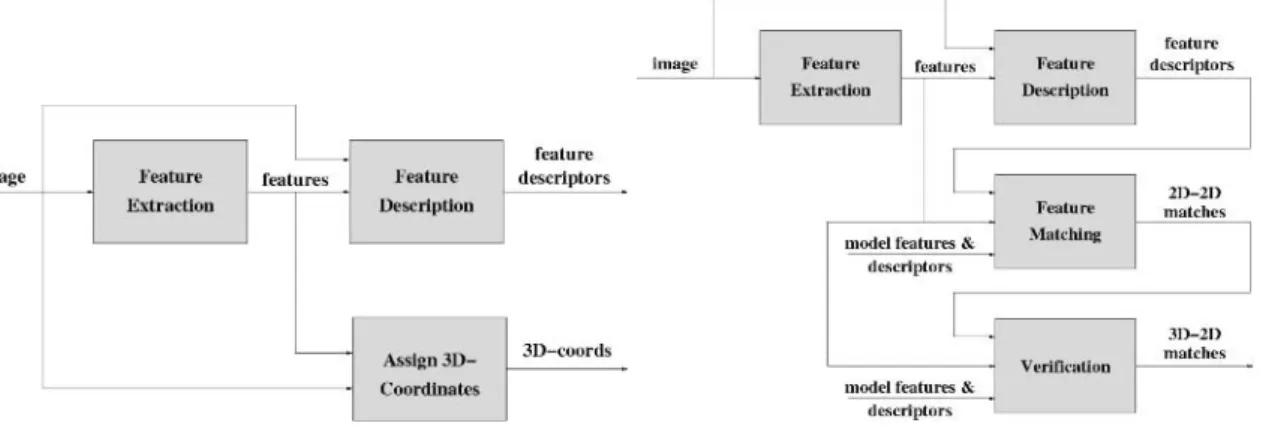
During the off-line training the Object Recognition component describes the objects to be recognized using local invariant features. A specific application with a GUI front-end is employed for this. The algorithm and corresponding data flow of this application are shown in Figure 3a.
Figure 3: a) Object Recognition s/s: Off-line training b) Object Recognition s/s: on-line object recognition The input to the system consists of images of the object to be modelled. For every image a set of features is extracted first, using the Feature Extraction component. These will typically be affine invariant or rotation-scale invariant features like MSER, IBR, SIFT or SURF regions. When these features are extracted, a feature descriptor can be computed for each of them. The Feature Description component is used to this end. The output consists of a feature descriptor for each feature, containing the description of this feature.
In order to initialize the camera pose for Object Tracking, 3D-2D correspondences will be computed later. These can be used to compute the camera pose w.r.t. the object. Since feature matching is performed in the images, we need to assign 3D coordinates to every feature. We do so using a specifically dedicated graphical tool to Assign 3D-Coordinates. As depicted in Figure 3a, the data-flow between the 3 components of the off-line training step is straightforward. An image of the object is the only input of the system. The location of the features is an extra input for the description phase. In order to compute the 3D coordinates of the features, a (simplified) 3D model of the object is needed as well. During real operation, the system needs to identify objects in the image or certify their presence. This is the goal of the object recognition phase, implemented in the Object Recognition activity. The data flow diagram of this activity is shown in Figure 3b. We recognize the first two components of this phase. The Feature Extraction and Feature Description components are identical to those in the off-line training phase. Indeed, the first step in recognizing an object in an image consists of locating features in this image and describing these features using the same algorithm as before. The newly found feature descriptors can then be matched to the feature descriptors of the objects in the database. This is done in the Feature Matching component. The result of this component consists of matches between features, i.e. 2D-2D correspondences. These results can contain mismatches, while other (correct) matches might have been missed. This can be ameliorated by the Verification component, which will output its result in the form of matches between 3D coordinates (found by the Assign 3D Coordinates component in the pre-processing phase) and 2D coordinates (of the features extracted in the target image. These 3D-2D correspondences can be used to compute an initialization of the camera pose w.r.t. the object.
The data flow is clear from Figure 3b. Features and feature descriptors are extracted from the target image and are matched to the model features, i.e. the features extracted in the model images during the off-line training phase. The resulting 2D-2D correspondences are checked in the verification step to yield 3D-2D correspondences.
OBJECT TRACKING
Elaboration of object tracking algorithms in image sequences is an important issue for applications related to robot vision based control or visual servoing and more generally for robot vision. A robust extraction and real-time spatio-temporal tracking process of visual cue is indeed one of the keys to success of a visual servoing task. To consider visual servoing this spatial robotics context, it is fundamental to handle “natural” scenes without any fiducial markers but with complex and non cooperative objects in various illumination conditions. The goal of object tracking is then to determine the position in every image acquired by a camera of particular object (which has been previously recognized). This position may be defined in the image space (we then have a 2D tracking algorithm) or in 3D with respect to the camera or to a world frame (we then have a 3D tracking algorithm). Note that when a 3D localization is available, then the 2D position is also available.
Most of the available tracking techniques can be divided into two main classes: feature-based and model-based tracking. The former approach focuses on tracking 2D features such as geometrical primitives (dots(Figure 4a) , points (Figure 4e), segments, circles, : : : ) or object contours (Figure 4b), regions of interest, …. The latter explicitly uses a 3D model of the tracked objects (Figure 4c-d). This second class of methods provides a more robust solution (for example, it can cope with partial occlusion of the objects). The main advantage of the 3D model-based methods is that the knowledge about the scene allows improvement of robustness and performance by being able to predict hidden movement of the object and acts to reduce the effects of outlier data introduced in the tracking process. When a 3D model is available, tracking is closely related to the pose estimation and is then suitable for any visual servoing approach . Another approach may also be considered when the scene is too complex (due, for example, to texture, to the lack of specific object, etc.). It is not based on features extraction and tracking as in the two other cases but on the analysis of the motion in the image sequence. 2D motion computation provides interesting information related to both camera motion and scene structure that can be used within a visual servoing process.
Figure 4: Features tracking in visual servoing experiments (ordered by subjective increasing difficulties) (a) tracking fiducial markers (b) tracking contours (c) 3D model-based tracking within “clean” environment (d) 3D model-based
tracking in cluttered environment (e) tracking points of interest (f) tracking using motion estimation.
In our work 3D model-based tracking is used since it is usually more robust and it is then more suitable for the considered application. Furthermore such algorithm provides both 2D and 3D localization of the tracked object and it is then very suitable for any kind of vision-based control algorithms.
In particular, the Object Tracking component allows the localisation, at video rate, of a given object, by using for each frame one (or more) current image(s) of this object acquired by one (or more) camera(s), a CAD model of the considered object and its previous localisation. The pose estimation is based on the robust virtual visual servoing technique in which the visual features are the distances between the object contour and the current set of extracted points. In practice, a virtual camera is moved from the previously determined pose to a pose where the projected contour of the object matches the set of extracted points. At convergence, the current pose of the camera gives the pose of the object.
The used control law is very similar to the one used in the Visual Servoing component, excepted that a robust estimator is directly included into the control law in order to correctly reject potential outliers and to estimate the pose of the tracked object with a good precision.
Figure 5: a) Object Tracking and b) Visual Servoing components
VISUAL SERVOING
Basically, vision-based robot control or visual servoing techniques consist in using the data provided by one or several cameras in order to control the motions of a dynamic system. Such systems are usually robot arms, or mobile robots, but can also be virtual robots, or even a virtual camera. A large variety of positioning tasks, or mobile target tracking, can be implemented by controlling from one to all the n degrees of freedom of the system. Whatever the sensor configuration, which can vary from one on-board camera on the robot end-effector to several free-standing cameras, a set of k measurements has to be selected at best, allowing controlling the m degrees of freedom desired. A control law has also to be designed so that these measurements s(t) reach a desired value s*, defining a correct realization of the task. A desired trajectory s*(t) can also be tracked. The control principle is thus to regulate to zero the error vector s(t)-s*(t) . With a vision sensor providing 2D measurements, potential visual features are numerous, since as well 2D data (coordinates of feature points in the image, moments, ...) as 3D data provided by a localization algorithm exploiting the extracted 2D features can be considered. It is also possible to combine 2D and 3D visual features to take the advantages of each approach while avoiding their respective drawbacks. Figure 5b illustrates the block diagram of the Visual Servoing algorithm.
If the task is specified as a 3D displacement in the robot end-effector frame (called after the hand), or as a pose between the hand or the camera and the observed object, an accurate calibration of the camera and of the eye-hand pose has to be performed, so that the task can be expressed as an accurate pose to reach between the camera and the object.
A coarse camera and eye-hand calibration is sufficient in the case where the task is specified as a particular position of the object in the image. In practice, this can be obtained using an off-line teaching by showing step where the end-effector is moved once at its desired position with respect to the object and the corresponding image is stored. In that case, the data extracted from the vision sensor will be biased due to the calibration errors, but the robustness of the visual servoing with respect to calibration errors will allow to move accurately the arm so that the final image corresponds to the desired one, ensuring a correct realization of the task.
THE VISION SYSTEM
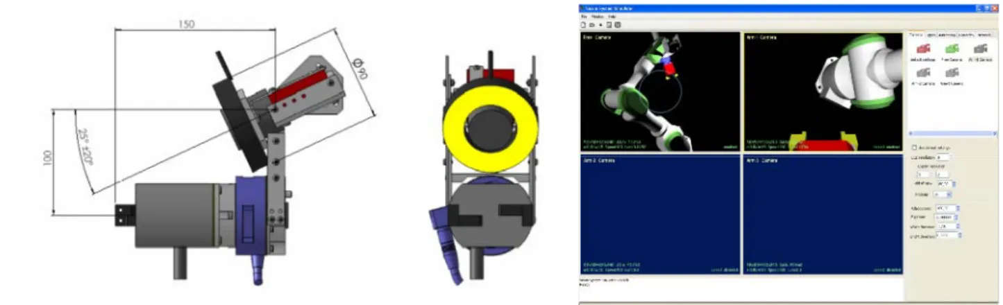
The Vision System supports the characterisation of the object-recognition and the visual servoing algorithms developed in this activity. Since the system is meant as a tool for EUROBOT, the Vision System mimics the EUROBOT setup. We consider a camera-setup as shown in Figure 6: a stereo pair of digital cameras attached on a mechanical support and two independent digital cameras to be attached to the end effector of two of the EUROBOT testbed arms. In order to match as perfectly as possible the ideal illumination characteristics of the cameras, the stereo pair and each independent camera will be provided with an individually regulated illumination sub-system, consisting of hallogen head-lights.
Figure 6: The VIMANCO Arm Camera Vision System
VISION SYSTEM SIMULATOR
The development and the validation of the vision algorithms that implement the previous objectives requires images at each new robot position as input and a robot to execute the required control output. Disposing such a hardware configuration for the development and the first tuning of the algorithms is impracticable since very time consuming: a vision simulator that provides the possibility first to produce realistic virtual images from a synthetic environment and second to control a simulated robot in this environment has been developed and integrated for testing and tuning the vision algorithms.
REFERENCES
[1] B. Espiau, F. Chaumette, and P. Rives. A new approach to visual servoing in robotics. IEEE Trans. on Robotics
and Automation, 8(3):313–326, June 1992.
[2] E. Malis, F. Chaumette, and S. Boudet. 2 1/2 D visual servoing. IEEE Trans. on Robotics and Automation, 15(2):238–250, April 1999.
[3] A.I. Comport, E. Marchand, and F. Chaumette. Robust model-based tracking for robot vision. In IEEE/RSJ Int.
Conf. on Intelligent Robots and Systems, IROS’04, volume 1, pages 692–697, Sendai, Japan, September 2004.
[4] T. Tuytelaars, L. Van-Gool, L. Dhaene, and R. Koch, "Matching affinely invariant regions for visual servoing", Proceedings of the IEEE Conference on Robotics and Automation, pages 1601-1606, 1999.
[5] V. Ferrari, T. Tuytelaars, and L. Van-Gool, "Simultaneous object recognition and segmentation by image exploration" In Proceedings of the European Conference on Computer Vision, 2004.
[6] K. Kapellos, “JET: The DREAMS System” Executive Summary, TRASYS Space, 29/08/2001.
[7] D. Simon, et al., “Computer-aided design of a generic robot controller”, IEEE Trans. Control Sys. Techn., 1993. [8] K. Kapellos et al, “Task Level Specification and Formal Verification of Robotics Control Systems”, Int. J. Sys.
Sci., 1999.