HAL Id: hal-01847804
https://hal.archives-ouvertes.fr/hal-01847804
Submitted on 6 Sep 2018HAL is a multi-disciplinary open access
archive for the deposit and dissemination of sci-entific research documents, whether they are pub-lished or not. The documents may come from teaching and research institutions in France or abroad, or from public or private research centers.
L’archive ouverte pluridisciplinaire HAL, est destinée au dépôt et à la diffusion de documents scientifiques de niveau recherche, publiés ou non, émanant des établissements d’enseignement et de recherche français ou étrangers, des laboratoires publics ou privés.
Size effect in transient thermal fatigue testing and
thermo-mechanical screening of coatings
Gilles Dour, Farid Medjedoub, Gabriel Diaconu, Denis Girardin, Abderrahim
Michrafy, Tahar Loulou, Farhad Rezai-Aria
To cite this version:
Gilles Dour, Farid Medjedoub, Gabriel Diaconu, Denis Girardin, Abderrahim Michrafy, et al.. Size effect in transient thermal fatigue testing and thermo-mechanical screening of coatings. Interna-tional Journal of Microstructure and Materials Properties, Inderscience, 2008, 3 (2-3), pp.311-325. �10.1504/IJMMP.2008.018737�. �hal-01847804�
Size effect in transient thermal fatigue testing and
thermo-mechanical screening of coatings
G. Dour*, F. Medjedoub and G. Diaconu
CROMeP – Ecole Mines Albi 81013 Albi Cedex 09, France E-mail: dourdour@enstimac.fr E-mail: gilles.dour@applusrtd.com.au E-mail: farid.medjedoub-renexter@renault.com E-mail: gabita.diacou@yahoo.com *Corresponding author
D. Girardin
Centre de R&D St. Gobain PAMBP 109, 54 704, Pont à Mousson, France E-mail: Denis.Girardin@saint-gobain.com
A. Michrafy
LGPSD, UMR 2392
CROMeP – Ecole Mines Albi 81013 Albi Cedex 09, France E-mail: michrafy@enstimac.fr
T.M. Loulou
Laboratoire d’Etudes Thermiques Energetiques et Environnement Universite de Bretagne-Sud
B.P. 92116, 56321 LORIENT Cedex, France E-mail: tahar.loulou@univ-ubs.fr
F. Rézaï-Aria
CROMeP – Ecole Mines Albi 81013 Albi Cedex 09, France E-mail: rezai@enstimac.fr
Abstract: In an attempt to bring new ideas to thermal fatigue analysis of
tools, we propose the principle of the two driving forces leading to damage by Thermal Fatigue (TF). After a definition of the two driving forces based on temperature and thermo-mechanical loadings, a procedure for evaluating them for in-service tools is proposed. In order to compare thermo-mechanical
1 Introduction
Forming materials at high temperature is a common process found in industry. Many classical examples can be given, such as permanent die casting, forging, extrusion, glass blowing in dies, glass pressing, etc. The trend in industry seems to be getting more and more applications of hot forming (e.g., deep drawing of martensitic steels), if not using higher temperatures in classical processes (e.g., isothermal forging and high-pressure die casting of copper alloys). The common feature of all the hot-forming processes is that the tools never last forever. Usually the lifetime is limited by the formation of too large or too dense or too deep heat-checking cracks. The criteria determining the end of life of tools can vary extremely from one industrial sector to another. Heat-checking cracks are characterised by a network of cracks on the mating surface of the tools (where contact with the parts occurs). The depth of the cracks is usually limited, although sometimes one or a few of the cracks take the opportunity of some stresses to propagate deeply into the tool. Heat checking is the result of a Thermal Fatigue (TF) phenomenon: the mating surface is heated by the brief contact with the hot part being formed, while the bulk of the tool remains colder. The dilatation of the hot surface of the tool is restricted by the bulk, leading to some thermo-mechanical loadings. Depending on the process and on the tool surface requirements, the lifetime of such tools rank from 10 000 to several 100 000 cycles. It rarely extends to high-cycle fatigue lifetimes. Because tools are expensive and because their lifetime tends to get shorter with higher productivity, the Western industries seeking higher productivity need to improve their tools so that productivity gains will not be lost by higher tools costs. It is the reason why many investigations have been launched
loadings in industrial tools to laboratory specimen, a normalisation of the thermo-mechanical equations is proposed. A size effect in those thermal mechanical problems is justified and used to set an original rule to design transient TF tests. In a second example related to coating tools or bi-materials tools, the concept of thermo-mechanical screening is explained: it corresponds to the optimum combination of materials properties leading to the vanishment of thermal stresses at the mating surface of a tool. An example is given that shows some conditions in which this can happen, depending on the combination of material properties. An example of application is then proposed.
Keywords: hot forming processes; shaping processes; hot work tool steels;
Thermal Fatigue; TF; thermo-mechanical; thermal stresses; heat checking.
Reference to this paper should be made as follows: Dour, G., Medjedoub, F.,
Diaconu, G., Girardin, D., Michrafy, A., Loulou, T.M. and Rézaï-Aria, F. (2008) ‘Size effect in transient thermal fatigue testing and thermo-mechanical screening of coatings’, Int. J. Microstructure and Materials Properties, Vol. 3, Nos. 2/3, pp.311–325.
on the understanding of TF and on the improvement of lifetime of tools. Many TF experiments have been developed in the USA (Benedyck et al., 1970) and more recently in Europe (Jean et al., 1999; Pellizzari et al., 2001; Persson et al., 1999; Siller et al., 2004). American standard tests for foundries are based on the alternative dipping of a specimen in a molten alloy followed by external water spraying (Benedyck et al., 1970). Many materials, particularly tool steels, have been tested. Other investigations took inspiration in such a test with more or less success (Mitterer et al., 2000). The other TF tests conceived are based on the heating of the surface of specimen by an external source of heat such as LASER, inductive heating, etc. The advantage of such techniques is that one can monitor (Persson et al., 1999) the deformation of the tool surface, or control the heating rate of the surface (Medjedoub et al., 2005). Up to now, no clear trends in lifetime extension can be found yet from all these tests when applied to tool steels. Another trend that we can see in industry is the temptation to apply coating on the surface of the tools in order to extend their lifetime. If the effects on chemical interaction are quite certain in high-pressure die casting with PVD coatings, improvement in the TF resistance is not as clear (Persson et al., 2005) depending on the criteria used to define the improvement.
The present paper intends to address both the TF of massive tools and the effect of coatings. The understanding of thermal fatigue is first summarised in the principle of the two driving forces of the damage process under thermal fatigue conditions. In order to improve the design of coating or of thermal fatigue tests, we propose to exploit normalisation techniques to the multiphysical problem of thermo-mechanical loading. It is then used as an example to design a TF test based on the two driving forces principle and to the size effect in thermo-mechanical problems. As a last example, the normalisation technique is applied to bi-material tools. A condition called thermo-mechanical screening (i.e., the condition to reach in order to reduce to zero the thermal stresses at the surface of the tool) is sought when changing the thermo-physical properties of the coating for a given processing condition.
2 The principle of the two driving forces of damage by thermal fatigue
A given tool made of a given material is the centre of a number of loadings. Basically it feels some loadings from its surface and mainly from the surface in contact with the part being produced – the mating surface. The boundary conditions are then essential to understanding the way a tool has to work: sliding of the part and shear stresses, filling of the tool under high pressure and compression stresses, high temperature of the part and thermal stresses. In hot-forming processes the thermal loading is fundamental (Dusserre
et al., 2005). As seen from the tools, the essential thermal loading is the density of
heating power it receives from the mating surface, no matter what the process is. This density is known in the heat transfer community as the heat flux density, measured in W/m2. A common order of magnitude in hot-forming processes is the MW/m2. There
exist other boundary conditions, such as mechanical ones: the pressure felt by the die or the matrix, the tangent loads caused by the friction with the part being produced or restraints caused by the bolting of the tool in a machine. All these, plus the geometry of the tool, are the necessary information one needs to know if ever one intended to understand the working conditions of a tool (e.g., see Dour et al., 2003) for heat flux density measurement). Any numerical FE packages could be used to evaluate the
temperatures and stresses in the tool. In cases where the thermal loading is the main restricting load, one may wonder which behaviour law should be considered for the tool material. To illustrate the difficulty let us imagine two new fresh tools, one hard and the other one soft. The soft tool steel has then a much smaller yield stress compared with the hard tool. Nevertheless most of the other properties are the same: elastic properties, thermal properties, expansion coefficient. The two tools also see the same boundary conditions while in production. As often the lifetime of hot-forming tools range is in the Low Cycle Fatigue category (less than 100 000 cycles), lifetime can be related to plastic deformation (Manson-Coffin analysis) instead of stresses (Basquin analysis). In such a case, comparing the two materials fatigue properties would require that one apply the same plastic deformation to each of the specimen during the test. Because they have different yield stresses, the thermal fatigue test should then be performed at different thermal loadings (higher heat flux for the harder material). This does not reflect what actually happens to the tools when in service: the harder tool is thermally loaded with the same thermal gradients that lead to the same thermo-mechanical loadings, and then to lower plastic deformation than the soft tool. In order to replicate the service conditions, it is better to test the two steels in exactly the same thermal conditions: same temperature, same heat flux density and same geometry. The two materials will then react to the thermal loading according to their own behaviour. This will eventually lead to different TF resistances as the softer steel will deform plastically more than the other one.
The same question arises when one wishes to compare results from several laboratory TF tests. It is obvious the temperature should remain the same in all geometries, because any thermally activated phenomenon strongly depends on it. However, if the same heat flux density were used, the thermal stresses in the two tests would be different, leading necessarily to two different TF lifetimes. If one expects to compare these two tests, something has to remain constant. The previous example of hard and soft steels suggests that the Elastic Body Thermal Stresses (EBTS) would be the parameter to keep constant; it corresponds to the thermal stresses as can be evaluated when considering that the materials is perfectly elastic. The reason behind this choice of EBTS comes from the consideration that the origin of all the stresses and mechanical strain during thermal loading is the incompatibility of thermal expansion when a part is heated or cooled with a non-uniform temperature field. It is well known that the thermal expansion is linked to the lattice bulging of the crystalline network. Any material can accommodate the incompatibility of thermal expansion with another crystalline lattice distortion. This one is called elastic deformation, or Elastic Body (EB) deformation. When it is induced by heterogeneous thermal field, the lattice distortion is what we call EBTS. This EBTS response of the material to thermal heterogeneity is reversible and immediate. However, the EBTS are often high enough to push dislocations to motion, inducing plastic deformation. This second class of response of a material to thermal loadings is evidently irreversible and its kinetics is usually slow and temperature-dependent. As a consequence, the elastic body thermal stresses EBTS and the temperature taken together can be seen as the potential that push materials to transform irreversibly when thermally loaded. With the accumulation of irreversible deformation leading to failure, the couple (T, EBTS) also potentially leads to TF when thermal loads are repeated cyclically. As a consequence, TF tests performed with the same materials can be compared only if the same couple (T, EBTS) is applied to the specimen. Most of the time, T may be the same, but certainly not the EBTS.
3 About the use and the interest of normalisation techniques
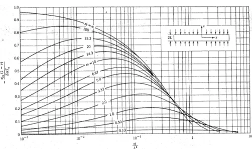
In a multiphysical problem such as the thermo-mechanical problem that is faced by tools, the number of parameters is tremendous. Typically EBTS are controlled by the thermal gradients in the bulk of the tool, which in turn is controlled by the thermal properties (conductivity, diffusivity) and the thermal loading (heat flux density). Of course the expansion coefficient and elastic properties will have their words to say, as well as the geometry of the specimen. Our aim here is to describe the relationship between the thermal loading, material properties and a characteristic dimension of the tool for a simple geometry (e.g., slab or hollow cylinder). Nevertheless the number of parameters remains too large to study the influence of each of them separately. It is necessary to reduce the number of parameters. The best way to do so is to normalise the equations of the problem. Such a normalisation had been performed by Landau and Paschkis (LP, 1957) in the 1950s for a slab dipped in a liquid bath at constant temperature (quenching condition). Figure 1 summarises the whole set of results. The parameters of this problem are: the temperature difference Ta between the bath (constant and set to 0) and the initial
temperature of the slab; the heat transfer coefficient between the slab and the liquid h; the thickness of the slab 2L; the thermal conductivity of the slab materials k; its thermal diffusivity κ; the thermo-elastic properties of the slab materials (Young modulus E, Poisson coefficient ν, thermal expansion α) and time t. When writing the non-transient conduction equation coupled with the thermo-elastic balance equation (EBTS problem), LP managed to reduce the set of seven parameters to four non-dimensional numbers: the Biot number m=hL/k; the normalised time t+=κt/L2 the normalised temperature T+=T/T
a
and the normalised EBTS σ+=–σ/[αET
a/(1–ν)]. Figure 1 shows how the normalised
EBTS σ + evolves with the normalised time t +, as a function of the Biot number m. If one
has to determine the real EBTS for a given slab in some quenching condition, one has just to determine which curve best describes its problem and then to renormalise the EBTS and time parameters.
Figure 1 Tabulation of EBTS in a slab quenched in a liquid pool
Source: Boley and Weiner (1968)
In the problem of tools in hot-forming processes, the problem is slightly different from the LP quenching problem. First of all, the problem is not symmetrical as one face is heated up by contact with the hot part being shaped, and the second face is usually cooled down by a cold fluid (air, water or oil). A second difference is that the temperature of the part being shaped varies during the process (unlike the liquid in the quenching problem of LP), as well as the tool/part heat transfer coefficient. As a consequence, the heat transfer coefficient is not a relevant parameter for the mating surface of the tool. As the key information to describe the thermal loading of a tool remains the heat flux density, we will prefer it to a description with a heat transfer coefficient. The heat flux density usually varies dramatically during the fabrication process. In the following we will model the thermal loading by a step function of the heat flux density characterised by a maximum value φmax and a duration τ. For the back surface of the slab, the liquid cooling is
characterised, like in LP by a heat transfer coefficient h and the temperature of the liquid (set to zero). Taking all this into account, the normalisation of the problem for a 2L-thick slab can be performed with the following set of equations (see Diaconu (2004) and Diaconu and Dour (2001) for the details of the equations):
2 t t L κ + = (1) z z L + = (2) h L h k + = (3) max ( ) ( )t φ t φ φ + + = (4) max ( , ) ( , ) T z t T z t L k φ + + + = (5) max ( , ) ( , ) 1 z t z t L E k σ σ φ α ν + + + = − (6)
where the parameters k, κ, E, α and ν are the same as in the LP problem and z is the coordinate in the slab thickness direction (zero being at the mating face). All the new parameters (noted with +) are dimensionless.
4 Application to thermal fatigue: size effect and towards the design of a TF test
The tabulation performed by LP demonstrates clearly that two slabs of thickness L and L′ (L′ > L) made of the same materials (same E, α and ν) and quenched in the same conditions (same Ta and same h) develop different EBTS. They indeed have a different
Biot number m and m′ (m′ > m). The resulting maximum EBTS will be different with the larger slab being the most stressed, even though the thermal gradients are the same. This effect is hereby named the ‘size effect in EBTS problems’.
Back again to the TF tests for tools, two questions arise from the size effect: How do the results from two TF tests compare if they have been performed on the same geometry but different sizes? How does a TF test result compare to the TF of a real industrial tool, knowing that the dimensions are an order of magnitude different? In order to address these two questions, it is necessary to consider the previous remarks on the driving forces and the normalisation of the problem. When one designs a TF test for transient thermal load, one should try to create on the surface of the lab specimen the same driving forces (Tmax and EBTS σmax) in the same time t as what could be seen in a real industrial tool.
Let us assume that measurements on the industrial tool and numerical simulations provide the necessary information for the most critical area of the tool. It would be easy to reach the same temperature in the same time as for the tool. It is just a matter of adapting the heating power density (inductive heating, IR lamps, etc.) to heat up the specimen at the right rate and to the same temperature. However, there is no warranty that the EBTS will be the same as in the tool. In order to make it for sure, a proper design of the test has to be performed. We have modelled the EBTS in a hollow cylindrical specimen. The heat conduction and the thermo-elastic set of equations is given below:
1 1 0 T T r r r r t ∂ ∂ ∂ ∂ ∂ κ ∂ ⎛ ⎞ − = ⎜ ⎟ ⎝ ⎠ (7) 2 1 1 2 2 1 2 2 2 2 2 1 ( ) 1 ( , ) ( , ) ( , ) (1 ) (1 ) r R rr R R r R E E r t T r t r dr T r t r dr r R R r α α σ ν υ − ⋅ ⋅ = − ⋅ ⋅ − ⋅ ⋅ − − ⋅
∫
−∫
(8) 0 2 1 2 2 2 1 2 2 2 2 1 ( , ) ( , ) ( , ) 1 (1 ) ( ) 1 ( , ) (1 ) r R R R E E r t T r t r dr T r t r r R E T r t r dr R R r θθ α α σ υ υ α ν ⋅ = ⋅ ⋅ − − − ⋅ + ⋅ + ⋅ ⋅ − −∫
∫
(9)where R1 and R2 are the inner and outer radius of the cylinder, respectively. The thickness
Ep is equal to R2-R1.
In the TF test, usually the outer surface is heated up by the application of LASER or by inductive heating with a step-type of heating power. The inner tube is usually cooled down with a flow of fluid. When normalised with the set of Equations (1 to 6), L being replaced by R2 for instance and z being replaced by r, the set of EBTS expression
transforms s into (Dour et al., 2005):
1 2 2 2 2 1 1 1 (1 ) ( , ) ( , ) ( , ) (1 ) 1 rr r Ep Ep Ep r r t r T r t dr r T r t dr r Ep σ + + + + + + + + + + + + + + + + + + + + − − ⎡ − − ⎤ = − ⎢ + ⎥ − − ⎢ ⎥ ⎣
∫
∫
⎦ (10) 1 2 2 2 1 2 1 (1 ) ( , ) ( , ) 1 ( , ) ( , ) Ep r Ep Ep r r t r T r t dr r r T r t dr T r t r θθ σ + + + + + + + + + + + + + + − + + + + + + + + + − − + = + −∫
∫
(11)where Ep+ is the normalised thickness of the cylinder 2 1 2 . R R Ep R += − (12)
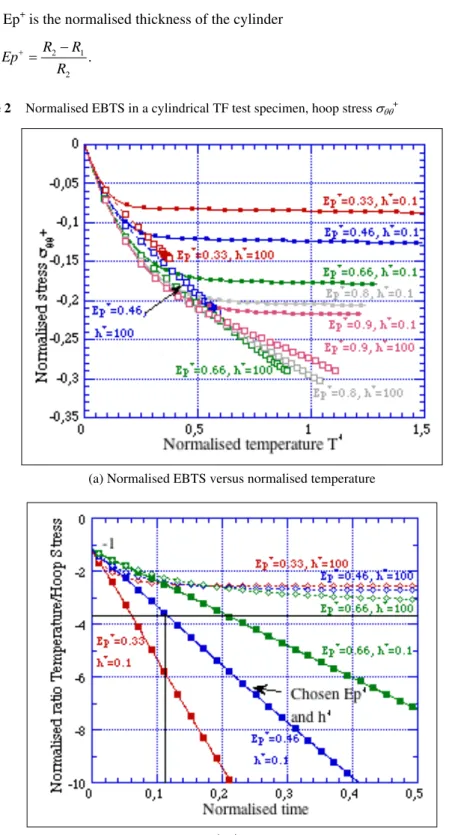
Figure 2 Normalised EBTS in a cylindrical TF test specimen, hoop stress σθθ+
(a) Normalised EBTS versus normalised temperature
Compared to the situation described by LP, the normalised problem has a set of two parameters: the biot number h+ characterising the heat transfer with a cooling liquid in the
inner tube and the normalised thickness Ep+ of the cylinder. Figure 2(a) shows the thermo-mechanical path σ+
θθ versus T+ for the heated surface for cylinders with various Ep+ and h+. Normalised time appears in the chart in the sense that each dot corresponds to a normalised time increment of ∆t+=0.02. It shows in particular that high biot numbers
situation is very different from that with low biot numbers: for large times the low biot numbers converge to a steady EBTS, whereas temperature keeps increasing, which is contrary to a high biot number situation where both stress and temperature tend to converge in the same time to a definite value. Figure 2(b) represents the evolution with time of the ratio between T and EBTS in the normalised form. As expected from the similarity of the curves 2a in the first times, the ratio tends to be 1 for all cases. It is only for longer times that the curves diverge.
The results shown in Figure 2(a) can be used to choose the proper dimensions of the TF test specimen [6]. In order to do so, the following method is proposed:
• Measure or collect information about the material’s key parameters (E, α, ν, κ, k). • It is assumed that the working conditions of the reference tool have been determined.
In particular the maximum EBTS σmax and maximum temperature Tmax are recorded to occur at the time τ.
• From Equations (5) and (6), Equation (13) is obtained. This equation can be applied for r = R2 at the surface of the TF specimen (i.e., r+=1) and for the time τ (the same as identified on the reference tool) when the driving forces must be at their peak values. The non-normalised stresses and temperature should then be Tmax and σmax as identified on the reference tool.
• Identify the ratio T+
maxσθθ+max on the chart in Figure 2(b) (see the horizontal line) using the second member of Equation (8) with the maximum temperature, maximum stresses, and the materials data.
• At that point it is necessary to choose the normalised thickness Ep+ of the tube and the relative heat transfer coefficient h+. Where the chosen curve crosses the horizontal line, the time τ+ reads the normalised time that should be used on the lab specimen to reproduce the real time τ on the industrial tool.
• In order to obtain the same time on the lab specimen as on the actual part, the reference length R2 must satisfy Equation (1), which leads to Equation (15).
• From the chart found in Figure 2a, it is now possible to determine T+
max and σθθ+max at the instant τ+.
• The heat flux density that is needed to perform such a TF test is given by Equation (16) and the power supply that is needed for a tube of length Z is given by Equation (17): ( , ) ( , ) ( , ) 1 ( , ) T r t T r t E r t r t α σ ν σ + + + + + + = − (13) max max max max 1 T T E θθ α σ ν σ + + = − (14)
2 R κ τ τ+ = (15) max max 2 max T k R T φ = + (16) 2 max 2 . P= πR Zφ (17)
If one follows the method step by step, one will be sure that the two driving forces of the TF damage phenomenon will be the same on a lab specimen as on a real tool. This is the necessary condition if one expects to reproduce the same TF and to find comparative results.
5 Application to coatings: the thermo-mechanical screening
In order to improve the wear resistance of tools or to prevent them from corroding or to isolate them thermally, it becomes more and more common to cover tools with a coating. We are not going to discuss the efficiency of the coating with regard to the primal function it probably fulfils. The issue that we consider in the following is the effect that coating has on the EBTS. In other words, the question is: does a coating improve or worsen the EBTS build-up and consequently does it affect the TF resistance of a hot forming tool?
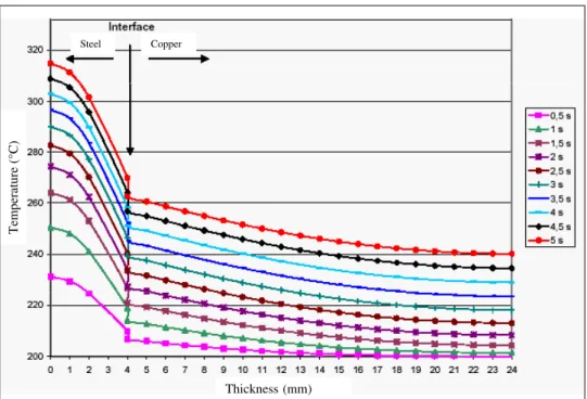
In an attempt to understand these effects, we developed precise semianalytical calculations of the EBTS in a coated cylinder representing the die of centrifugal casting (Diaconu et al., 2005). The hollow cylindrical die is filled with cast iron in the inner radius, while the die rotates at high speed. The molten metal is then forced into contact with the inner radius of the die and solidifies to take the dimensions and the shape of the inner cylinder. Of course the die is heated up from its inner radius and cooled down by water flow at the outer radius. Figure 3(a) shows the temperature field that should develop during casting for a 4 mm thick steel layer coated on a copper substrate (20 mm thick). Copper is well known to be highly thermally conductive. It also has a higher expansion coefficient, but a lower Young modulus than steel has. One can notice that the highly conductive copper shows very little temperature gradients compared to steel. During the heating process, the temperature gap at the interface between the two materials builds up owing to a heat contact resistance (RTC is taken to be 10–5 m2KW–1).
Figure 3(b) shows the resulting hoop EBTS σθθ through the bi-materials die. At the
beginning of the cycle (T uniform at 200°C) the stresses are not null. This is due to the heterogeneous dilatation from 0°C to 200°C of the two materials (0°C being considered here as the temperature of deposition free of stress). The steel (respectively copper) is always in tensile (respectively compressive) stresses at that stage, because it dilates the least (respectively the most). When the thermal loading starts, the coating EBTS tends towards negative values. This means lowering the already tensile stress. The resulting Von Mises stress tends to smaller values at the mating surface, which faces less risk of yielding, and hence of TF failing. However, the interface remains at large stresses.
Figure 3 The temperature and hoop stress fields at different instants for the assembly
steel/copper (for colour please see online version)
(a) Temperature profile in a cylindrical bi-materials die of centrifugal casting
(b) Hoop EBTS profile in a cylindrical bi-materials die of centrifugal casting Thickness (mm) Temperature (° C) Copper Steel Thickness (mm) Hoop EBTS MPa ) Steel Copper Interface
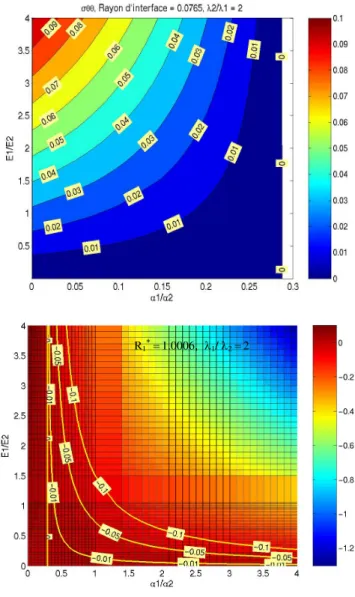
Figure 4 Map of the normalised stress σθθ+ at the mating surface at t+ = 8.9.10–3 for different
E and α-ratios (for colour please see online version)
Source: Diaconu et al. (2005)
The simulation of other hypothetical combinations of materials showed that extra care should be taken when choosing a material to coat a tool substrate. In order to investigate which combination of thermo-mechanical properties would avoid an overstressed situation, it is necessary to normalise the EBTS equations. As previously done, we chose to normalise the equation with the heat flux density, the inner radius of the shell and the thermo-mechanical properties of the substrate. The main difficulty here is that the two layers have different properties, so that ratios of properties will influence the results. Typically, three more parameters have to be set in the problem: the ratio of Young modulus E1/E2, one referring to the coating and two to the substrate, of expansion
coefficient α1/α2 and of heat conduction properties λ1/λ2. As an example of our results,
Figure 4 gives the maximal EBTS seen at the surface of the coating in conditions where the thickness of the coated layer and of the tool, the duration τ of the heating and the Biot number for the fluid cooling at the outer radius are fixed. The ratio of conductivity in the example is set to 2 (coating twice more conductive than the tool). What the diagrams tell us is that the sign of the EBTS depends on the value of the expansion coefficient ratio, no matter what the Young modulus ratio is. It appears that above α1/α2 = 0.3 the stress is compressive (see Figure 4b). Below that α-ratio value, the EBTS
at the mating surface of the coating is positive (see Figure 4a). It also tells us that the larger the E ratio is (when the coating is much stiffer than the substrate) the larger the EBTS tend to be in absolute value.
At the critical value of the α-ratio, the EBTS is zero whatever E1/E2 is. This is what
we call the ‘condition of thermo-mechanical screening’; it is the condition in which the combination of materials properties between the coating and the substrate have been genuinely chosen so that the coating can be thermally loaded without any build-up of EBTS. The fact that the zero-stress condition is obtained for the α-ratio at 0.3 means that the coating should have a lower dilation coefficient so that the compression resulting from the thermal gradients in the substrate balances exactly the extensions to follow the dilatation of the substrate. The important result is that the condition for thermo-mechanical screening does not depend on the E-ratio, but the critical value must depend on R1+, on t+ and on the λ-ratio. Nevertheless a less rigid coating material should
be preferred to lower thermal stresses in order to reduce EBTS. It is the opposite in most trials (ceramics, hard coatings, etc.) where stiff materials are usually used for coating.
6 Conclusion and perspectives
The paper discussed the important issue of the two driving forces responsible for the thermal fatigue of hot-forming tools. From this principle it appears obvious that thermal fatigue tests should reproduce the same driving forces if one intends to compare them together or with the actual industrial tools. From that comes the conclusion that the size effect of thermal stresses problem should be addressed. A method is proposed to warranty a proper design of a TF test. The method uses the normalisation of the variables involved in the thermal stresses problem. In the past, TF tests have been conducted with the same materials, same geometry, same maximum temperature but different heating conditions (different heat flux density applied). The conclusions were that the EBTS and the TF resistance were very different REF, confirming the importance to use the couple (T, EBTS) to characterise the TF resistance of materials. An important perspective of this work is the idea of performing a benchmark of all the TF tests that exist in order to improve comparison between all the tests. The two driving forces could be the base for the analysis. Particularly, thermal fatigue results could be plotted in a diagram accounting for the two driving forces for the same steel tested in different manners.
The same method is employed to determine the condition of thermo-mechanical screening of a coated tool: in a given working condition, a specific ratio of expansion coefficient can be chosen so that one can perfectly balance the thermal stresses in the coating caused by the thermal gradient along with the thermal stresses caused by the mismatch at the coating/tool interface, no matter what the Young modulus may be. A rational choice of coating materials for hot-forming tools subjected to thermal stresses
can be applied. Material selection software could be used to help in such an attempt. When doing so with the condition of calculation shown in the paper example, some interesting materials, such as Si3N4 and INVAR, appear because they have expansion
coefficient close to 0.33 times that of steels.
References
Benedyck, J.C., Moracz, D.J. and Wallace, J.F. (1970) ‘Thermal fatigue behavior of die materials for aluminium die casting’, 6th SDCE International Die Casting Congress, Cleveland, Ohio, pp.1–19.
Boley, B.A. and Weiner, J.H. (1968) Theory of Thermal Stresses, Krieger.
Diaconu, G. (2004) CROMeP – Ecole des Mines d’Albi-Carmaux, INP Toulouse, Albi.
Diaconu, G. and Dour, G. (2001) ‘Heat transfer and thermal stresses in a centrifugal casting die’, in Y. Tanigawa (Ed.) Fourth International Congress on Thermal Stresses – Thermal Stresses
2001, Osaka, pp.581–584.
Diaconu, G., Loulou, T., Michrafy, A., Rézaï-Aria, F., Girardin, D. and Dour, G. (2005) ‘A normalised approach to optimize the coating/substrate couples with regards to thermal stresses: conditions for thermo-mechanical screening’, in F. Ziegler, R. Heurer and C. Adam (Eds.) Thermal Stresses 2005, Vienna, pp.111–114.
Dour, G., Dargusch, M., Davidson, C., Nef, A. and St. John, D.H. (2003) ‘Development of a non-intrusive heat transfer coefficient gauge and its application to high pressure die casting’, in A. Dahle (Ed.) Light Metals Technology, Brisbane, pp.155–160.
Dour, G., Medjedoub, F., Leroux, S., Diaconu, G. and Rézaï-Aria, F. (2005) ‘Normalized thermal stresses analysis to design a thermal fatigue experiment’, Journal of Thermal Stresses, Vol. 28, pp.1–16.
Dusserre, G., Schmidt, F., Dour, G. and Bernhart, G. (2005) ‘Thermo-mechanical stresses in cast steel dies during glass pressing process’, Journal of Materials Processing Technology, Vols. 162–163, pp.484–491.
Jean, S., Miquel, B., Leroux, S. and Rézaï-Aria, F. (1999) ‘An investigation on heat checking of hot work tool steels’, in F. Jeglitsch, R. Ebner and H. Leitner (Eds.) Proceedings of the 5th
International Tooling Conference: Tool Steels in the Next Century, Leoben, pp.185–193.
Landau, H.G. and Paschkis, V. (1957) ‘Charts on elastic thermal stresses in heating and cooling of slabs and cylinders’, ASME Paper, Vol. 57, p.A238.
Medjedoub, F., Dour, G., Rézaï-Aria, F. and Hairy, P. (2005) ‘Damage to die casting dies through crazing by thermal fatigue: origins, mechanisms and approaches’, Fonderie-Fondeur
d’aujourd’hui, Vol. 244, pp.22–36.
Mitterer, C., Holler, F., Ustel, F. and Heim, D. (2000) ‘Application of hard coatings in aluminium die casting – soldering, erosion and thermal fatigue behaviour’, Surface and Coatings
Technology, Vol. 125, pp.233–239.
Pellizzari, M., Molinari, A. and Straffelini, G. (2001) ‘Thermal fatigue resistance of plasma duplex-treated tool steel’, Surface and Coatings Technology, Vols. 142–144, pp.1109–1115. Persson, A., Hogmark, S. and Bergstrom, J. (2005) ‘Thermal fatigue cracking of surface
engineering hot work tool steels’, Surface and Coatings Technology, Vol. 191, pp.216–227. Persson, A., Bergström, J. and Burman, C. (1999) ‘Evaluation of heat checking damage in die
casting’, in F. Jeglitsch, R. Ebner and H. Leitner (Eds.) Proceedings of the 5th International
Tooling Conference: Tool Steels in the Next Century, Leoben, pp.167–178.
Siller, I., Waldhauser, W. and Ebner, R. (2004) ‘Numerical modelling and physical simulation of the softening behaviour of hot work tool steels during thermal fatigue’, J. Phys. IV, Vol. 120, pp.649–656.