HAL Id: hal-00333852
https://hal.archives-ouvertes.fr/hal-00333852
Submitted on 24 Oct 2008HAL is a multi-disciplinary open access archive for the deposit and dissemination of sci-entific research documents, whether they are pub-lished or not. The documents may come from teaching and research institutions in France or abroad, or from public or private research centers.
L’archive ouverte pluridisciplinaire HAL, est destinée au dépôt et à la diffusion de documents scientifiques de niveau recherche, publiés ou non, émanant des établissements d’enseignement et de recherche français ou étrangers, des laboratoires publics ou privés.
Extraction of a crack opening from a continuous
approach using regularized damage models
Frédéric Dufour, Gilles Pijaudier-Cabot, Marta Choinska, Antonio Huerta
To cite this version:
Frédéric Dufour, Gilles Pijaudier-Cabot, Marta Choinska, Antonio Huerta. Extraction of a crack opening from a continuous approach using regularized damage models. Computers and Concrete, an International Journal, Techno-press, 2008, 5 (4), pp.375-388. �hal-00333852�
Extraction of a crack opening from a continuous approach using
regularized damage models
Frédéric Dufour
1,5, Gilles Pijaudier-Cabot
1,2, Marta Choinska
1,3and Antonio Huerta
1,41
R&DO - Institut GeM, Ecole Centrale Nantes, CNRS, France.
2
Laboratoire des fluides complexes, Université de Pau et des Pays de l’Adour, CNRS, France.
3
Institut GeM, Université de Nantes, CNRS, France.
4
Lab. de Càlcul Numèric, Univ. Politècnica de Catalunya, Barcelona, Spain
5
Corresponding author.
ABSTRACT
Crack opening governs many transfer properties that play a pivotal role in durability analyses. Instead of trying
to combine continuum and discrete models in computational analyses, it would be attractive to derive from the
continuum approach an estimate of crack opening, without considering the explicit description of a
discontinuous displacement field in the computational model. This is the prime objective of this contribution.
The derivation is based on the comparison between two continuous variables: the distribution if the effective non
local strain that controls damage and an analytical distribution of the effective non local variable that derives
from a strong discontinuity analysis. Close to complete failure, these distributions should be very close to each
other. Their comparison provides two quantities: the displacement jump across the crack and the distance
between the two profiles. This distance is an error indicator defining how close the damage distribution is from
that corresponding to a crack surrounded by a fracture process zone. It may subsequently serve in
continuous/discrete models in order to define the threshold below which the continuum approach is close enough
to the discrete one in order to switch descriptions. The estimation of the crack opening is illustrated on a
one-dimensional example and the error between the profiles issued from discontinuous and FE analyses is found to
be of a few percents close to complete failure.
I. Introduction
For many concrete structures, crack opening is a key parameter needed in order to estimate durability. Cracks are
preferential paths along which fluids or corrosive chemical species may penetrate inside concrete structural
elements. For structures such as confinement vessels for instance, tightness to gas or liquids is a major
serviceability criterion that is governed by Darcy’s relation in which permeability of the material is involved.
The material permeability is strongly related to the amount of cracking in concrete: permeability grows
significantly as distributed microcracking develops (see e.g. Choinska et al. 2007) and it jumps several orders of
magnitude upon macrocracking (Sugyiama et al. 1996, Hearn and Lok, 1998). According to Poiseuille’s law, the
permeability of a cracked structure (with a single crack) is proportional to the square of the crack opening.
Hence, the prediction of the durability of structural components requires models that describe failure, crack
locations and crack openings in the present example too when damage has localised.
• Enhanced continuum and integral damage models are capable of representing diffuse damage, crack initiation and possibly crack propagation (Pijaudier-Cabot and Bazant (1987), Peerlings et al. (1996)).
They regard cracking as an ultimate consequence of a gradual loss of material integrity. These models,
however, do not predict crack opening as they rely on a continuum approach to fracture.
• Fictitious crack models are based on an explicit description of the discontinuity within the material (e.g. cohesive crack model of Hillerborg et al. (1976)). They relate the crack opening to the stress level
and they are based on the linear elastic (or plastic) fracture mechanics. Cohesive crack models needs
proper algorithms for crack propagation, and more importantly they are not capable of describing crack
initiation.
Ideally, the prediction of durability that involves inception of failure, crack location, propagation and crack
opening would require to merge the continuum damage approach and the discrete crack approach into a single,
consistent, computational model bridging the continuous and discrete approaches. Bridges between damage and
fracture have been devised in the literature (see e.g. Mazars and Pijaudier-Cabot (1996), Planas et al. (1993)).
They rely on the equivalence between the dissipation of energy due to damage and the energy dissipated in order
to propagate a crack. Given the energy dissipated in the damage process, the equivalent crack length is
computed, knowing the fracture energy. Generally, the entire energy that is dissipated in the fracture process
zone is “converted” into a crack length (Mazars and Pijaudier-Cabot (1996)). Some part of this energy may be
dissipated in the process zone outside from the crack and it follows that the crack length is probably
The strong discontinuity approach initiated by Simo et al. (1993) and widely used over the last decade (e.g.
Oliver et al. (2002), Oliver et al. (2004), Larsson et al. (1998)) offers the possibility of merging in the same
formulation a continuous damage model for the bulk response and a cohesive model for the discontinuous part of
the kinematics. It is certainly a combination of continuum – discrete modelling that is sound from a theoretical
point of view and appealing from the point of view of the physics of fracture. The issue in combining the
continuum based model for crack initiation and then a discrete crack model for propagation is, however, the
threshold upon which one switches from one analysis to the other. Usually, it is considered that the discontinuity
appears when damage, stresses or strain energy reach a certain threshold fixed beforehand, which remains
arbitrary (Comi et al. (2007), Simone et al. (2003)). As we will see further, one of the outcome of the present
paper is to provide an indicator on the basis of which the appearance of a discontinuity during a damage process
can be defined, with a given accuracy.
Instead of trying to combine continuum and discrete models in computational analyses, it would be attractive to
derive from the continuum approach an estimate of crack opening, without considering the explicit description of
a discontinuous displacement field in the computational model. This derivation could be based on some
post-processing of the distribution of strain and damage in the considered structure. The main purpose of this paper is
to present such an estimate of crack opening derived from a continuum model description. First, we recall the
continuum approaches that will be considered: the (integral) non local damage model and the gradient damage
model. Nonlocal models are known to possess shortcomings such as spurious boundary effects on fracture
propagation (Jirasek et al. (2004)) or incorrect initiation of damage at a crack tip (Simone et al. (2004)). Still
these defects in the model formulation do not alter their ability to capture a fully localised (mode I) crack. The
estimate of crack opening is discussed in the second part. We start from an analytical expression of a regularized
strong discontinuity and compare the induced strain field with results from the continuum based model. The
comparison of the strain profiles provides the crack opening, and at the same time some indication of the quality
of the estimate. Results obtained according to the integral and gradient damage models are illustrated on the one
II. Non local damage approach
1. Damage model
The scalar isotropic damage model due to Mazars (Mazars and Pijaudier-Cabot (1989)) will be used in the finite element computations for representing the progressive failure. In this model the stress (σ) – strain (ε) relationship is expressed as follows:
(
)
ε
σ
=
1
−
D
C
:
(1)where D is the damage scalar variable and C is elastic stiffness of the material. Damage is a combination of two
components: Dt which is damage due to tension based loads and Dcwhich is damage due to compression:
c c t tD D D=α +α (2) t
α and αcdepend on the strain tensor. In the case of a uniaxial tensile loading αt =1 and αc=0. In this paper, we shall be interested damage due to tension loads only, and then Eq. (2) reduces to:
(
)
( [ 0)] 1 1 0 D tY Y B t t D e A Y A Y D= − − − − (3)where At, Bt and YD0 are model parameters and Y is defined by:
(
Y eq)
Y =max ,ε (4)
with Y=YD0 initially,and the equivalent strain is defined as:
∑
= + = 3 1 2 i i eq ε ε (5) + iε denotes the positive part of the principal strain
ε
i.This constitutive relation exhibits strain softening and two regularization techniques shall be considered in order
to avoid mesh dependency and ill-posedness of the governing equations of equilibrium.
2. Integral non local model
In the non local damage model, the effective strain (Eq. (5)) is substituted by the average equivalent strain
ε
eqin the equations governing the growth of damage (Pijaudier-Cabot and Bazant (1987)). The non local average isdefined as
(
) ( )
(
)
∫
∫
Ω Ω − − = ds s x ds s s x eq eq φ ε φ ε (6)Several weight functions exist in the literature, we choose the most often used, i.e. the Gaussian function:
(
)
⎟
⎟
⎠
⎞
⎜
⎜
⎝
⎛
⎟
⎟
⎠
⎞
⎜
⎜
⎝
⎛
−
=
−
22
exp
c Gl
s
x
s
x
φ
(7)where is the internal length of the model, a new model parameter compared to the classical – local –
constitutive model. c
l
3. Gradient enhanced model
The second class of regularized model used in this paper follows the same principle, except that the nonlocal
variable derives from a Helmholtz equation. The non local equivalent strain εeqreplaces its local counterpart. It
is defined as:
∑
= + = 3 1 2 i i eq ε ε (8)where
ε
iis a regularized principal strain that is solution of the equation εε ε− ∇2 =
c (9)
where c [m] provides a characteristic size to the model. Actually, this gradient enhanced regularization
technique is a particular case of the integral approach with a specific, Green weight function that can be written
in the 1D case (Peerlings et al. (2001)), as:
(
)
⎟⎟ ⎠ ⎞ ⎜ ⎜ ⎝ ⎛ − − = − c c GF l s x l s x exp 2 1 φ (10)One can observe that the slope at the centre (x=s) of the Green function
φ
GF is finite but non zero, whereas for the Gaussian functionφ
G this slope is zero. Therefore, the Green weight function is sharper at the centre, it decreases more rapidly providing less weight for neighbours of point x than the Gaussian weight function.III. Estimation of crack opening
Let us consider the case of a 1D bar loaded in tension. The bar of length L is clamped at and a constant
velocity v is applied at the other end ( ). We assume that the loading history is such that failure occurs at
point (Fig. 1a) and we look at the ultimate failure state, after the separation of the bar in two pieces, now
0 = x L x= 0 x x=
assumed to be free of load. Note that for simplicity, the crack location is assumed to be known in our approach.
The displacement field will be constant piecewise with a step at the crack positionx=x0.
The displacement profile (see Fig. 1b) is described according to a strong discontinuity formulation:
(
x,x0)
[ ]
U H(
x x0usd = Γ −
)
)
(11)
where subscript stands for strong discontinuity, is the Heaviside function and
[
is the displacement jump across the crack. From Eq. (11), we may derive the strain field (see Fig. 1c) with the classical symmetricgradient operator : sd HΓ U
]
s∇
[ ]
U(
x x0 usd s sd =∇ = δ − ε (12)where δ
( )
x is the Dirac function. According to the above regularized damage models, discontinuous displacements may not necessarily exist, or may represent a limit case that is reached upon infinite strain. Hence,trying to compare the strain field in the bar to a discontinuous strain field may be a difficult task. An
approximation may be to compare the profiles of the variable that controls the damage growth instead of
comparing the strain itself. According to the non local model, this profile is continuous. If it is close to represent
a strong discontinuity, then the distribution of the non local effective strain εeq
(
x, x0)
should be close to the distribution of effective strain that results from the displacement jump[ ]
U .In order to perform this comparison, an effective strain distribution
ε
~sd(
x,x0)
and a non local effective strain distribution εsd(
x,x0,[ ]
U)
(see Fig. 1d) are computed according to the same procedure as in the non local damage model.Figure 1: Ultimate state of failure of a 1D bar. (a) Loading system of with a default at and corresponding
displacement field (b), effective strain field (c) and regularized effective strain (d). 0 x x=
[ ]
(
)
(
) (
)
(
)
∫
∫
Ω Ω − − = ds s x ds x s s x x x U sd sdφ
ε
φ
ε
0 0 , ~ , , (13)where φ
( )
x is the weight function. Note that in the present case of a 1D bar, the effective strainε
~sd is equal to the strainε
sd. Substituting Eq. (12) into Eq. (13), and using the properties of the Dirac function, we get:[ ]
(
) [ ] (
)
(
)
∫
Ω − − = ds s x x x U x x U sd φ φ ε 0 0 , , (14)The distribution εeq
(
x, x0)
is generally obtained numerically whereas εsd(
x,x0,[ ]
U)
is known analytically, except for the amplitude of the discontinuity[ ]
U . Imposing equality between both regularized effective strainsdistributions at the location of the crack (which is supposed to be known beforehand), one obtains:
[ ]
(
) (
( )
)
0 , 0 0 0 φ φ ε∫
Ω − = ds s x x x U eq (15)and the amplitude of the discontinuity – the crack opening – is derived from this condition (Eq. 15). One could
have chosen another condition for computing
[ ]
U , for instance by minimization of the difference between bothprofiles. It will not change fundamentally the results if the effective non local distribution is close εsd
(
x,x0,[ ]
U)
.In fact, it should affect the numerical values of the displacement jump when the two nonlocal profiles are not
close to each other. In other words, it will influence the values of the jump
[ ]
U prior to failure is reached.Now the distributions εsd
(
x,x0,[ ]
U)
and εeq(
x, x0)
can be compared and from this comparison, an error indicator can be computed that measures how far from complete failure a given distribution of damage is, and asa consequence the confidence that one may have into the calculation of the displacement jump
[
. First, an absolute error field is defined:]
UΔ
[ ]
(
x,x0,U)
=εsd(
x,x0,[ ]
U)
−εeq(
x,x0)
Δ (16)Then, an average relative error is evaluated by integrating the absolute error over the bar and normalizing it with
the integral of the continuum non local strain:
[ ]
(
)
[ ]
(
)
(
)
∫
∫
Ω Ω Δ = Δ ds x s ds U x s U x eq r 0 0 0 , , , , ε (17)This error indicator defines how close the effective non local strain profile is from that corresponding to a
discontinuous displacement distribution. It provides some information on the failure process and at the same
time it is an indicator of accuracy of the crack opening estimate: if it is small, it means that complete failure is
almost reached, and that the estimate of the crack opening is close to the real displacement discontinuity. This
error indicator may subsequently serve in continuous/discrete models in order to define the threshold below
which the continuum approach is close enough to the discrete one in order to switch descriptions.
To summarize, we obtain from the comparison of the continuum based non local effective strain and the strong
opening), and (2) the error associated to the computation of this jump. The error is defined locally at each point
of the bar, and globally after some averaging and normalisation. Note that in the absence of localised damage,
the error in Eq. (17) is expected to be very high. This is just the consequence that distributed damage is the
opposite of localised damage (and cracking) and in the first case, a crack opening does not really exist.
We are going now to apply this scheme to computations performed with the regularized damage models. The
integral and gradient damage models will also be compared by means of their capacity to represent the
discontinuity jump at failure accurately. In the comparisons, we have set φ=φG in the derivations of the regularized strain fields according to the integral and gradient models. For the gradient model, the weight
function is different. It is explicitly known in the 1D case, but it is not the case in a general 3D calculation.
Instead of computing the effective strain distribution that results from the Fredholm equation (Eq. 9) in which the local effective strain is a dirac δ function, we compute a new average, integral, effective strain from the local strain distribution obtained according to the gradient model with the weight function φ=φG. Then, we compare it to the average distribution εsd
(
x,x0,[ ]
U)
computed with the same weighting function. Therefore, thecomparison of effective strains distributions that provide the estimate of crack opening is indirect compared to
that in the integral formulation, but again, if the local strain distribution is discontinuous, the two averaged fields
should be very close to each other.
IV. Numerical Examples
We solve numerically the model problem defined in Fig. 1a. The length of the bar is L=1m. The location of
maximum strain and damage (crack position) is forced in the finite element located at the centre of the bar by
setting a defect (smaller Young’s modulus ) in this element. Damage will be first triggered in this element by
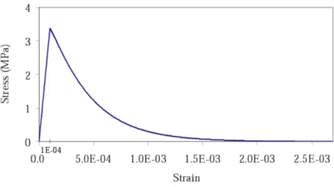
a larger strain than elsewhere. The material parameters of the damage model are provided in Table 1 and Fig. 2
shows the material response in tension. we E
7
.
37
=
E
GPaY
D0=
10
−431
=
weE
GPaA
t=
1
0
=
υ
B
t=
20000
Figure 2: Stress-strain relation for the chosen set of material parameters
In order to exhibit the influence of the internal length and consequently of the size of the fracture process zone
(FPZ), we have used two values of the internal length
l
cin the integral model: lc=0.18m for the small FPZ(SFPZ) and for the large FPZ (LFPZ). The
c
parameter in the gradient enhanced approach wascalibrated such that the integral and gradient models give the same FPZ width, that is, the same width of both the
damage profiles. We obtained for the small FPZ and for the large one. Two finite
element meshes are considered too: a coarse mesh of 31 elements and a fine mesh of 61 elements.
m lc =0.28 2 005 . 0 m c= c=0.012m2
1. Integral and gradient damage responses
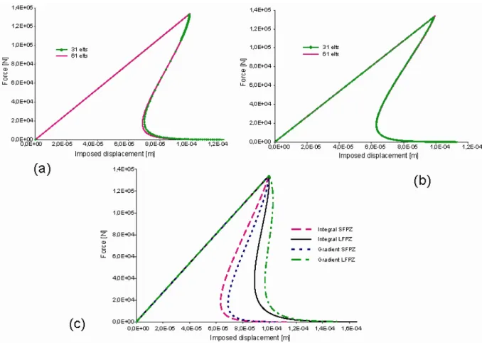
The global response is shown for the gradient model in Fig. 3a and for the non local model in Fig. 3b. These
computations have been performed with the smallest value of the internal length in both non local models and
for the fine and coarse meshes. We can observe that finite element results are not sensitive on the mesh size,
which means that FE convergence with respect to the finite element size has been reached (for both large and
small internal lengths). It is worth noting that due to the shape of the weight function (less sharp), the FE
convergence is reached for a smaller number of finite element in the case of the integral approach. An arc-length
Figure 3: Global response for the integral approach (a), for the gradient approach (b) for two meshes and for the
smallest internal length. The global response (c) for the fine mesh, the two regularization techniques and the two
FPZ sizes.
Fig. 3c illustrates the differences between the gradient and integral approaches. Keeping the same size for the
FPZ according to both models provides a difference between the load deflection curves. Conversely, Jason et al.
(2004) calibrated the gradient model in order to obtain the same load v.s. displacement response as for the
integral model. In this case,
c lc
is approximately 2.55.
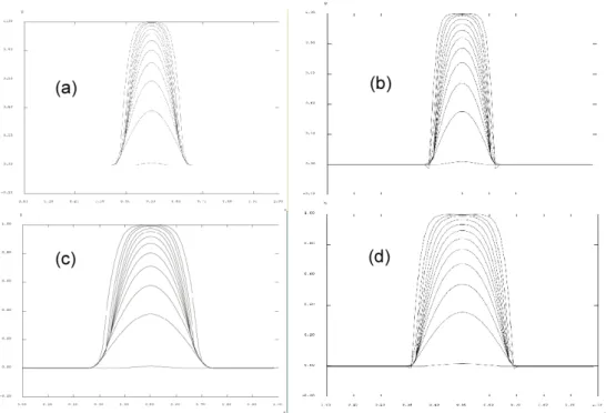
We plot damage and strain profiles in the post-peak regime for several ratios of the load to the peak load in the
post-peak regime. Fig. 4 shows the corresponding evolution of damage profiles. As soon as damage starts to
increase the width of the damaged zone is roughly twice the internal length (of the integral model) and it remains
constant throughout the fracture process. Although the FPZ width has been calibrated to be the same for both
regularization techniques, one can observe that the gradient model presents sharper peaks on the damage profiles
Figure 4: Evolution of damage for the small FPZ with the gradient (a) and the integral (b) approaches, and for
the large FPZ with the gradient (c) and the integral (d) approaches. Thick curves corresponds to damage
profiles almost at complete failure, when the load is 1% of the peak load.
Fig. 5 shows the strain profiles along the bar that correspond to the damage profiles in Fig. 4. There is a
consistent difference between the integral and the gradient approaches on these curves. The width of the strain
profile is smaller according to the gradient approach than that of the integral approach. This is more clearly
illustrated with the largest value of the internal length – comparing Fig. 5c and 5d. The strain profile is sharper
according to the gradient approach, and this provides the difference observed on the load – displacement
responses obtained with the two models. These differences can be regarded also as the consequences of a sharper
equivalent weight function according to the gradient approach compared to the Gaussian function used in the
Figure 5: Strain profiles evolution during loading for the small FPZ with the gradient (a) and the integral (b)
approaches and for the large FPZ with the gradient (c) and the integral (d) approaches.
2. Estimation of crack opening
We are now going to compare the computed regularized effective strain profiles with the profiles derived from
the strong discontinuity analysis, derive the estimate of the crack opening and compute the distance between the
two profiles which is a failure indicator, or equivalently an error indicator on the accuracy of the crack opening
estimate. We consider first a state of damage which is close to complete failure. The ratio of the load to the peak
load is 0.01 and the corresponding damage profiles are those drawn with a thick curve in Fig. 4. Figure 6 shows
this comparison for the smallest internal length. By definition, the profiles coincide in the centre of the bar, the
location with the highest value of damage and effective regularized strain, and the displacement jump
[ ]
U iscomputed from this condition. The profiles deduced from FE computations are wider, but overall, the strong
Figure 6: Regularized effective strain profiles from the strong discontinuity approach (Dirac) and from FE
computations using the integral technique (a) or the gradient technique (b) for the smallest FPZ width.
Figure 7 shows the estimates of the crack opening (Fig. 7a) and the evolution of the error indicator computed
according to Eq. (17) in the course of the loading history. The load level considered in Fig. 6 corresponds to
the black dot in Fig. 7. Once the crack is fully opened the increase of its opening is equal to the displacement
applied at the active end of the bar as no further strain are stored in the material (see Fig. 7a). Therefore the plot
of the displacement jump versus the imposed displacement tends to the bisecting line. The error indicator (see
Fig. 7b) is quite large just after the peak load since the macro-crack is not yet clearly formed. If damage would
have been uniformly distributed along the bar, the error would be even higher. Afterwards, the error indicator
decreases rapidly to reach a limit value of 4% for the integral approach and 2% for the gradient regularization.
These values represent the level of ability of such regularized damage models to simulate discontinuous failure
in terms of kinematic variables. They illustrate also the influence of the weight function. As pointed out in
section 2, the major difference between the gradient and the integral approach is the weight function. With a
sharper weight function, the estimate of the crack opening seems to be improved. Still, a limit value of the error
Figure 7: Crack opening as a function of imposed displacement (a) or maximum strain (c) ; relative error as a
function of imposed displacement (b) or maximum strain (d). Plots are given for the two regularization
techniques with the smallest FPZ width. The black dot corresponds to a load level of 1% of the peak load in the
softening regime.
Fig. 8 shows that the evolution of the crack opening displacement and the quality of the crack opening estimates
are not really dependent on the size of the FPZ. With a small FPZ (small internal length), snap-back on the load
displacement response is more severe and limit values of the error are reached for a smaller applied
displacement. Nevertheless, the results are quite similar. On this figure, the results obtained with the integral
Figure 8: Crack opening as a function of imposed displacement (a) or maximum strain (c); relative error as a
function of imposed displacement (b) or maximum strain (d). Plots are given for the integral damage model and
for the two sizes of FPZ.
V. Conclusions
We have presented in this paper a post processing technique for the evaluation of a crack opening displacement,
or its 1D equivalent, a displacement jump, from failure analyses based on regularized damage models. Instead of
inserting into the kinematics of the problem the strong discontinuity and the inherent constitutive response, the
estimate of the crack opening is based on the comparison of two strain distributions: the regularized effective
strain that derives from a non local (integral or gradient) model and the regularized effective strain that is derived
from a strong discontinuity that is placed at the expected crack location. By definition, these are two regularized
continuous fields that can be approached with standard discretization techniques. If these distributions are close
to each other, it means that the variable that control damage has reached a distribution that is close to that of a
real crack and it is expected that the corresponding distribution of continuous damage is close to that resulting
regularized fields, the amplitude of the displacement jump and an error indicator on these estimate, that defines
also how far from complete failure the distribution of effective strain is, are computed. Close to complete
failure, this post processing technique provides an estimate of the crack opening displacement from a finite
element computation with an error of a few percent. Although the method is illustrated on a 1D example, it can
be extended to 2D analysis too (Legrain et al. (2007)).
The technique applies readily to the integral non local damage model where the regularization is explicit. In the
gradient model, the calculation of the regularised strain distribution from the strong discontinuity displacement
field is required. An alternative averaging technique – same as for the integral model – has been devised in order
to compare effective strain distributions. The comparison between results obtained according to the non local
integral and gradient damage models show that both approaches provide results that are similar. The quality of
the crack opening estimate depends on the weight function that enters in the non local expression. The gradient
approach is equivalent to a non local average with a sharper distribution, lending less weight to neighbouring
points compared to the Gaussian distribution in the classical integral approach. As a consequence, the gradient
approach provides better limit values of the quality for a formed crack than with the integral model.
Note that when damage is fully developed, the profiles of damage start to enlarge slightly according to the two
models. This spurious feature has been already observed by Geers and co-workers (1998) who devised a possible
remedy and restricted the non local averaging process to zones where damage grows. This modification of the
non local damage model is expected to provide a better description of complete failure and should result into an
error indicator on the quality of the crack opening estimate that is improved. This point remains to be
investigated, along the quality of the crack opening estimate performed with existing models in which the
internal length is changing in the course of damage, and of course validation using experimental data.
Acknowledgement: financial support from the Agence Nationale de la Recherche through the non thematic
programme (contract NT05-4_43689) is gratefully acknowledged.
REFERENCES
Choinska M., Khelidj A., Chatzigeorgiou G., Pijaudier-Cabot G. (2007), Effects and interaction of temperature
and stress level related damage on permeability of concrete, Cement and Concrete Research, 37, 79 – 88.
Comi, C., Mariani, S. and Perego, U. (2007). “An extended FE strategy for transition from continuum damage to
Geers, M.G.D., de Borst, R., Brekelmans, W.A.M., Peerlings, R.H.J., (1998). “Strain-based transient-gradient
damage model for failure analyses”, Computer Methods in Applied Mechanics and Engineering, 160, 133-153
Hearn N. and Lok G. (1998), Measurement of Permeability under Uniaxial Compression-A Test Method, ACI
Materials Journal, 95, 691-694.
Hillerborg, A., Modeer, M. and Pertersson, P. E. (1976). “Analysis of crack formation and crack growth in
concrete by means of fracture mechanics and finite elements”. Cement and Concrete Research, 6, 773-782.
Jason, L., Ghavamian, S., Pijaudier-Cabot, G., Huerta, A., (2004) “Benchmarks for the validation of a non local
damage model”, Revue Française de Génie Civil, 8, pp. 303-328.
Jirasek, M., Rosholven, S., Grassl, P. (2004), “Size effect on fracture energy induced by nonlocality”, Int. J.
Num. Anal. Meth. Geomechanics, 28, 653-670.
Larsson, R., Steinman, P. and Runesson, K. (1998), “Finite element embedded localization band for finite strain
plasticity based on a regularized strong discontinuity”, Mech. of Cohe.-Frict. Mat., 4, 171-194.
Legrain G., Dufour F., Huerta A., Pijaudier-Cabot G. (2007), Extraction of crack opening from a non local
damage field, Proceedings of IX International Conference on Computational Plasticity, 1, 462-465, Barcelona,
Spain
Mazars, J. and Pijaudier-Cabot, G. (1989), “Continuum damage theory: application to concrete”, J. Engrg.
Mech., 115, 345-365.
Mazars, J. and Pijaudier-Cabot, G. (1996), “From damage to fracture mechanics and conversely: a combined
approach”, Int. J. of Solids and Struct., 33, 3327-3342.
Oliver, J., Huespe, A. E., Pulido, M. D. G. and Chaves, E. W. V. (2002), “From continuum mechanics to fracture
mechanics: the strong discontinuity approach”. Eng. Frac. Mech., 69, 113-136.
Oliver, J., Huespe, A. E., Pulido, M. D. G. and Blanco, S. (2004), “Computational modelling of cracking of
concrete in strong discontinuity settings”, Comp. & Conc., 1, 1, 61-76.
Peerlings, R. H. J., de Borst, R., Brekelmans, W. A. M., de Vree, J. H. P. (1996), “Gradient enhanced damage for
quasibrittle materials”, Int. J. Num. Meth. Engrg., 39, 3391-3403.
Peerlings, R. H. J., Geers, M.G.D., de Borst, R., Brekelmans, (2001), “A critical comparison of non local and
gradient enhanced softening continua”, Int. J. Solid, Struct., 38, 7723-7746.
Pijaudier-Cabot, G. and Bazant, Z. (1987), “Nonlocal damage theory”, J. of Eng. Mech., 113, 1512-1533.
Planas, J., Elices, M. and Guinea, G. V. (1993), “Cohesive cracks versus nonlocal models: Closing the gap”, Int.
Simo, J. C., Oliver, J. and Armero, F. (1993), “An analysis of strong discontinuities induced by strain softening
in rate-independent inelastic solids”, Comp. Mech., 12, 277-296.
Simone, A., Wells, G. N. and Sluys, L. J. (2003), “From continuous to discontinuous failure in a gradient
enhanced continuum damage model”, Comp. Meth. in Appl. Mech. and Eng., 192(41-42), 4581-4607.
Simone, A., Askes, H., Sluys, L.J.,(2004), “Incorrect initiation and propagation of failure in non-local and
gradient-enhanced media”, Int. J. Solids Struct. 41, 351–363.
Sugiyama T., Bremner T.W., Holm T.A. (1996), Effect of Stress on Gas Permeability in Concrete, ACI
Materials Journal, 93, 443-450.