HAL Id: hal-00995276
https://hal.archives-ouvertes.fr/hal-00995276
Submitted on 23 May 2014
HAL is a multi-disciplinary open access archive for the deposit and dissemination of sci-entific research documents, whether they are pub-lished or not. The documents may come from teaching and research institutions in France or abroad, or from public or private research centers.
L’archive ouverte pluridisciplinaire HAL, est destinée au dépôt et à la diffusion de documents scientifiques de niveau recherche, publiés ou non, émanant des établissements d’enseignement et de recherche français ou étrangers, des laboratoires publics ou privés.
Application of non destructive testing to the detection
of aeronautical defects in composite structure
Victor Munoz, Marianne Perrin, Marie-Laetitia Pastor, Hélène Welemane,
Arthur Cantarel, Moussa Karama
To cite this version:
Victor Munoz, Marianne Perrin, Marie-Laetitia Pastor, Hélène Welemane, Arthur Cantarel, et al.. Application of non destructive testing to the detection of aeronautical defects in composite structure. Nonconventional Technologies Review, 2013. �hal-00995276�
To link to this article :
http://www.revtn.ro/no4-2013.html
This is an author-deposited version published in: http://oatao.univ-toulouse.fr/ Eprints ID: 11217
To cite this version:
Munoz, Victor and Perrin, Marianne and Pastor, Marie-Laetitia and Welemane, Hélène and Cantarel, Arthur and Karama, Moussa Application of non destructive testing to the detection of aeronautical defects in composite structure. (2013) Nonconventional Technologies Review . ISSN 1454-3087
O
pen
A
rchive
T
oulouse
A
rchive
O
uverte (
OATAO
)
OATAO is an open access repository that collects the work of Toulouse researchers and makes it freely available over the web where possible.
Any correspondence concerning this service should be sent to the repository administrator: staff-oatao@listes-diff.inp-toulouse.fr
APPLICATION OF NON DESTRUCTIVE TESTING TO THE DETECTION OF
AERONAUTICAL DEFECTS IN COMPOSITE STRUCTURES
Munoz Victor 1, Perrin Marianne 2, Pastor Marie-Laetitia 2, Welemane Hélène 1, Cantarel Arthur 2 and Karama Moussa 1
1 PRES Université de Toulouse, INP, ENIT-LGP, 47 av. Azereix, BP 1629, 65016 Tarbes Cedex, France 2
PRES Université de Toulouse, UT3, IUT-ICA, 1 rue Lautréamont, BP 1624, 65016 Tarbes Cedex, France victor.munozcuartas@enit.fr, marianne.perrin@iut-tarbes.fr, marie-laetitia.pastor@iut-tarbes.fr, helene.welemane@enit.fr,
arthur.cantarel@iut-tarbes.fr, moussa.karama@enit.fr
ABSTRACT: A study of two Non-destructive Testing methods (NDT) was carried out in specimens with different kinds of simulated defects. Ultrasonics test (US) and Infrared Thermography (IRT) were applied with the aim to evaluate the detectability and the accuracy of each method. These techniques have acquired great importance in the aeronautics industry because they allow to control the aerostructures without intervening in their physical and mechanical integrity. In the second part of the study, a comparison of both techniques was achieved in order to analyse their limits and advantages. It appeared that detectability of defects was much better in a sample with flat-bottomed holes defects in the case of Ultrasonic Test. However it was found that Infrared Thermography is much more limited to the thickness of the specimen than the ultrasonic waves. On the other hand, defects were all revealed with IRT in a sandwich composite including Teflon inserts, which was not the case for US.
KEY WORDS: Non-destructive testing; Ultrasonics; Infrared thermography; Composites; Simulated defects
1 INTRODUCTION
The use of composites in the aerospace industry has increased dramatically since the 1970s. The primary benefits that composite components can offer are the reduction of weight and the simplification of assembly. When they are in service, different types of mechanical and thermal loads are applied to these structures. They generate internal stresses. It is in this way that delamination or disbonding may result in the aerostructure. Defects such as random inclusions or undesirable material have also been found during the manufacture process of composite materials [1]. These flaws may lead to stress concentration with serious consequences. It is therefore important to test the composite structure to ensure their integrity. These defects have to be revealed in order to make the correct maintenance or replacement. The faster the damage or defect is detected, the safer the aerostructure is.
Many techniques have been used in order to detect such defects in the operational configuration. Liquid penetrant inspection [2], magnetic control inspection [2], eddy currents control [2], radiographic testing [5] and shearography [2] are some of the methods used to evaluate the material health, without altering its properties. These kinds of controls are called the Non-Destructive Testing (NDT). The most widespread technique is the ultrasonic testing. It is the only technique certified by the aeronautics industry [3]. Ultrasonic Test (US) uses high
frequency waves to conduct examinations and make measurements. Ultrasonic inspection is used for flaw detection/evaluation, dimensional measurements and material characterization [4]. Some studies have already shown the detectability and the accuracy of a flaw in size, shape and depth for different kinds of composite structures used in the aeronautic industry [1, 5].
A full-field measurement technique based on Infrared Thermography (IRT) is also used in the NDT field. Infrared thermography is a non-destructive, non-intrusive, non-contact mapping of thermal patterns or thermograms, on the surface of objects. IRT is more widely used in recent years for structural investigation [5]. The main difference about IRT with regard to US is that the former does not give the information about the depth of defects. However, detection is faster than US. In fact, the detection of defects with IRT is immediate; whilst that in US, analysis takes about 10 minutes. Some works aimed at comparing different infrared thermography configurations have detailed the accuracy of defects detection [5,6].
The aim of this work is to evaluate two different specimens by ultrasonic test and infrared thermography. Tests on a carbon-epoxy laminated composite and a carbon-epoxy-glass sandwich composite were carried out to check the accuracy and detectability of their simulated defects by using both NDT methods. Specimens have different kinds
of defects and were made in different materials used in the aeronautic industry. Defects have various diameters and locations on the material so that the size limit and deep detection can be determined. The second objective is to compare the data provided by each technique and to find out the advantages of each one to show their possible complementary relative to each other. Finally, a conclusion about the intention to capitalize the information obtained by NDT methods is presented.
2 SPECIMENS AND EXPERIMENTAL SETUP
2.1 Specimens
The specimen used to compare the detectability and accuracy between the IRT and the US is a carbon/epoxy laminated composite with flat bottomed holes defects and variable thickness. It is called specimen A (figure 1). This sample is divided in 2 sections. The first one is 4 mm wide in 50 mm long. The second section is 130 mm long with 8 mm wide. This sample contains 15 holes with diameters ranging from 2 mm to 10 mm. These holes have different depths (from 0.52 mm to 7.5 mm). The aim of these holes is to simulate discontinuity on the specimen that is considered as a continuous medium.
Figure 1. Manufacturing drawing of the specimen A
The second sample, called specimen B, was only tested with infrared thermography because of its material properties. This specimen is a carbon-glass-epoxy skin with foam-core sandwich composite
including Teflon inserts. Its skin is 0.66 mm thick. It has been demonstrated that the foam-core is a sound insulation; thereby the ultrasonic waves cannot penetrate this specimen and be detected by the receiving transducer [5]. This specimen contains 18 defects. These simulated flaws are Teflon inserts ranging from 3 mm to 6 mm. They are located at the skin section. These inserts were placed during the stacking of the tissues so that they simulate as well as possible a delamination within the sample. The manufacturing drawing of this specimen is shown in figure 2.
Figure 2. Manufacturing drawing of the specimen B
2.2 Experimental setup
2.2.1 Ultrasonics
In ultrasonics, the sound energy is introduced and propagates through the material in the shape of
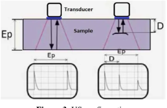
waves. When there is a discontinuity (such as inclusion, delamination or disbonding) in the wave path, part of the energy will be reflected back from the flaw surface. The reflected wave signal is turned into an electrical signal by the transducer and is displayed on a screen. The configuration used on this US testing is called reflection mode (figure 3). One transducer is used to send and receive the wave at the same time.
Figure 3. US configuration
This technique allows to get information about the material elasticity by measuring the wave velocity [7]. The depth, the size and the shape of a detected defect can also be obtained by this technique.
In this study, an Omniscan 32: 128 PR is used with a 5L64-NW1 multi-elements transducer connected to it. The transducer is both ultrasonic source and receiver at the same time. The frequency of it is 5 MHz, which is the common frequency in aeronautics NDT [5]. For specimen A, the wave velocity is 2983 m s-1 with a standard deviation of 5.7 m s-1. This experiment was carried out by contact; therefore it is necessary to use a coating gel between the sample and the transducer. Ultrasonic testing enables two-dimensional mapping, accordingly a coding system is used to detect the position of the transducer. Specimen A was placed in a support to hold it while the experiment was being carried out. Figure 4 shows the ultrasonics device.
Figure 4. Ultrasonic measurement
2.2.2 Infrared Thermography
Infrared thermography (IRT) provides maps and movies of the surface thermal field of specimens; in this way, local changes in surface temperature indicate subsurface defects. Thermal waves are propagated through the material. When they pass through a medium with different thermal conductivity, a thermal gradient is generated in the specimen. Indeed, the two mediums have different thermal conductivities. These differences are captured by an infrared camera enabling the heat emitted by the sample to be converted to temperature. It is measured on the front of the specimen. Thermal two-dimensional mapping is created and heterogeneities can be detected [1,5,6]. This technique allows to get information about the position, the size and the shape of the flaw. So, delamination, disbonding or crack networks can be detected [1].
The heat source is a 1000 W halogen lamp. It is used in two configurations: transmission and reflection mode (figure 5). Specimen A and B were tested in both modes (figure 5a and 5b). The infrared sensor was an IR camera with thermal resolution of 20 mK. A 30 s and 50 Hz movie was recorded in which 15 s corresponds to the heating of the sample and the 15 last seconds to its cooling. These times are long enough to heat the sample and make defects to appear in the thermal mapping. Defects are thermally visible while the heating and cooling of the sample. The treatment of the movie was done with the ALTAIR software. The analysis of the movie is done in relative mode with the purpose to remove the ambient temperature and all environmental noise.
b) Reflection mode
Figure 5. Infrared measurement
Lock-in IRT was also used on both specimens. In lock-in IRT temperature modulation induced at the surface of the inspected component from the outside propagates as a harmonic thermal wave. Lock-in IRT allows a better defect inspection than common IRT and it is less sensitive to environmental conditions [8]. The connection of the lock-in IRT is detailed on figure 6. A signal generator is also needed in addition to the classical IRT.
Figure 6. Lock-in thermography connection
3 RESULTS 3.1 Ultrasonics
As said on section 2, only specimen A was tested with ultrasonics, because foam-core properties in specimen B prevent wave propagate.
Results analyses are made through two parameters: detectability and accuracy. 14 of the 15 holes (93%) were detected by US. The only defect that was not detected is located at 1 mm deep and 2 mm diameter. It is noticed that defects located near the contact surface (less than 1 mm) are hardly distinguished from the signal input peak. Nevertheless defects at 0.52 mm deep were visible in the C-Scan mapping (figure 7). On the other hand, the detected defects were measured on average 1 mm larger or smaller than they really are. Defects located at 7.5 mm deep (3 and 6 mm diameter) were measured 1 mm smaller than their real size, and those located at 5.2 mm deep (2, 3 and 6 mm diameter) were measured at the correct dimension. 10 mm diameter defects were all measured 1 mm larger than their real size. Table 1 shows the measured dimension for each range of defects.
Table 1. Defect measurement on specimen A using US
Depth (mm) 0.52 1 2.8 5.2 7.5 Real diameter (mm) Measured diameter (mm) 10 11 - 11 11 11 6 7 - 6 6 5 3 4 - 4 3 2 2 - Undetected - 2 2
Figure 7 shows the C-Scan mapping for this specimen in which measurements were done.
The size of defects was measured with a visual rule. In this case it is said that there is a defect where the colour of the health part changes and becomes a circular spot with another colour.
Figure 7. C-Scan mapping on specimen A
Other works [5] have obtained similar detectability with a better accuracy for the same specimen. The gap between the real size and the measured size was 0.5 mm. Those measurements were done by using the –6 dB method. It consists in measuring the defect where the backwall echo decreases of 50% [4].
3.2 Infrared thermography
3.2.1 Specimen A
As in US test, two parameters were taken into account to analyse the results: detectability and accuracy. A single picture must be selected from the recorded film. That selection depends on the quality of the image for each defect. In this study, for specimen A, 2 different images in transmission mode (figure 8) were selected to measure 2 ranges of defects located in two different sections of the specimen. These ranges of defects are located at 0.52 mm and 2.8 mm deep respectively and they are in the 4 mm width section and 8 mm width section of the sample. Figure 8 shows that only 6 from the 15 defects, were detected using classical IRT in transmission mode.
Figure 8. IRT mapping of specimen A
Defects at 0.52 mm deep were measured using image 8a and those at 2.8 mm deep using image 8b. In figure 8b it is noticed that heat saturation is generated after a short period of time. The 4 mm width section is rapidly saturated and in the 8 mm width section, no other defect is revealed with the increasing temperature.
The size of the measures defects has the same gap than in US testing. They were measured 1 mm larger than they really are. Table 2 shows the detailed size of the defects.
Table 2. Defect measurement on specimen A using IRT
Depth (mm) 0.52 1 2.8 5.2 7.5 Real diameter (mm) Measured diameter (mm) 10 11 - 11 Undetected Undetected 6 7 - No measurable Undetected Undetected 3 4 - Undetected Undetected Undetected
2 - 2 - Undetected Undetected
6 mm diameter defect at 2.8 mm deep was detected but no measurement could be done because the temperature difference between damaged and healthy parts was not enough to be measured. It is also noticed that the number of detected defects decreases with depth. While the defect is deeper, more difficult is the detection.
In lock-in IRT, the number of detected defects in specimen A increased. Best results were obtained in reflection mode and with 0.1 Hz frequency. However, no measurement of their size was done because of the poor temperature contrast. In addition to classical IRT (with transmission mode), 3 mm diameter defect at 2.8 mm deep and 5.2 mm deep defects (6 and 10 mm diameter) were visible as shown in figure 9.
Figure 9. Lock-in IRT in specimen A
3.2.2 Specimen B
In the case of specimen B, lock-in IRT leads to similar results as classical IRT. All defects were detected and they could be measured in diameter (figure 10).
Figure 10. Lock-in IRT in specimen B
Better results were obtained at 0.1 Hz for both specimens tested in lock-in IRT. It was found that the textured surface of specimen B was confounded with the defects in IRT mapping. Measurements were therefore less accurate than classical IRT in specimen A.
Defects located at the camera side were easily distinguished whereas, defects located on the opposite side of the camera, were difficultly detected. That is way both skins of the sandwich were tested. In addition, the dimension of the measurements was 2 or 3 mm larger than the real size of the defect. Table 3 shows the measured size for each range of defects.
Table 3. Defect measurement on specimen B using lock-in
IRT
Real diameter (mm) Measured diameter (mm)
6 8
3 5
Péronnet et al. [5] tested the same sample and found a gap between real size and measured size ranging from 1.5 mm to 3.5 mm. This stands in accordance with the present study.
Nowadays there is no specific method for measuring the real size of a defect from an IRT mapping. The criterion clearly depends on the operator. In some works, the size of defects has been calculated using a system of grey image measurement [5].
4 ANALYSIS
A comparative analysis was done between both techniques. Table 4 summarizes the limits of detection for each technique regarding different parameters that were also measured while doing the tests.
The C-Scan mapping in US shows that detectability is more affected by the diameter of defects rather than thickness. This detection becomes more difficult when the defect is close to the detecting
surface and to the backwall (less than 1 mm). In this case the defect echo is coincident with the echo of the detection surface.
On the other hand, it is clearly noticed that IRT is very limited to large thicknesses. Defects are not visible beyond 2.8 mm in a carbon-epoxy laminated composite because heat diffusion inside the material does not reach the inspected surface in transmission mode (figure 5a). However, by the use of lock-in
IRT, the thickness reached comes to 5.2 mm in reflexion mode (figure 5b). At any rate, diameter of defects also affects the detectability in IRT. Figure 8b and 9 show that flaws located in the same range of deepness with different diameter are not all detected. The heat diffusivity inside the material does not lead to enough temperature difference in the surface of the sample.
Table 4. Characteristics of US and IRT
Parameter US IRT
Accuracy in size 1 mm (larger) 1 to 2 mm (larger)
Minimal diameter 2 mm from 1 mm deep 2 mm from 0 mm deep
Detection in depth More than 8 mm in laminated composites
2.8 mm for a 6 mm diameter defect in laminated composites
Detectability in the laminated composite
14/15. Non detected a 2 mm defect at 1 mm deep
6/15. Non detected defects beyond 5.2 mm deep and 3 mm diameter
Detectability in foam-core sandwich composites
- 18/18 by analysing both sides of the
sample
Time for getting results About 10 min Instantly
General limitation Detection of defects close to the inspection surface and the backwall
Important specimen thickness In the case of lock-in thermography, low frequencies
are more convenient for detecting the flaws in both specimens. The use of a sinusoidal signal with low frequency (0.1 Hz) allows to optimize the wave spread in the specimen thickness. Other works [6] with the same sample found that the best frequency for detectability of defects is 0.05 Hz.
For the carbon-glass-epoxy skin with foam-core sandwich composite, the use of infrared thermography is quite difficult since the foam is a thermal insulator. It is recommended to control the 2 skins of the sandwich separately and in reflection mode (figure 5b). Otherwise, the heat flux may not arrive to the detection surface.
It was found that detection time in IRT is immediate; however the analysis time is almost the same for both techniques due to the visual methods used to calculate the defects diameter. In US the detection time is longer because the whole surface has to be scanned by the transducer to get the C-Scan mapping.
5 CONCLUSION
The subject of this study was to compare the ultrasonics test and the infrared thermography as NDT techniques. By using 2 different samples, it was shown that both methods have the same accuracy regarding the diameter of the flaws, which is not the case for detectability parameter. 93% of defects in a carbon/epoxy laminated composite were
detected by the US while only 60% of them were detected by the IRT.
In the case of a carbon-glass-epoxy skin with foam-core sandwich composite, all defects were detected by IRT. Results were similar using both, classical IRT and lock-in IRT for this specimen, but the measured size was less accurate than for the laminated composite. The textured surface was confused with the defects. It is also remarkable that no defect was detected by the use of US in this specimen due to absorption of ultrasonics waves by the foam-core.
Based on the results obtained with this study, it is noted that both techniques could be complementary. Firstly, IRT could give the information about the presence of defects and their position; then an US test would give the information about their size, their kind and also their depth.
In future works, mechanical characterization on carbon-epoxy laminated composites will be studied by calculating the elastic constants from the velocity of the ultrasonic waves. Then NDT techniques will be used for monitoring the damage evolution. Static and dynamic tests (tensile, fatigue) will be carried out and at the same time, NDT techniques (Ultrasonics, Infrared Thermography and Acoustic Emissions) will monitor the damage evolution. 6 REFERENCES
1. Garnier C, Pastor ML, Eyma F, Lorrain B. The detection of aeronautical defects in situ on
composite structures using Non Destructive Testing. Composite Structures 93, pp. 1328-1336, 2011.
2. Cherfaoui M. Essais non destructifs. Techniques de l’ingénieur bm6450, 2006.
3. Boro-Djordjevic B. Ultrasonic characterization of advanced composite materials. The 10th International Conference of the Slovenian Society for Non-Destructive Testing, pp. 47-57, Ljubljana, Slovenia, 2009
4. Budnik C. Essais non destructifs – Contrôle par ultrasons. Techniques de l’ingénieur am5407, 2012.
5. Péronnet E. Identification expérimentale du comportement d’un fuselage composite: détection de défauts par mesures de champs. PhD thesis, 2012.
6. Péronnet E, Pastor ML, Huillery R, Dalverny O, Mistou S, Welemane H. Non destructive investigation of defects in composite structures by three infrared thermographic techniques. 15th International Conference on Experimental Mechanics, Porto, Portugal, 2012.
7. Baste S, Hosten B. Evaluation de la matrice d’élasticité des composites orthotropes par propagation ultrasonore en dehors des plans principaux de symétrie. Physique Appliquée 25, pp. 161-168, 1990.
8. Choi M, Kang K, Park J, Kim W, Kim K. Quantitative determination of a subsurface defect of reference specimen by lock-in infrared thermography. NDT&E international 41, pp. 119-124, 2008.