To link to this article: DOI: 10.1016/j.surfcoat.2011.06.011
URL:
http://dx.doi.org/10.1016/j.surfcoat.2011.06.011
This is an author-deposited version published in:
http://oatao.univ-toulouse.fr/
Eprints ID: 5729
To cite this version:
Selezneff, Serge and Boidot, M. and Hugot, J. and Oquab, Djar and
Estournès, Claude and Monceau, Daniel Thermal cycling behavior of
EBPVD TBC systems deposited on doped Pt-rich γ–γ′ bond coatings made
by Spark Plasma Sintering (SPS). (2011) Surface and Coatings
Technology, vol. 206 (n° 7). pp. 1558-1565. ISSN 0257-8972
O
pen
A
rchive
T
oulouse
A
rchive
O
uverte (
OATAO
)
OATAO is an open access repository that collects the work of Toulouse researchers
and makes it freely available over the web where possible.
Any correspondence concerning this service should be sent to the repository
Thermal cycling behavior of EBPVD TBC systems deposited on doped Pt-rich γ–γ′
bond coatings made by Spark Plasma Sintering (SPS)
S. Selezneff
a,⁎
, M. Boidot
a, J. Hugot
b, D. Oquab
a, C. Estournès
c, D. Monceau
a aInstitut Carnot CIRIMAT, ENSIACET, 4, allée Emile Monso, BP 44362, 31030 Toulouse Cedex 4, FrancebSNECMA, Z.I. Nord-rue Maryse Bastié BP 129, 86101 Châtellerault Cedex, France cCNRS, Institut Carnot Cirimat & PNF2/CNRS, F-31062 Toulouse, France
a b s t r a c t
Keywords: Pt rich γ–γ′ coatings SPS
Reactive elements
Cyclic high temperature oxidation
In the last decade, an increasing interest was given to Pt-rich γ–γ′ alloys and coatings as they have shown good oxidation and corrosion properties. In our previous work, Spark Plasma Sintering (SPS) has been proved to be a fast and efficient tool to fabricate coatings on superalloys including entire thermal barrier coating systems (TBC). In the present study, this technique was used to fabricate doped Pt-rich γ–γ′ bond coatings on AM1® superalloy substrate. The doping elements were reactive elements such as Hf, Y or Zr, Si and metallic additions of Ag. These samples were then coated by electron beam physical vapour deposition (EBPVD) with an yttria partially stabilized zirconia (YPSZ) thermal barrier coating. Such TBC systems with SPS Pt rich γ–γ′ bond coatings were compared to conventional TBC system composed of a β-(Ni,Pt)Al bond coating. Thermal cycling tests were performed during 1000-1 h cycles at 1100 °C under laboratory air. Spalling areas were monitored during this oxidation test. Most of the Pt rich γ–γ′ samples exhibited a better adherence of the ceramic layer than the β-samples. After the whole cyclic oxidation test, cross sections were prepared to characterize the thickness and the composition of the oxide scales by using scanning-electron microscopy. In particular, the influence of the doping elements on the oxide scale formation, the metal/oxide roughness, the TBC adherence and the remaining Al and Pt under the oxide scale were monitored. It was shown that RE-doping did not improve the oxidation kinetics of the studied Pt rich γ–γ′ bond coatings, nevertheless most of the compositions were superior to “classic” β-(Ni,Pt)Al bond coatings in terms of ceramic top coat adherence, due to lower rumpling kinetics and better oxide scale adherence of the γ–γ′-based systems.
1. Introduction
The efficiency of gas turbines is directly related to their temper-ature of use. Thus, a major issue is to develop systems withstanding increasingly high temperature. To protect turbines blades from exces-sive oxidation and to lower the temperature at the blade surface, a multilayer coating system has been developed in the past, i.e. the Thermal Barrier Coating (TBC). The current state-of-the-art TBC is deposited on a single crystal Ni-based superalloy as substrate. It is composed of an outer layer of YPSZ coated by EBPVD on a bond coating presenting the β-(Ni,Pt)Al phase[1]. The fabrication of TBC is expensive and demands numerous process steps. That is why in the recent years several research groups worked on the development of new generations of bond coatings[2,3], and bulk alloys [4,5], presenting γ-Ni and γ′-Ni3Al phases. Assets of these γ–γ′ coatings are
the absence of Topologically Closed Packed (TCP) phases in the inter-diffusion zone between the coating and the substrate, no detrimental
phase transformation as the coating has already the same crystallo-graphic structure as the substrate, and lower cost as they can be obtained directly from a diffusion treatment of a Pt layer[6,7].
The drawback of γ–γ′ coatings is a relatively low Al content when compared to β-(Ni,Pt)Al. This low Al reservoir can be limiting to ensure exclusive alumina growth for very long service durations. Two main ideas were developed to bypass this weak point. The first one was to add Pt to the coating to permit an uphill diffusion of the Al from the substrate to the subsurface[4,8,9]. To ensure a replenish-ment of Al at the coating subsurface, it was shown that a Pt content greater than15 at.% was required[4,10]. Moreover, Pt has a beneficial effect during oxidation by limiting the segregation of impurities[11]. A second idea was to add reactive elements to lower the oxidation rate and avoid segregation of impurities, such as C[12]and S[13], at the metal/oxide interface. Nevertheless the RE content needs to be carefully adjusted as a too high amount can lead to overdoping and actually reduce the life span[14,15]. By combining these two ideas, Pt-rich γ–γ′ doped with reactive elements were developed and have shown excellent oxidation behavior. Gleeson et al.[16]found that Pt rises the solubility of RE in the coating. From a screening of several bulk materials with different Pt and Al contents these authors have
⁎ Corresponding author. Tel.: +33 534323448; fax: +33 534323498. E-mail address:[email protected](S. Selezneff).
shown that high Pt content γ–γ′ are exclusive alumina formers during 500-1 h thermal cycles at 1150 °C under air and that the best composition is Ni-20Al-20Pt-1Hf (at.%)[16]. High Temperature cyclic oxidation tests were also conducted at 1050 °C, 1100 °C and 1150 °C on Pt rich γ–γ′ coatings and have shown excellent results[17].
Interdiffusion occurs between the substrate and the coating during oxidation. This phenomenon is observed on β-(Ni,Pt)Al [18] but also on overlay coatings. From the oxidation tests conducted on γ–γ′ coatings, it appears that they are particularly sensitive to this inter-diffusion [17,19]. That is why substrate composition, in alloying elements and in impurities, became a major concern as it impacts directly the adherence of the TGO during oxidation. For example, sulphur segregation can lead to premature delamination [20–22]
because it tends to segregate at the bond coating/alumina scale inter-face[23,24]and lower the strength of this interface[25]. To avoid the effect of sulphur segregation, superalloys with low sulphur have to be used and coating fabrication process must not add sulphur. Remaining S needs to be mitigated with reactive elements additions. In this study, Pt-rich γ–γ′ coatings with accurate compositions were fabricated by Spark Plasma Sintering. The SPS process is mainly used for its efficiency to sinter powders rapidly with limited change of their initial microstructures[26]. But it is also a powerful tool to fabricate coatings[27–29]. Several studies have reported the fabri-cation of high temperature oxidation protective coatings[30,31]and one step synthesis of the TBC system [32–34]. But, to the best of authors' knowledge, no TBC systems have been developed by depos-iting EBPVD top coat on SPS bond coatings. The objective of such processing would be to easily fabricate several compositions of bond-coatings and to coat them with standard EBPVD-ceramic top coat, in order to compare their oxidation resistance with standard systems.
In this study, bond coatings have been fabricated by SPS on first generation AM1® single crystal superalloy substrate. These coatings were doped with reactive elements such as Zr, Hf and Y, alone or combined. Ag was added to evaluate its capability to favour the development of an alumina scale as it is observed on γ-TiAl[35,36]
and also as it could increase the Al content in the γ′ phase[37]and then the Al reservoir in the coating. Then, an YPSZ top coat was applied by EBPVD industrial route. Thermal cycling at 1100 °C was conducted on these samples to compare them to state of the art TBC with β-(Ni,Pt)Al bond coating. Spalling was monitored and cross sections were prepared to link the observed behavior with the micro-structure of the coatings, their roughness, their chemical composition, and the TGO composition and growth rate.
2. Materials and methods 2.1. Fabrication
This study compares two types of diffusion bond coatings made on the same substrate, the first generation Ni-base single crystal superalloy AM1®[38]with a low sulphur content (b0.4 ppm), but with large amounts of Ti and Ta elements (Table 1) which can be detrimental from a high temperature oxidation point of view[39]. The same thermal barrier, i.e. an YPSZ (6–8 wt.% Y2O3) fabricated by
EBPVD, was applied to all samples.
Substrates were 24 mm diameter Ni-based discs cut from the same cast rod of AM1®. One of the discs was used to measure the concen-tration of trace elements by Glow Discharge Mass Spestroscopy (GDMS) analysis. This analysis is reported inTable 2and shows low
levels of C, N, O and S. The Hf content of 530 ppm (wt) can improve the oxidation behavior compared to a standard AM1®.
The first kind of coating deposited on these AM1® substrates is a Pt-modified aluminide bond coating, presenting the β-(Ni,Pt)Al phase. The fabrication of these coatings required mainly two steps: a Pt deposition of approximately 7 μm on the substrate through an electrolytic process and an Al enrichment by a vapour phase aluminization (APVS). This AM1/β-(Ni,Pt)Al/EBPVD YPSZ has been widely studied[24,40,41]. Two β-(Ni,Pt)Al bond coatings were pre-pared for this study, they are referenced B-1and B-2.
The second kind of coating is a Pt-rich aluminide presenting the γ and γ′ phases. These coatings were fabricated by Spark Plasma Sintering using a SPS Dr Sinter 2080, Syntex Inc., Japan. Standard 12/2 on/off 3.3 ms pulse pattern was used (i.e. 12 pulses of 3.3 ms followed by 2 rest intervals). Punches and die were made of graphite.
Thin layers of RE (RE = Zr, Y or Hf) and Si, were added by radio-frequency-sputtering (PVD-RF) at ICMCB (Bordeaux, France) using conditions which insure unoxidized deposits on the substrates before SPS treatment. The metallic additions of Ag were made by PVD in our laboratory. The thickness of RE to be deposited was calculated by assuming that RE coated by PVD-RF would be non-oxidised and fully crystallised after PVD and homogenously dispersed in the coating after SPS. Once the doping elements are coated on the substrate, it is kept under an argon atmosphere until the SPS step to prevent the RE from oxidation. In the SPS die, stacks of platinum (purity: 99.95%) and aluminium (purity: 99%) sheets (thickness of 2 or 10 μm) from Goodfellow corp. were loaded onto the substrate. To prevent the sample from carburization during the SPS, hexagonal-BN was sprayed on the carbon paper (PapyexTM) in contact with the sample surface. Details on the SPS route can be found elsewhere[32]. This process has allowed us to obtain various doped bond coatings on AM1 substrates. After SPS, samples were polished with abrasive paper of grade 4000 followed by ultrasonic cleaning in order to take off the residual BN from the samples surfaces. Then a post-SPS annealing at 1100 °C under a dynamic vacuum of 5 · 10−3mbar of Ar (purity 99.9990%)
was made to obtain a Pt rich γ–γ′ bond coating with the desired composition (~Ni–20Al–25Pt in at.%). The targeted compositions and annealing time of the fabricated samples are reported inTable 3.
Table 1
AM1® composition (wt.%)[38].
Element Cr Co Mo W Al Ti Ta Ni
wt.% 7.8 6.5 2 5.7 5.2 1.1 7.9 Bal.
Table 2
Trace elements in AM1® superalloy determined by GDMS analysis (ppm wt).
Element C N O Si S Zr Hf
ppm wt ~ 9 ~ 0.6 ~ 1 63 b 0.4 6.0 530
Table 3
Desired RE compositions and thickness of metallic sheets and RE deposited in γ–γ′ bond coatings. Sample Pt Al Zr Hf Y Si Ag Annealing post SPS h at 1100 °C ID μm μm at.% (nm) at.% (nm) at.% (nm) at.% (nm) at.% (nm) A-1 10 4 0.04 0.04 26 (30) (40) A-2 10 2 0.13 0.15 0.22 0.83 10 (90) (150) (50) (220) A-3 2 0 0.14 2.85 10 (50) (320) A-4 6 0 0.04 10 (20) A-5 10 4 004 0.04 26 (30) (40) A-6 10 4 0.11 26 (80) A-7 4 0 0.11 0.07 1.62 10 (50) (45) (275) A-8 2 0 0.15 10 (50)
Then, these samples were grit blasted with Al2O3particles and
coated by EBPVD with a ceramic top coat of YPSZ at the Ceramic Coating Center of Châtellerault (France) using the industrial process and parameters. The roughness of the bond coatings surfaces' was measured by a stylus profilometer after grit blasting. The thickness of the ceramic thermal barrier deposited was around 150 μm.
2.2. Cyclic oxidation
These coated samples have been thermally cycled at 1100 °C under laboratory air. A cycle is composed of a fast heating up to 1100 °C (less than 10 min) by moving samples into the hot furnace, a hot dwell of 1 h (including heating) and an air forced cooling for 15 min to ambient air. All samples were tested during 1000 cycles before being characterized.
2.3. Characterization
In order to monitor the adherence of the TBC during thermal cycling, pictures of the samples were made after different number of cycles. Image analyses permitted to evaluate the fraction of unspalled area.
After 1000 cycles, cross sections were prepared and characterized by scanning-electron microscopy (SEM) and energy-dispersive spec-troscopy (EDS). The roughness of the bond coating/TGO interface was evaluated from the SEM pictures. The chemical compositions of the TGO and of the bond coating underneath the TGO were also determined using the SEM-EDX.
2.4. Roughness calculation
As described in the literature[42], profiles of the bond coating/ ceramic top coat were obtained by putting together series of SEM contiguous images of cross sections over a distance of at least 1500 μm. Only unspalled areas were studied. Then, bond coating/TGO interface coordinates y(x) were recorded at 5 μm intervals along the x-axis and the surface roughness was evaluated by the calculation of the arithmetic average (Ra):
Ra =1 L ∫ L 0 y0 ∂x ð1Þ
where L is the profile length and y′ the depth measured by zeroing the mean height.
3. Results and discussion 3.1. Pollution during the SPS process
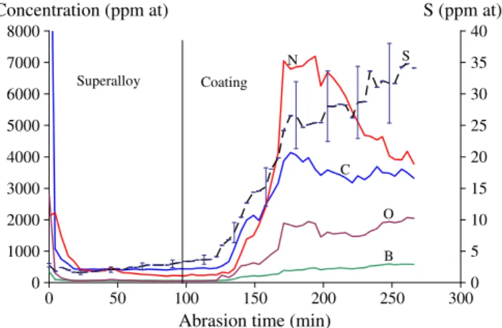
It has been shown already that SPS induces carburization of the samples [30,31]. Present authors have shown that combining the use of a hex-BN sprayed onto the surface of the graphitic paper before the SPS step with a Pt foil at least of 6 μm thick put onto the sub-strate prevent this pollution[32]. However, in order to evaluate the maximum pollution that can be induced by SPS, a bond coating was fabricated on a AM1® substrate with 2 μm thick Pt sheet and analysed by GDMS. After SPS, the sample was mechanically polished from the back side to obtain a 70 μm sample with around 50 μm of super-alloy substrate and the entire bond coating remaining. A back side analysis allows a better determination next to the composition of the metal/oxide interface[24]. Back side GDMS analysis of this sample was conducted and the B, O, C, N and S concentration profiles are reported inFig. 1.
The maximum amount of S is about 35 ppm (at) near the surface of the coating. This value appears high, but the pertinent parameter to be considered is the sulfur overall quantity[43]. It can be also noted that this S pollution is low enough when compared to other processes
used to fabricate aluminide coatings. Nevertheless, there is a lack of published data on this matter. N, C and O levels are of several thousands of ppm but no evidence of the presence of these elements in internal nitrides, carbides or oxides, has been noticed in the SPS fabricated coatings. Some B was also found in the coating by the GDMS analysis but no boron-rich compounds were detected in cross sections observations. In the literature, it can be noted that B can have a positive effect as it has been added to polycrystalline superalloys and to γ′-Ni3Al to increase their ductility[44].
3.2. Adherence of the EBPVD thermal barrier
After SPS and annealing, samples present a quite uniform green surface coming from the transient oxides formed during the early stage of oxidation. On some samples (A-3, A-8) there are still hex-BN residuals remaining. All these oxides and residuals were removed by grit blasting before EBPVD.
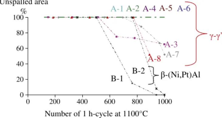
The micrographs taken at the end of thermal cycling are gathered inTable 4. After this cyclic oxidation test, it appears that the ceramic top coat has a better adherence on γ–γ′ bond coatings made by SPS than on β-(Ni,Pt)Al bond coatings. Neither of the β-(Ni,Pt)Al have survived 1000 cycles without spalling whereas five of the eight sam-ples with γ–γ′ coatings have undergone 1000 cycles with no spalling. There is no more contact between the thermal barrier and the bond coating for the sample B-2. It can be noted here that a life higher than 1000 cycles of 1 h at 1100 °C is a good result for a system based on the first generation AM1 superalloy. Evolution of the unspalled area during the cyclic oxidation test is reported inFig. 2for all the samples. Among the eight γ–γ′ samples, the three which partially spalled after 1000 cycles (A-3, A-7 and A-8) are the samples with the lowest amount of Pt (2 or 4 μm) and no Al addition. From the cross sections observations it appears that, for all the samples, the spalling occurs at the bond coating/TGO interface.
The spalling can be explained from two ideas. Firstly, thermal cycling induces stress in the TGO due, mainly, to the coefficients of thermal expansion (CTE) mismatch between the different layers of the TBC system. This stress causes surface undulations increasing with time. This phenomenon is known as rumpling[45–47]. Surface defor-mation and defects concentrate the stresses due to thermal cycling and finally lead to the delamination of the TBC system when the tenacity of interfaces is not sufficient. Secondly, the thickness of the TGO is of crucial importance, as it strongly influences the level of elastic strain energy. Thus the growth rate of the TGO is of utmost importance on the life span of the TBC system. The chemical com-position in the γ phase under the TGO determines the nature of the oxides in the TGO. After[48], β-(Ni,Pt)Al coated CMSX-4 experience the first formation of NiO during cycling oxidation at 1050 °C when
0 1000 2000 3000 4000 5000 6000 7000 8000 0 50 100 150 200 250 300 0 5 10 15 20 25 30 35 40
Abrasion time (min)
S
C N
B O
Concentration (ppm at)
S (ppm at)
Coating Superalloy
Fig. 1. Back side analysis by GDMS of a coating fabricated from a 2 μm thick Pt sheet on AM1.
the Al content in the coating below the TGO reaches 7 at.%. Even if this system is different from ours, they both present the γ phase with similar Pt and Cr contents under the TGO at this stage of oxidation. So 7 at.% seems to be a critical aluminium content in γ phase to form alumina.
To decouple these different effects, several characterizations were made in the following. The microstructure of the bond coating and the TGO were observed on spalled and unspalled areas. Then the rough-ness of the bond coating/TGO interface was calculated to evaluate the importance of rumpling. To estimate the life span of the samples, chemical compositions of the bond coatings subsurface were mea-sured. Finally, the growth rates were calculated, looking for a possible RE effect.
3.3. Microstructure
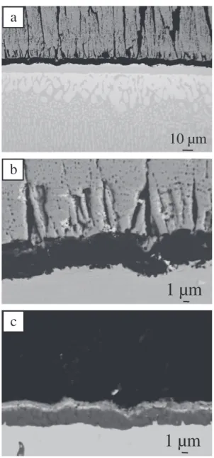
Cross section SEM-BSE micrographs of the sample A-3 are presented inFig. 3.Fig. 3a shows a typical microstructure of a γ–γ′ coating after 1000 cycles. The upper part of the coating is composed of γ-phase. An intermediate layer with predominantly γ′ is observed and finally the γ–γ′ structure of the substrate modified by the Pt diffusion is found.Fig. 3b presents an enlargement of the TGO of an unspalled area. This TGO is exclusively composed of alumina and is around 5 μm thick. Oxide of the reactive element Hf can be found in this scale, appearing as bright spots in BSE mode.Fig. 3c is a SEM image in BSE mode of the TGO growing on sample A-3 after spalling of the initial oxide with the ceramic top coat. An upper bright layer of Ni and Al rich oxides and Ta, Ti rich oxides are observed. The microstructure of this oxide layer is similar to the one observed on TGO grown on AM1® superalloy without any coating[49]. Then it can be concluded that for this part of the sample the coating is no more protective as the oxidation behavior is the same as the bare substrate. It also illustrates the detrimental effect of the high level of Ti and Ta in AM1 superalloy on the high temperature oxidation.
3.4. Roughness
The roughness of all the samples has been measured by stylus profilometer after the grit blasting and before the EBPVD run. The values of the arithmetic average (Ra) are very similar, around 0.45 μm, and are plotted inFig. 4(0 cycle).
The evolution of the roughness parameter Ra of β-(Ni,Pt)Al coating during thermal cycling at 1100 °C was calculated using the routine described in part 2, from cross sections of samples used in a previous study[50]which were fabricated identically to the EBPVD YPSZ/β-(Ni, Pt)Al/AM1 systems of the present study. As no sample with a β-(Ni,Pt) Al bond coating have sustained 1000 cycles without integral spalling, the roughness at 1000 cycles has been measured on B-2, which sur-vived around 800 cycles before spalling. The Ra found for this sample is equal to 6,6 μm. Comparison of the roughness evaluation should be
Table 4 Micrographs of all the samples after the cyclic oxidation test. A-1 A-2 A-3 A-4 A-5 A-6 A-7 A-8 B-1 B-2 After 1000 ∗ 1 h cycles at 1100 °C 0 20 40 60 80 100 0 200 400 600 800 1000
B-2
B-1
A-3
A-8
A-6
A-5
Number of 1 h-cycle at 1100°C
Unspalled area
%
- ’
-(Ni,Pt)Al
A-7
A-1
A-2
A-4
made on the basis of an extrapolation of the values measured on unspalled samples since the roughness rises disproportionately as soon as the TBC has delaminated.
All the samples with Pt rich γ–γ′ bond coatings did show a lower Ra after 1000 cycles. The kinetics of the surface undulations growth are slower for the γ–γ′ coatings because they avoid the martensitic transformation of the β phase, (β-B2➔β-L10-(Ni,Pt)Al) which is
known to be a factor of the rumpling of the β-(NiPt)Al coatings. Moreover, the γ–γ′ sample A-2, with the larger Ra (2.0 μm), is highly doped and presents a lot of pegs containing reactive elements. These pegs, localized at the subsurface of the bond coating, as seen inFig. 5
interfere with the measurement of the TGO/bond coating interface leading to an overestimation of the Ra.
3.5. Life span
In order to estimate the remaining life span of the coatings, the composition underneath the TGO was measured by EDS. Special attention was paid to Pt and Al compositions which permit to evaluate if a coating is still able to form an alumina scale. The graph inFig. 6
puts together the Al and Pt compositions of all the samples after 1000 cycles of 1 h at 1100 °C.
It can be seen inFig. 6that the three γ–γ′ samples which have undergone spalling (A-3, A-7 and A-8) are on the lower left corner. With Al content about 5 at.%, they are under the experimentally determined minimum concentration of Al to form exclusive alumina (~7 at.%)[48]. Therefore, oxides such as NiAl2O4and/or NiO are likely
to form and their high growth kinetics can be the reason of the observed spalling. The last sample with no Al added (A-4) contains 7% of Al and 4% at of Pt. These amounts are enough to form alumina but this sample is near its end of life. This was confirmed during the cross section preparation as this sample has undergone a partial desktop spalling (DTS [51]). The other samples exhibit higher Al and Pt contents, especially the two samples A-2 and A-6 which still have a higher Al content than the superalloy after 1000-1 h cycles.
20 µm
Fig. 5. Sample A-2 cross section, SEM-BSE image (arrows indicate RE some oxide pegs).
0 2 4 6 8 10 12 14 16 0 2 4 6 8
Al (% at)
A-6
A-3
A-8
A-7
A-4
A-1
A-5
A-2
SPALLING
DTS
[Al] in AM1 ®
ADHERENT
Pt (% at)
Fig. 6. Subsurface Al and Pt compositions after 1000 cycles. 0 0.5 1 1.5 2 2.5 3 A-2
Ra (µm)
A-3 A-7 A-8 A-1 A-6 A-5 A-4-(Ni,Pt)Al
spalling
Number of 1h-cycle at 1100°C
0 200 400 600 800 1000Fig. 4. Roughness evolution during thermal cycling.
10 µm
1 µm
1 µm
b
a
c
Fig. 3. SEM-BSE micrographs of A-3 a) view of the TBC system b) TGO of an unspalled area c) TGO of a spalled area.
This means that Pt content still permits an uphill diffusion of Al from the substrate.
From these results, two main conclusions can be drawn. Firstly, the addition of Al to the coating is essential even if a 2 μm sheet of Al may be considered as negligible when compared to the Al content in the 2 mm-thick superalloy. Secondly the bond coatings fabricated just by the interdiffusion of a thin (2 to 6 μm) Pt sheet (A-3, A-4, A-7 and A-8) with the superalloy and the addition of some reactive elements have a life span of about 1000 cycles on a AM1® substrate, which is better than with a β-(Ni,Pt)Al bond coating.
To decouple the effect of the RE and Ag compared to the metallic additions of Pt and Al, the Al content after 1000-1 h cycles at 1100 °C
is plotted as a function of the thickness of the Al additional layer in
Fig. 7.
Fig. 7shows that samples A-2 and A-6 have a higher Al content than A-1 and A-5 despite a lower or equal initial Al addition. This can be seen as evidence of an effect of doping with reactive elements as A-2 and A-6 have high levels of RE compared to A-1 and A-5. Indeed, if reactive elements lower the growth rate of the alumina scale, a higher Al content can be expected in the bond coating below the oxide scale. To validate the potential benefit of the reactive elements, the growth rates were calculated from the alumina layer thickness by assuming a diffusional control of the oxidation process, that is to say simple parabolic kinetics. In that case, the parabolic constant kpis
given by Eq.2:
kp=
3⋅eAl2O3⋅MO⋅ρAl2O3 MAl2O3
2
t ð2Þ
With ρAl203, and eAl203respectively the density and the thickness
of the alumina scale. MAl203is the molar mass of alumina, Mo is the
oxygen molar mass and t is the time of oxidation. This calculation overestimates the value of the parabolic rate constant as it doesn't take into account the transient stage of oxidation. The kpof all the
samples, calculated from their oxide scale thickness after 1000 h, are reported inFig. 8, together with stationary state parabolic constants from the literature. Growth kinetics of alumina scales on NiAl single crystals are plotted from Brumm and Grabke[52]and the chromia area is from Hindam and Whittle[53]. Furthermore the kpof a YSPZ/
β-(NiPt)Al/AM1 has been calculated after 300-1 h cycles at 1100 °C under air and is included inFig. 8 as a black circle. FromFig. 8, it
1.E-07 1.E-06 1.E-05 7.0 7.2 7.4 7.6 7.8 8.0
10
4/T (K
-1)
θ-Al2O3 α-Al2O3 Al2O3 -zoneA-2
A-3
A-7
A-8
A-1
A-6
A-5
A-6
A-2
log k
p(mg
2.cm
-4.s
-1)
A-8
A-4
1 µm
1 µm
1 µm
Cr2O3 -zoneFig. 8. Arrhenius plot of the parabolic rate constants of oxidation of γ–γ′ (◊) and β-(Ni,Pt)Al (○) coated AM1® .reported with data from literature[52,53](see text). 0 2 4 6 8 10 12 14 16 0 1 2 3 4 5 Al sheet thickness (µm) No Al addition A-6 A-3 A-8 A-7 A-4 A-1 A-5 A-2 Al (%at)
Fig. 7. Al content after thermal cycling as a function of the thickness of the additional layer of Al.
appears that all the samples are in the lower part of the alumina-zone. Indeed, TGO details of various samples reported inFig. 8shows that TGO are, in the unspalled areas, mostly alumina, with possibly oxides of reactive elements and transient oxides, as it appears on sample A-2 and A-8. After 300-1 h cycles at 1100 °C, the β-(NiAl)Pt has the same kpas A-5, the γ–γ′ sample with the higher kp. It means that γ–γ′ bond
coatings fabricated by SPS are equivalent or better than conventional β-(NiAl)Pt with respect to the growth rate of the TGO. From a mechanical point of view, the range of the TGO thickness for all the samples is narrow meaning that the oxide thickness cannot be the only reason for spalling. Moreover on similar systems decohesion of TBC has been observed for TGO 10 μm thick[54]whereas the thickest oxide of our study measures 6.6 μm. Thus, for the samples with only Pt, the spalling of the ceramic top coat must come from a local breakaway as on the unspalled area, a thin alumina scale is observed. Breakaway will appear in Al depleted zones as coatings A-3, A-7 and A-8 have a low level of Al reservoir. Surprisingly, the coatings presenting no spalling after 1000 cycles have the highest kp. This
can be rationalized by the fact that they did not suffered from local breakaway because their initial Al and Pt contents (2 or 4 μm addition of Al and 10 μm of Pt) were higher than samples which have ex-perienced spalling (no Al addition and 2–4 μm of Pt).
The whole results for all the samples are summarized inTable 5. Among the 4 resistant samples (A-1, A-2, A-5, A-6) as seen inFig. 2, samples A-2 and A-6 have the best behaviors as shown inFigs. 6 and 7. This could be related to the fact that A-6 has the highest Zr content and A-2 the highest Hf + Y content. These RE additions do not lead to lower apparent rumpling kinetics (Fig. 4), for A-2 because of the presence of RE pegs. These RE additions did not lead to lower oxidation kinetics (Fig. 8) probably because of the way kpis calculated
includes the initial oxidation kinetics which may be higher with higher content of RE. It is possible that after faster initial oxidation kinetics, these samples experience slower oxidation kinetics which would be compatible to the higher final Al concentration under the TGO reported inFig. 6. These RE compositions may also improve the TGO adhesion on the bond coating by forming pegs for example[23]
as it can be seen inFig. 5.
The observation that the parabolic constants are higher than what is measured for alumina growth on pure NiAl can be also related to the relative low RE doping which was tested in this study. Indeed, Ford and al.[55]have shown in a study on Pt-rich γ–γ′ alloys, that a content of Hf higher than 0.25 at.% and lower than 0.8 at.% (optimum at 0.5 at.%) was necessary to obtain the slowest oxidation kinetics. Nevertheless, their study was done on massive samples, at 1150 °C and with more Pt (30 at.%) which allows a higher solubility of Hf
[16]. Concerning the additions of Si and Ag, no clear conclusions can be drawn. The original idea was to add Ag in order to increase the Al content in the coating, following ref [37]. Nevertheless, EDX measurements in the present coatings have demonstrated that Ag was not soluble in γ and γ′ phases and did not increase Al solubility in γ′. Moreover the addition of about 1.6 at.% Ag to sample A-3 or 2.9 at.% Si to A-7 did not compensate the lack of Al for these samples. Despite this last result, it should be noticed that the sample A-2 containing 0.2 at.% Si and 0.8 at.% Ag had an excellent behaviour despite its limited addition of Al (2 μm). More work is then needed to understand the effect of Ag and Si additions.
4. Conclusion
In conclusion, this study reports the ability of SPS to fabricate bond coatings on Ni-based superalloy for being used in a TBC system with an industrial standard YPSZ top coat coated by EBPVD. Even if the pollution analysis by GDMS technique shows quite high maximum contents in C, O and N, the good performances of these coatings under a cycling oxidation test of 1000×1h at 1100 °C under air reveal a good quality of the fabricated coatings. Indeed, the adherence of the ceramic top coat, highly sensitive to impurities segregation, is better for the γ–γ′ coatings made by SPS than for the conventional β-(Ni,Pt) Al made by the industrial vapour phase aluminization. This better adherence can be explained from a mechanical point of view as the Pt rich γ–γ′ coatings have a lower roughness after cyling. Moreover these samples are excellent alumina formers for up to 1000 cycles at 1100 °C but at that point some of the coatings present an Al content lower than the superalloy they protect. The life span of such coatings, on the superalloy AM1 ®, may not exceed largely 1000 cycles. However two samples fabricated from 10 μm of Pt and 2 or 4 μm of Al showed a high level of Al after 1000 h. Excellent behavior of sample A-2 can be related to Pt and Al addition, but also to a combination of RE including Hf, Y and possibly to a positive effect of Ag and Si. These coatings could be possibly improved by a higher level of RE doping in order to reduce their oxidation kinetics.
Acknowledgements
Part of this work was performed thanks to the financial support of DGA and SNECMA. AM1 alloy was furnished by Snecma-SAFRAN company. RF-sputtering was done at ICMCB, Bordeaux, France. EBPVD deposits have been done at Ceramic Coating Center, Châtellerault, France.
References
[1] A. Feuerstein, J. Knapp, T. Taylor, A. Ashary, A. Bolcavage, N. Hitchman, J. Therm. Spray Technol. 17 (2008) 199.
[2] K. Bouhanek, O.A. Adesanya, F.H. Stott, P. Skeldon, D.G. Lees, G.C. Wood, Mater. Sci. Forum 639 (2001) 369.
[3] Y. Zhang, B.A. Pint, J.A. Haynes, I.G. Wright, Surf. Coat. Technol. 200 (2005) 1259. [4] B. Gleeson, W. Wang, S. Hayashi, D. Sordelet, Mater. Sci. Forum 461–464 (2004) 213. [5] N. Mu, T. Izumi, L. Zhang, B. Gleeson, Mater. Sci. Forum 595–598 (2008) 239. [6] A. Nagaraj, United States US005427866A (1995).
[7] D.S. Rickerby, United states US005667663A (1997).
[8] B. Sundman, S. Ford, X.G. Lu, T. Narita, D. Monceau, J. Phase Equilib. Diffus. 30 (2009) 602.
[9] M. Abikchi, A. Vande Put, D. Monceau, unpublished results, (2010).
[10] S. Hayashi, W. Wang, D.J. Sordelet, B. Gleeson, Metall. Mater. Trans. A 36A (2005) 1769.
[11] X. Zhao, P. Xiao, Thin Solid Films 517 (2008) 828. [12] B.A. Pint, J.H. Schneibel, Scripta Materialia 52 (2005) 1199. [13] P.Y. Hou, T. Izumi, B. Gleeson, Oxid. Met. 72 (2009) 109. [14] J.K. Tien, F.S. Pettit, Metall. Trans. 3 (1972) 1587.
[15] B.A. Pint, A.J. Garratt-Reed, L.W. Hobbs, 2nd International Conference on the Microscopy of Oxidation, 1993, p. 463.
[16] T. Izumi, B. Gleeson, Mater. Sci. Forum 522–523 (2006) 221.
[17] J.A. Haynes, B.A. Pint, Y. Zhang, I.G. Wright, Surf Coat. Technol. 202 (2007) 730. [18] R.T. Wu, K. Kawagishi, H. Harada, R.C. Reed, Acta Mater. 56 (2008) 3622. [19] Y. Zhang, J.P. Stacy, B.A. Pint, J.A. Haynes, B.T. Hazel, B.A. Nagaraj, Surf. Coat.
Technol. 203 (2008) 417.
[20] J.L. Smialek, TMS annual meeting: Corrosion and Particle Erosion at High-temperature, 1989, p. 425.
[21] P.Y. Hou, J. Stringer, Oxid. Met. 38 (1992) 323.
[22] W.Y. Lee, Y. Zhang, I.G. Wright, B.A. Pint, P.K. Liaw, Metall. Mater. Trans. A 29A (1998) 833.
[23] B.A. Pint, Proc. of the J. Stringer Symposium, 2001.
[24] T. Gheno, D. Monceau, D. Oquab, Y. Cadoret, Oxidation of Metals 73 (2010) 95–113.
[25] I.J. Bennett, W.G. Sloof, Mater. Corros. 57 (2006) 223.
[26] R. Orru, R. Licheri, A.M. Locci, A. Cincotti, G. Cao, Materials Science and, Engineering R(2009) 127–287.
[27] L.G. Yu, K.A. Khora, H. Li, K.C. Pay, T.H. Yip, P. Cheang, Surf. Coat. Technol. 182 (2004) 308. [28] K.A. Khor, L.G. Yu, G. Sundararajan, Thin Solid Films 478 (2005) 232.
[29] L.G. Yu, K.A. Khor, G. Sundararajan, Surf. Coat. Technol. 201 (2006) 2849. [30] D. Oquab, C. Estournes, D. Monceau, Adv. Eng. Mater. 9 (2007) 413.
[31] D. Oquab, D. Monceau, Y. Thébault, C. Estournes, Mater. Sci. Forum 595–598 (2008) 143. Table 5
Summary of the results of this study.
At 1000 cycles A-1 A-2 A-3 A-4 A-5 A-6 A-7 A-8 B-2 107 ∗ kp (mg².cm-4.g-1) 3,89 4,20 2,41 3,55 4,24 4,07 3,27 1,79 4,24 Ra (μm) 1,52 1,96 1,52 0,62 0,77 0,80 1,27 1,09 6.6 Subsurface Al (at.%) 7,6 12,5 5,1 6,8 8,4 15,0 4,9 5,5 γ′18/β 30 Subsurface Pt (at.%) 6,1 5,4 2,1 4,2 5,5 6,2 3,9 1,9 γ′3/β 5
[32] D. Monceau, D. Oquab, C. Estournes, M. Boidot, S. Selezneff, Y. Thebault, Y. Cadoret, Surf. Coat. Technol. 204 (2009) 771.
[33] D. Monceau, D. Oquab, C. Estournes, M. Boidot, S. Selezneff, N. Ratel-Ramond, Mater. Sci. Forum 654–656 (2010) 1826.
[34] J. Song, K. Ma, L. Zhang, J.M. Schoenung, Surf. Coat. Technol. 205 (2010) 1241. [35] V. Shemet, A.K. Tyagi, J.S. Becker, P. Lersch, L. Singheiser, W.J. Quadakkers, Oxid.
Met. 54 (2000) 211.
[36] L. Niewolak, V. Shemet, C. Thomas, P. Lersch, L. Singheiser, W.J. Quadakkers, Intermetallics 12 (2004) 1387.
[37] C.C. Jia, K. Ishida, T. Nishizawa, Metall. Mater. Trans. A 25A (1994) 173. [38] J.H. Davidson, A. Fredholm, T. Khan, J.-M. Théret, international patent 2 557 598
(1985)
[39] N. Vialas, D. Monceau, Oxid. Met. 66 (2006) 155.
[40] D. Monceau, F. Crabos, A. Malie, B. Pieraggi, Effects of bond-coat preoxidation and surface finish on isothermal and cyclic oxidation, high temperature corrosion and thermal shock resistance of TBC systems, High Temperature Corrosion and Protection of Materials 5, Pts 1 and 2, 2001, p. 607.
[41] V. Déneux, Y. Cadoret, S. Hervier, D. Monceau, Oxid. Met. 73 (2010) 83. [42] V.K. Tolpygo, D.R. Clarke, Acta Mater. 52 (2004) 5115.
[43] J.L. Smialek, D.T. Jayne, J.C. Schaeffer, W.H. Murphy, International Conference on Metallurgical Coatings and Thin Films, 1994.
[44] N. Masahashi, Mater. Sci. Eng. A 223 (1997) 42.
[45] R.C. Pennefather, D.H. Boone, Surf. Coat. Technol. 76–77 (1995) 47. [46] V.K. Tolpygo, D.R. Clarke, Acta Mater. 48 (2000) 3283.
[47] D.S. Balint, S.S. Kim, Y.-F. Liu, R. Kitazawa, Y. Kagawa, A.G. Evans, Acta Mater. 59 (2011) 2544.
[48] N. Vialas, Thesis, INP Toulouse, 2004
[49] E. Fedorova, D. Monceau, D. Oquab, Corros. Sci. 52 (2010) 3932.
[50] V.M. Bekale, D. Monceau, D. Oquab, F. Ansart, J.-P. Bonino, J. Fenech, Eurocorr, (2009) [51] J.L. Smialek, NASA/TM-2008-215206, (2008)
[52] M.W. Brumm, H.J. Grabke, Corros. Sci. 33 (1992) 1677. [53] H. Hindam, D.P. Whittle, Oxid. Met. 18 (1982) 245.
[54] H. Tawancy, A. Ui-Hamid, N. Abbas, M. Aboelfotoh, J. Mater. Sci. 43 (2008) 2978. [55] S. Ford, R. Kartono, D.J. Young, Surf. Coat. Technol. 204 (2010) 2051.
![Fig. 8. Arrhenius plot of the parabolic rate constants of oxidation of γ–γ′ (◊) and β-(Ni,Pt)Al (○) coated AM1® .reported with data from literature [52,53] (see text).](https://thumb-eu.123doks.com/thumbv2/123doknet/3678925.108996/7.892.220.687.627.1125/fig-arrhenius-parabolic-constants-oxidation-coated-reported-literature.webp)
