This is an author-deposited version published in: http://oatao.univ-toulouse.fr/ Eprints ID: 5764
To link to this article: DOI: 10.1088/1742-6596/181/1/012045
URL: http://dx.doi.org/10.1088/1742-6596/181/1/012045
To cite this version:
Shahdin, Amir and Morlier, Joseph and Gourinat,
Yves Significance of low energy impact damage on modal parameters of
composite beams by design of experiments. (2009) Journal of Physics:
Conference Series (JPCS), 181 . ISSN 1742-6596
O
pen
A
rchive
T
oulouse
A
rchive
O
uverte (
OATAO
)
OATAO is an open access repository that collects the work of Toulouse researchers and makes it freely available over the web where possible.
Any correspondence concerning this service should be sent to the repository administrator: staff-oatao@inp-toulouse.fr
Significance of Low Energy Impact Damage on Modal
Parameters of Composite Beams by Design of Experiments
A Shahdin1, J. Morlier and Y. GourinatDépartement Mécanique des Structures et Matériaux (DMSM), Université de Toulouse, ISAE, 10 av. Edouard Belin BP54032, 31055 Toulouse Cedex 4, France
E-mail: amir.shahdin@isae.fr
Abstract. This paper presents an experimental study on the effects of multi-site damage on the vibration response of composite beams damaged by low energy impacts around the barely visible impact damage limit (BVID). The variation of the modal parameters with different levels of impact energy and density of damage is studied. Vibration tests have been carried out with both burst random and classical sine dwell excitations in order to compare that which of the methods among Polymax and Half Bandwidth Method is more suitable for damping estimation in the presence of damage. Design of experiments (DOE) performed on the experimental data show that natural frequency is a more sensitive parameter for damage detection than the damping ratio. It also highlighted energy of impact as the factor having a more significant effect on the modal parameters. Half Bandwidth Method is found to be unsuitable for damping estimation in the presence of damage.
1.Introduction
The use of fibre-reinforced composite laminates is experiencing an increased growth, namely in the aeronautical, naval and automotive industries, because of their excellent mechanical properties in conjunction with their low weight, and their ability to be tailored for specific applications. Nevertheless, composite materials are very different from metals with respect to their particular failure modes, which may be in the form of matrix cracking, fibre breakage, interlaminar delamination, etc. [1,2]. Delamination, which is a debonding or separation between individual plies of the laminate, frequently occurs in composite laminates. Delamination may arise during manufacturing (e.g., incomplete wetting, air entrapment) or during service (e.g., low velocity impact, bird strikes). In a low energy impact (but high enough to produce damage), only a very small indentation will be seen on the impact surface. This level of damage is often referred to as barely visible impact damage (BVID). Generally, fibre-reinforced composite laminates are very sensitive to medium and low energy impacts. However, the presence of delaminations may significantly reduce the stiffness and strength of the structures and may affect some design parameters such as the vibration characteristics of the structure (e.g., natural frequency and mode shape). It is therefore important to understand the performance of delaminated composites in a dynamic environment [3,4]. Comprehensive reviews on vibration-based damage detection methods have been presented by Zou et al. [5] on the model-dependent delamination
1
identification methods for composite structures, and by Doebling et al. [6] and Sohn et al. [7] on general vibration-based damage detection methods.
The delamination-induced decrease of natural frequencies is one of the most commonly practiced approaches in damage detection. A large variety of works can be found in the scientific literature related to the study of structural damage by changes in natural frequencies [8-12]. Delamination also introduces friction in the unbounded region of the interface that results in an increase in damping [13], therefore damping has also been proposed as a potentially sensitive and attractive damage indicator [13-17]. Although research works related to damping are fewer in number than those on natural frequency because it is a parameter that is relatively difficult to estimate.
This paper focuses on the correlation of modal parameters and impact damage in composite beams from an experimental point of view based on low energy impacts around the barely visible impact damage limit (BVID). As damping is a phenomenon that is relatively difficult to estimate, so the composite beam specimens have been tested with both burst random (BR) and sine dwell (SD) testing in order to compare the modal damping ratios. Design of experiments is carried out later in order to highlight the modal parameter more sensitive to damage.
2.Material and Specimen
Resin-containing carbon-fibre/epoxy prepregs of T300/914 is used to fabricate the test specimens. The material is supplied by Hexcel composites, the physical properties are set out in (table 1). The specimens are processed in a press. The curing cycle of the laminates is 2 h at 180°C with a warming-up cycle of 0.5 h at 135°C. The laminates are cut into beams using a diamond wheel cutter, following the ASTM D3039/D3470 standards.
Table 1 Physical properties of carbon/epoxy prepreg T300/914 Properties Symbol Value Young’s modulus in fibre direction E1 144000 MPa
Young’s modulus in transverse direction E2 10000 MPa
Shear Modulus G12 4200 MPa
Poisson ratio υ12, υ 23, υ 31 0.25, 0.3, 0.017
Volume density ρ 1550 kg/m3
The composite beam specimens tested in this article have a thickness of 3.12 mm having 24 plies. Their geometric configuration and lay-up is listed in (table 2). The lay-up is chosen as such, in which the delamination is said to have more profound effects on the dynamic characteristics [17].
Table 2 Geometry and lay-up of the two types of composite test specimens Length 480 mm
Width 50 mm
Thickness 3.12 mm Number of layers (plies) 24 Thickness of each ply 0.125 mm Lay-up [(0/90/45/-45)3]s
The vibration tests are carried out with two steel masses (50 x 30 x 10 mm) attached at the ends [18]. The aim of putting these masses at the ends is to enhance the difference in the modal parameters between the undamaged and the damaged test specimens [19].
3.Experimental Procedure
Two types of experiments are carried out in this work. Vibrations tests for measuring the modal parameters of the composite test specimens and impact tests in order to create damage in the specimens. The experimental procedure for these two types of tests is discussed separately.
3.1.High Quality Vibration Tests
The experimental equipment used to obtain the modal parameters discussed in this paper is shown in figure 1. The experimental set-up is based on Oberst method [20]. The Oberst method states that a free-free beam excited at its centre has the same dynamical behaviour as that of a half length cantilever beam. The test specimen is placed at its centre on a B&K force sensor 8200 which is then assembled on a shaker supplied by Prodera having a maximum force of 100N. The fixation system and the end masses are glued to the test specimens with a HBM X60 rapid adhesive. High quality frequency response functions are measured with the help of a Laser Vibrometer OFV-505 provided by Polytec [21]. The shaker, force sensor and the laser vibrometer are manipulated with the help of a data acquisition system supplied by LMS Test Lab. The centre of the test specimens is excited at Point 17 as shown in figure 2 and a high frequency resolution of (∆f = 0.25Hz) for precise modal parameter estimation is used for both types of excitations i.e., burst random and sine dwell.
Burst random excitation is used which is a broadband type excitation signal [0-1600 Hz]. The signal is averaged 10 times for each measurement point. Hanning windows are used for both the output and the input signals. Response is measured at 33 points that are symmetrically spaced in three rows along the length of the beam (figure 2). The modal parameters are extracted by a frequency domain estimation method (Polymax) based on an automatic extraction using stability diagram.
Whereas, sine dwell excitation is the discrete version of a sine sweep. The frequency is not varied continuously but is incremented by discrete amounts at discrete time points. The modal parameters are extracted by the Half Bandwidth Method (HBM),
Figure 1. Experimental set-up for
vibration testing
Figure 2. Composite beam specimen with location of damage, excitation and measurement points
3.2.Impact Tests
The impact test system used to damage the composite beams is drop weight system. The impactor tip has a hemispherical head with a diameter of 12.7 mm. The size of the impact window is 80 x 40 mm2 which allows all the impact points to have the same boundary conditions and all the four ends are clamped. A force sensor (type 9051A) provided by Kistler is placed between the impactor tip and the free falling mass of 2 kg. The impact velocity is measured with the help of an optic sensor. The combined weight of the impact head, freefalling mass, force sensor and the accelerometer is 2.03 kg. In the calculation of impact height, a factor of 1.1 is used to compensate for the losses due to friction between the guidance tube and the drop assembly. Further details on the impact test methodology of this drop tower can be found in the reference [23].
The five composite specimens tested in this article are impacted around the barely visible impact damage limit (BVID). BVID corresponds to the formation of an indentation on the surface of the structure which can be detected by detailed visual inspection and can lead to high damage. In the
aeronautical domain, BVID corresponds to an indentation of 0.3 mm after relaxation, aging etc (according to Airbus certifications). In this study, it is decided to take 0.6 mm of penetration depth as detectability criterion just after the impact [23]. Therefore, impact energy of 10 J giving an initial indentation depth of 0.55 mm, shall be considered as the BVID limit. Two of the five specimens are impacted with an impact energy (6 and 8 J) below the BVID limit in order to study the damage that is not visible by naked eye, and two (12 and 14 J) above BVID. The impact parameters for the five composite beam specimens studied in this article are listed in (table 3).
Table 3 Impact test parameters
Beam No Energy of Impact (J) Height (mm) Velocity of impact (m/s) measured 1 6 331.8 2.49 2 8 442.3 2.83 3 10 (BVID) 552.9 3.24 4 12 663.5 3.52 5 14 774.1 3.84
The composite beam specimens have three states. First one is the undamaged state (0), the second is the damage state due to four impacts (4) and the third is the damage state due to eight impacts (8). These impact points are shown in figure 2. Vibration tests are done on the five composite beams after each of these three states.
4. Result and Discussion
4.1.Frequency and Damping change
Frequency and damping changes are studied with the help of the first four bending modes as they have the largest amplitudes for the type of test configuration presented in this article. As discussed previously, delamination induced damage in composites leads to an increase in damping and a decrease in natural frequency. This effect is more significant in the high frequency range [10]. This fact is verified by our experimental results which show that the difference in natural frequencies between the damaged states (4 and 8) and the undamaged state for the first mode is very small. But this difference in frequencies increases for the higher modes. For the 2nd and 3rd bending modes, the variation of natural frequency as a function of the undamaged (0) and the two damage states (4 and 8) is presented in figure 3.
(a) (b)
Figure 3. Variation of damped natural frequencies with damage states for (a) 2nd bending mode
and (b) 3rd bending mode: 0 is the undamaged state, 4 is the damaged state at four impact points and 8 is the damaged state at eight impact points
Figure 3 (a) and (b) show that the decrease in natural frequencies with the increase in damage is more significant in case of the higher impact energies. The experimental results also underline that the change in natural frequency between the three states (0,4,8) increases with the increase in impact energy (figure 3) for all the five beams. Similar results are obtained for the 4th bending mode. The damping ratios estimated by Polymax from burst random testing for the five composite beams are shown in figure 4.
Figure 4. Variation of damping ratios (%) estimated by Polymax for the five composite beams for (a)
1st bending mode (b) 2nd bending mode (c) 3rd bending mode and (d) 4th bending mode, where ‘0’ is the undamaged state, ‘4’ is the damaged state at four points and ‘8’ is the damaged state at eight points
Figure 3 and figure 4 show a slight difference between the modal parameters at the undamaged state, which is mainly due to fabrication defects. It can be seen from the results in figure 4 that the damping ratio increases with increase in damage in the five beams except for Mode 2 (figure 4b). Furthermore, the change in damping ratios between the three states (0,4,8) for Beams (1-4) for the 2nd and 3rd modes is very small (figure 4b and 4c). However unlike natural frequencies, the increase in damping ratio between the damaged and the undamaged states is not always coherent with the impact energy level, due to the complex nature of damping and the difficulties in its estimation. But in case of Mode 4 (figure 4d), damping ratio exhibits quasi linear dependence on the energy of impact.
For certain measurement points, damage in the composite beams distorts the shape of the resonance peaks and sometimes there is an appearance of twin peaks instead of one in the frequency response functions (FRF) as shown in figure 5. As the Half Bandwidth Method is dependent heavily on the shape of the resonance peaks, so the phenomenon of distorted peak shapes and appearance of twin peaks in case of damage, leads to faulty damping ratios. Due to this reason, the damping ratios estimated by the Half Bandwidth Method in case of sine dwell testing show a significant difference as compared to those estimated by Polymax method. The limitations of the Half Bandwidth Method are explained in reference [22].
Figure 5. Comparison of the shapes of the FRF at point 2 for Beam 5 for (0) is the undamaged state,
(4) is the damaged state at four impact points and (8) is the damaged state at eight impact points
4.2.Design of Experiments (DOE)
Design of experiments (DOE) is a powerful analysis tool for highlighting the influence of key parameters that affect an experimental process and the output of that process [24]. This study is carried out on the modal parameters (natural frequency and damping ratio) of the five composite beam specimens tested by burst random excitation, with an aim to identify the factors which have the most significant effect on the experimentally obtained modal parameters. The design of experiments shall also give us an indication that among the modal parameters which one is more sensitive for damage detection.
The two factors chosen for the design of experiments are the energy of impact (IE) and the density of damage (DD). For the energy of impact there are five levels (6, 8, 10, 12, 14J) and for the density of damage there are two levels (damage at 4 impact points and damage at 8 impact point). By keeping in view the levels of the two factors, a 5 x 2 full factorial design is chosen. The linear regression model associated with a 5 x 2 full factorial design, based on the two variables discussed above is expressed as follows:
o
Y= +a a .(I E) a .(DD) a .(IE).(DD)1 + 2 + 3 +E (1)
In equation (1), coefficients represent model constants (ai) that are the contribution of
independent variables on the response. E is the random error term representing the effects of uncontrolled variables, i.e., not included in the model. The model constants (ai) are determined by
multi-linear regression analysis and are assumed to be normally distributed. The error is assumed to be random and normally distributed. These constants (ai) are obtained with 90% confidence level. The
significance of each variable on a given response (modal parameters in our case) is investigated using t test values based on Student’s distribution. The t ratio is the ratio of the parameter estimate (constants) to its standard error. A t ratio greater than 2 in absolute value is a common rule of thumb for judging significance of the variable. The derived constants (ai) and t ratios for the natural frequencies and the
damping ratios are presented in (tables 4 and 5). The t ratios greater than 2 are marked in bold in (tables 4 and 5). Negative values of the model constants and t ratios indicate that the response decreases with the increase in the value of the parameter. In our case, this is most of the times true for the natural frequencies (table 4) as they decrease with the increase in damage in the specimens.
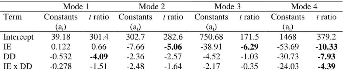
Table 4 Coefficients and t ratios for the natural frequencies (Hz)
Mode 1 Mode 2 Mode 3 Mode 4 Term Constants (ai) t ratio Constants (ai) t ratio Constants (ai) t ratio Constants (ai) t ratio Intercept 39.18 301.4 302.7 282.6 750.68 171.5 1468 379.2 IE 0.122 0.66 -7.66 -5.06 -38.91 -6.29 -53.69 -10.33 DD -0.532 -4.09 -2.36 -2.57 -4.52 -1.03 -30.73 -7.93 IE x DD -0.278 -1.51 -2.48 -1.64 -2.17 -0.35 -24.03 -4.39
Table 5 Coefficients and t ratios for damping ratios (%) estimated by Polymax (burst random testing) Mode 1 Mode 2 Mode 3 Mode 4
Term Constants (ai) t ratio Constants (ai) t ratio Constants (ai) t ratio Constants (ai) t ratio Intercept 0.617 12.26 0.206 20.15 0.339 7.28 0.392 45.24 IE 0.014 0.20 0.063 4.36 0.186 2.83 0.126 9.80 DD 0.151 3.00 0.026 2.20 0.043 0.92 0.066 7.64 IE x DD 0.007 0.10 0.008 1.26 0.016 1.03 0.046 1.74 By comparing the t ratios for the energy of impact (IE) and the density of damage (DD) in (tables 4 and 5), it can be seen that the energy of impact has a more significant effect on the modal parameters than the density of damage for the 2nd, 3rd and 4th bending modes. However, the density of damage is a more significant factor for the first bending mode. The second order interaction term (IE x DD) is in the majority of the cases insignificant as well.
From the design of experiments, it can be concluded that the energy of impact (IE) is the most significant factor on the natural frequencies and damping ratios (estimated by Polymax method with burst random excitation) for the 2nd, 3rd and 4th bending modes. If the t ratios for both the factors (IE and DD) are compared (table 4 and 5), it can be seen that the two factors (IE and DD) have higher t ratios for the natural frequencies. So it can be said that natural frequency is a better damage indicator than the damping ratio being more sensitive to the energy of impact and the density of damage.
5.Conclusion
Vibration tests have been carried out on pristine and damaged composite beam specimens using burst random and sine dwell excitations. The composite beam specimens are impacted with the help of a drop weight system by keeping in view the barely visible impact damage limit (BVID). Results show that with the accumulation of damage in the specimens, there is a decrease in natural frequency accompanied by an increase in damping ratio. Design of experiments carried out on the extracted modal parameters show that the natural frequency is a more sensitive parameter for damage detection than the damping ratio. Energy of impact is highlighted as the factor having the most significant effect on the modal parameters. Furthermore, the Half Bandwidth Method is found unsuitable for damping estimation in the presence of damage.
6.References
[1] Tay T 2001 Characterization and analysis of delamination fracture in composites Appl. Mech.
Rev 56 1-31
[2] Matthews F L 1999 Damage in fibre reinforced plastics; its nature, consequences and detection
Proc of DAMAS99 1-16
[3] Della C N and Shu D 2007 Vibration of delaminated composite laminates: A review Appl.
Mech. Rev 60 1-20
[4] Sanders D R, Kim Y I, and Stubbs N 1992 Non-destructive evaluation of damage in composite structures using modal parameters Exp. Mech. 32 240-251
[5] Zou Y, Tong L and Steven G B 2000 Vibration-based model-dependent damage (delamination) identification and health monitoring for composite structures. A review J. Sound Vib.
230 357-378
[6] Doebling S W, Farrar C R and Prime M B 1998 A summary review of vibration-based damage identification methods Shock Vib. Dig. 30 91-105
[7] Sohn H, Farrar C R, Hemez F M, Shunk D, Stinemates D W and Nadler B R 2003 A review of structural health monitoring literature: 1996-2001 Los Alamos National Laboratory Report LA-13976-MS
[8] Khoo L M, Mantena P R and Jadhav P 2004 Structural damage assessment using vibration modal analysis Struc. Health Monitoring 3(2) 177-194
[9] Yam L H and Cheng L 2005 Damage detection of composite structures using dynamic analysis.
K. Eng. Mat. 295-296 33-38
[10] Kim H Y and Hwang 2002 Effect of debonding on natural frequencies and frequency response functions of honeycomb sandwich beams Compos. Struct. 51 51-62
[11] Adams R D and Cawley P 1979 The localisation of defects in structures from measurements of natural frequencies J. Strain Anal. 14 49–57
[12] Richardson M H and Mannan M A 1993 Correlating minute structural faults with changes in modal parameters Proc. of SPIE 923(2) 893–898
[13] Li Z and Crocker M J 2006 Effect of thickness and delamination on the damping in honeycomb-foam sandwich beams J. Sound Vib. 192 977-993
[14] Adams R D 1993 Damping in composites Mater. Sci. Forum 119-121 3-16.
[15] Zhang Z and Hartwig G 2004. Relation of damping and fatigue damage of unidirectional fibre composites Int. J. Fatig. 24 713-738
[16] Gibson R F 2000 Modal vibration response measurements for characterization of composite materials and structures Compos. Sci. Tech. 60 2769-2780
[17] Saravanos D A and Hopkins D A 1995 Effects of delaminations on the damped dynamic characteristics of composites J. Sound Vib. 192 977-993
[18] Vanhoenacker K, Schoukens J, Guillaume P and Vanlanduit S 2004 The use of multisine excitations to characterise damage in structures Mech. Syst. Signal Process. 18 43-57
[19] Shahdin A, Morlier J and Gouriant Y Correlating low energy impact damage with changes in modal parameters: A preliminary study on composite beams Submitted Feb 08 to SHM [20] Wojtowicki J L and Jaouen L 2004 New approach for the measurements of damping properties
of materials using Oberst beamRev. Sci. Instrum. 75(8) 2569-2574
[21] Amraoui M Y and Lieven N A J 2004 Laser vibrometry based detection of delaminations in glass/epoxy composites J. Sound Vib. 126 430-437
[22] Yin H P 2008 A new theoretical basis for the bandwidth method and optimal power ratios for the damping estimation Mech. Syst. Signal. Process. 22(8) 1869-1881
[23] Petit S, Bouvet C, Bergerot A and Barrau J J 2007 Impact and compression after impact experimental study of a composite laminate with a cock thermal shield Compos. Sci. Tech.
67 3286-3299
[24] Meyers R H and Montgomery D C 1995 Response surface methodology (New York: Wiley)
Acknowledgments
The authors gratefully thank research project student Hanno Niemann from TU Braunschweig for his technical support during the experimental work