HAL Id: hal-02134689
https://hal.archives-ouvertes.fr/hal-02134689
Submitted on 21 Jan 2021HAL is a multi-disciplinary open access archive for the deposit and dissemination of sci-entific research documents, whether they are pub-lished or not. The documents may come from teaching and research institutions in France or abroad, or from public or private research centers.
L’archive ouverte pluridisciplinaire HAL, est destinée au dépôt et à la diffusion de documents scientifiques de niveau recherche, publiés ou non, émanant des établissements d’enseignement et de recherche français ou étrangers, des laboratoires publics ou privés.
A RECONFIGURABLE CHAOTIC CAVITY WITH
FLUORESCENT LAMPS FOR MICROWAVE
COMPUTATIONAL IMAGING
Ariel Christopher Tondo Yoya, Benjamin Fuchs, Cécile Leconte, Matthieu
Davy
To cite this version:
Ariel Christopher Tondo Yoya, Benjamin Fuchs, Cécile Leconte, Matthieu Davy. A RECONFIG-URABLE CHAOTIC CAVITY WITH FLUORESCENT LAMPS FOR MICROWAVE COMPUTA-TIONAL IMAGING. Progress In Electromagnetics Research, EMW Publishing, 2019. �hal-02134689�
A Reconfigurable Chaotic Cavity with Fluorescent Lamps for Microwave Computational Imaging
Ariel Christopher Tondo Yoya, Benjamin Fuchs, Cécile Leconte and Matthieu Davy Institut d’Electronique et de Télécommunications de Rennes, University of Rennes 1, Rennes 35042, France Emails : ariel.tondo.yoya.articc@gmail.com benjamin.fuchs@univ-rennes1.fr cecile.leconte@univ-rennes1.fr matthieu.davy@univ-rennes1.fr
Several computational imaging systems have recently been proposed at microwave and millimeter-wave frequencies enabling a fast and low cost reconstruction of the scattering strength of a scene. The quality of the reconstructed images is directly linked to the degrees of freedom of the system which are the number of uncorrelated radiated patterns that sequentially sample the scene. Frequency diverse antennas such as leaky chaotic cavities and metamaterial apertures take advantage of the spectral decorrelation of transmitted speckle patterns that stems from the reverberation within a medium. We present a reconfigurable chaotic cavity for which the boundary conditions can be tuned by exciting plasma elements, here commercial fluorescent lamps. The interaction of electromagnetic waves with a cold plasma is strongly modified as it is ionized. Instead of being transparent to incident waves, it behaves theoretically as a metallic material. The independent states of the cavity obtained using a differential approach further enhance the degrees of freedom. This relaxes the need of a cavity with a large bandwidth and/or high quality factor. Experimental results validate the use of fluorescent lamps and its limitations are discussed. Images of various metallic objects are provided to illustrate the potentialities of this promising solution.
I. Introduction
Computational Imaging (CI) techniques are of great interest to design fast, low-cost and high performances imaging systems [1-8]. Reconstructing images in real-time is especially crucial in the context of security screening [9, 10], through the wall imaging [11] or biomedical imaging [12, 13] with electromagnetic waves. The spatial content of a scene is collected onto a set of antenna positions in Synthetic Aperture Radar (SAR) and conventional antenna arrays,[14] whereas in CI it is encoded onto independent spatial patterns generated from only a few sensors. High resolution images are then reconstructed by solving an inverse problem using the knowledge of the sensing matrix between the sensors and the pixels to image.
In acoustics and for electromagnetic waves in microwave range, frequency-diverse antennas including leaky chaotic cavities [15-19] and metamaterial apertures [5, 20-23] exploit the reverberation within a high quality (𝑄) factor medium to generate spatially independent speckle patterns as a function of frequency [24-26]. A single shot measurement of the broadband impulse responses between the sensors is then sufficient to reconstruct the scene with a spatial resolution governed by the aperture diffraction limit similarly to SAR imaging. The properties are of the field in leaky chaotic cavities are of great interest in computational imaging to generate a random sensing matrix that can be inverted to solve the inverse problem. Thanks to the natural reverberation of waves within the medium, the pattern that
illuminates the scene is due to the radiation through the aperture of a spatially random wavefield which is correlated at the scale of a half wavelength. The statistics of the field can be described using wave chaos theory and exhibit universal properties [27-31]. The random wavefield with Gaussian statistics arises from the superposition of plane waves with random phases. It can be assumed as statistically isotropic and spatially uniform. The three polarization components are statistically equivalent within the chaotic cavity so that a single port can be used for computational polarimetric imaging [19, 32].
Independent speckle patterns are radiated from the aperture as the excitation frequency is swept. The spectral correlation length 𝛿𝜔 gives the average spectral spacing between two uncorrelated patterns. It is inversely proportional to the reverberation time of the waves within the cavity 𝜏, 𝛿𝜔 = 1/𝜏. The spectral length 𝛿𝜔 is related to the 𝑄 factor by 𝑄 = 𝜔0/𝛿𝜔, where 𝜔0 is the angular central frequency.
The number of spectral degrees of freedom 𝑁𝜔 provided by frequency diverse-antennas is then given
by the number of independent states within the working bandwidth Δ𝜔, 𝑁𝜔= Δ𝜔/𝛿𝜔 = 𝑄Δ𝜔/𝜔0. The
signal-to-noise ratio (SNR) of the reconstructed images directly depends on 𝑁𝜔. The same principle is
underlying time-reversal focusing within disordered media which makes it possible to focus waves at the diffraction limit with a single antenna [33].
The reconstruction of an image requires the knowledge of the sensing matrix giving the transmission coefficients between the sensors and the scene. To build this matrix, the spectra of radiated field on the scene can for instance be obtained by scanning the near-field of the cavity and propagating this field onto the scene. Achieving high imaging performances requires frequency-diverse antennas with a high number of degrees of freedom. These are antennas with a large bandwidth and/or a high 𝑄-factor. However, a trade-off exists between the radiated power toward the scene and the imaging quality. A large aperture indeed increases the radiated power but at the cost of a reduced 𝑄-factor due to radiative losses through the aperture [18]. This hence limits the number of spectral degrees of freedom. The SNR is therefore maximized for an optimized aperture.
In this context, another possibility to obtain new degrees of freedom at a single frequency is to change the boundary conditions of the cavity. Those new states can be achieved mechanically and/or electronically. In reverberation chambers, statistically independent measurements are obtained using the rotation of mode-stirrer which consists of metallic reflectors such as paddle wheels [34]. However, the slow rotation of the paddles may be a concern for real-time imaging applications. Electrically tuning the boundary conditions have shown great promise recently. Sleasman et al. designed a disordered cavity with a wall replaced by a tunable-impedance boundary for which the reflection phase of each element can be modified using a voltage bias [17]. The unit cell is a resonator with two operating states and the incoming wave is reflected with phase shifts typically close to 0 or π over a frequency range of 4 GHz around 20 GHz. A similar tunable metasurface [35], a so-called spatial microwave modulator (SMM), has been employed to control wave propagation within reverberating media over a bandwidth of 100 MHz [36, 37]. The intensity in a reverberation medium can be strongly enhanced at a point by shaping the phase pattern of the SMM so that waves arising from the metasurface interfere constructively at this selected point [36]. In a closed cavity, the SMM also enables to tune the resonances of the cavity in the regime for which the resonance weakly overlap [37]. Nevertheless the bandwidth associated to techniques based on the use of resonators to change boundary conditions is inherently limited since it depends on the linewidth of the resonance.
In this paper, we present a simple and low-cost reconfigurable chaotic cavity for which the boundary conditions are tuned by switching on and off commercial fluorescent lamps (FL). A FL is a plasma column which is almost transparent to waves when it is not excited but becomes a scattering object as the gas is electrically charged. We use this effect to obtain new states of a chaotic cavity and increase the number of degrees of freedom at a single frequency. Because FLs are lossy objects, we explore the resulting decrease of the 𝑄-factor as a function of the number of excited FLs. We then investigate the correlation of speckle patterns for the different states of the cavity. We show that even though the interaction of electromagnetic waves around the plasma frequency with commercial FLs is weak, a differential approach yields an effective number of independent states which greatly enhances the total number of degrees of freedom. We finally demonstrate imaging of metallic objects outside the cavity using computational techniques.
II.
Reconfigurable Chaotic Cavity
The use of plasma tubes to tune the properties of a system in the microwave range is of great interest due to its simple implementation and the large bandwidth that can be considered. The relative dielectric constant of an excited plasma and the angular frequency are theoretically given in the Drude model [38] by 𝜖𝑟= 1 −
𝜔𝑝2
𝜔(𝜔+𝑖𝜈) and 𝜔𝑝= √ 𝑛𝑒𝑒2
𝜖0𝑚𝑒, respectively. Here 𝑛𝑒 is the number density of electrons, 𝜖0 is the permittivity of free space, 𝑒 and 𝑚𝑒 are the charge and electron mass, and 𝜈 is the
electron-neutral collision frequency. For 𝜔 > 𝜔𝑝, an excited plasma has the properties of a dielectric material
but at frequencies smaller than the plasma frequency (𝜔 < 𝜔𝑝), we obtain 𝜖𝑟 < 0 so that the plasma can
be considered as a lossy metal. For 𝜔𝑝≫ 𝜈, the conductivity 𝜎 = 𝜖0𝜔𝑝2/𝜈 of a densely ionized plasma
below the plasma frequency is high.
Replacing metallic pieces of traditional antennas by plasma columns makes it possible to design efficient reconfigurable systems.[39] Some successful demonstrations include plasma antennas with low radar cross-sections which are almost undetectable when the plasma is turned off [40], reconfigurable metamaterials [41-43], tunable leaky-wave antennas [44, 45] and frequency agile resonators [46].
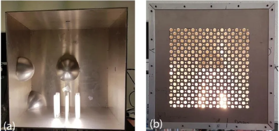
Six FLs are located inside an aluminum leaky cavity (see Fig. 1). The cavity of outer dimensions 50x50x30 cm3 is made chaotic by adding three hemispheres inside. Two coaxial to waveguide
transitions are attached to two sides of the cavity. The details of the cavity are given in Ref [19]. To change the boundary conditions, the FLs are controlled with an Arduino. 𝑁𝑠= 64 states can therefore
be achieved. Measurements reported in Ref. [47] of similar commercial FLs in transmission and reflection lead to an estimation of the plasma frequency 𝑓𝑝= 𝜔𝑝/(2𝜋) around 7 GHz. We choose the
frequency range between 7.5 and 8.5 GHz. Even though this is slightly higher than the plasma frequency, this guarantees a cm-resolution since the wavelength at the center frequency 𝑓𝑐 = 8 GHz is 𝜆 ∼
3.75 cm.
Fig. 1: Photography of the cavity without (a) and with (b) the front face made of drilled holes. The FLs inside can be separately excited using an Arduino.
To illuminate the scene, an array of 11x11 holes of diameter 12.5 mm are perforated on the front face of the cavity. Note that a second array of subwavelength holes with diameter 𝜆/18 has been drilled but they contribute very weakly to radiations in this frequency range. The near-field of this aperture is scanned on 601 frequency points with an Intermediate Filter bandwidth of 10 kHz on a grid with a spacing of 𝜆/3 in both sides. For each position of the probe 𝒓𝐴, we measure successively the
transmission coefficients for the 𝑁𝑠 states, ℎ𝑖(𝒓𝐴, 𝜔). The scanning time of the aperture is about 6h.
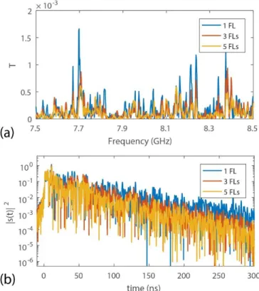
Spectra of the transmitted intensity through the aperture and their inverse Fourier transform are shown in Fig. 2a for different states. The time signals, which are the responses to 1-ns incident pulses, are spreading over more than 300 ns (see Fig. 2b) due to the reverberation within the cavity. We observe that the intensity decays more rapidly with time when a large number of FLs is excited.
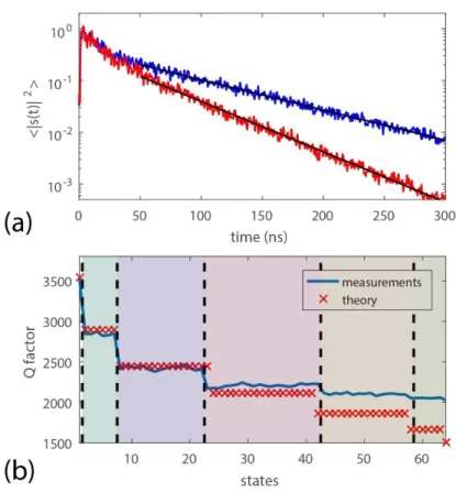
We first explore the 𝑄-factor of the cavity as a function of the number of FLs that are excited. To this end, we compute the inverse Fourier transform of the near-field spectra and fit the radiated intensity in the time domain with an exponential decay, 〈|𝑠(𝑡)|2〉 ∼ exp (−𝑡/𝜏). 〈|𝑠(𝑡)|2〉 and the exponential decay
are shown in Fig. 3a for two states when one and three FLs are turned on, respectively. 𝑄 is then found from the formula 𝑄 = 2𝜋𝑓𝑐𝜏. It is seen in Fig. 3b that 𝑄 decreases from 3700 to 2000 as a function of
the number of excited FLs. The permittivity of the plasma is indeed complex and its imaginary part is responsible of additional losses within the cavity. The quality factor 𝑄 can be estimated by 𝑄−1=
𝑄0−1+ 𝑁𝑄𝐹𝐿−1,[48] where 𝑄0 is the quality factor associated to the “unloaded” cavity when all the plasma
elements are turned off, 𝑄𝐹𝐿 is the quality factor associated to a single plasma element and 𝑁 is the
number of activated plasma elements. Those two parameters can be estimated with 𝑁 = 0 and 𝑁 = 1. A theoretical curves is compared to the experimental result in Fig. 3b. A good agreement for a small number of activated elements is found but a strong deviation is observed for 𝑁 ≥ 4. One possible explanation is that the FLs are close to each other whereas the model is valid for absorbers that are randomly distributed within the cavity. Additional elements may therefore only weakly increase absorption because the wave entering the area including the FLs is already strongly absorbed.
Fig. 2: (a) Spectra of transmission coefficients between the first port of the cavity and a point in the near-field of the cavity for three different states corresponding to one, three and five FLs that are turned on. (b) Transmitted intensity in time-domain for these three different states.
Fig. 3: (a) Plot of the transmitted intensity in time-domain averaged over the near-field of the aperture for 1 (blue line) and 3 (red line) FLs that are turned on. The black lines are exponential fits, 〈𝐼(𝑡)〉 = 𝑒−𝑡𝜏. (b) Q factor found from reverberation times τ as a function of the state. The number of FLs that are turned on is indicated by upper horizontal numbers.
The generation of new configurations of the cavity strongly relaxes the need of a high 𝑄-factor for high performances imaging. The total number of degrees of freedom 𝑁 is theoretically given by the product of the number of transmitting/receiving antennas 𝑁ant, the number of spectral degrees of
freedom 𝑁𝜔, and the number of independent states generated at a single frequency by changing the
boundary conditions 𝑁eff, 𝑁 = 𝑁ant𝑁𝜔𝑁eff.
To investigate the number of independent states 𝑁eff, we compute the correlation coefficient between
the spatial vectors of output near-field scans ℎ𝑖(𝒓𝐴, 𝜔). Since the sensing matrix is built from the
projection of the near-field scans on the scene, the rank of the covariance matrix built upon those coefficients gives 𝑁eff. The magnitude of the correlation coefficient between states 𝑖 and 𝑗 is defined as
𝐶𝑖𝑗(𝜔) = |∫ ℎ𝒓𝐴 𝑗∗(𝒓𝐴,𝜔)ℎ𝑖(𝒓𝐴,𝜔)𝑑𝑟| √∫ |ℎ𝒓𝐴 𝑖(𝒓𝐴,𝜔)|2𝑑𝑟√∫ |ℎ𝑗(𝒓𝐴,𝜔)| 2 𝒓𝐴 𝑑𝑟 . (1)
The covariance matrix averaged over the frequency range, 〈𝑪(𝜔)〉𝜔, is shown in Fig. 4a. In contrast
to the case of perfectly uncorrelated states that would lead to a diagonal covariance matrix, it is seen that the off-diagonal coefficients cannot be neglected. We find 〈𝑪𝑖≠𝑗(𝜔)〉 ∼ 0.75. This degree of
correlation is also illustrated by the impulse responses for different cavity states. We observe in Fig. 4(c) that those responses are almost identical at short time (𝑡 < 20 ns) and exhibit significant variations only for 𝑡 > 80 ns.
Fig. 4: (a,b) Covariance matrix as a function of the state number averaged over the frequency range for (a) near-field scan and (b) the differential approach (the field averaged over the states is subtracted). (c,d) Plot of the transmitted intensity in the time domain for (c) the near-field scan and (d) the differential approach. The averaging of 〈𝑠𝑖(𝑡)〉𝑖 is performed on the 64 states of the cavity.
We define the participation number of eigenvalues 𝜏𝑛 of the covariance matrix as 𝑁eff =
(Σ𝑛=1𝑁𝑆 𝜏 𝑛) 2 /Σ𝑛=1𝑁𝑆 𝜏 𝑛 2. 𝑁
eff reflects the distribution of the eigenvalues 𝜏𝑛 of the covariance matrix. It gives
the effective number of independent states that can be generated and therefore the corresponding degrees of freedom of the reconfigurable cavity at a single frequency. In a phase-conjugation experiment, 𝑁eff
is equal to the contrast between the focused energy and the background for focusing at a point outside the cavity [49-51]. Speckle patterns with a vanishing degree of correlation would give a diagonal covariance matrix and 𝑁eff= 𝑁𝑠= 64. Here we find 𝑁eff = 1.5. The reason of this small 𝑁eff is
twofold: 1) the frequency range has been chosen around the plasma frequency and not lower and 2) commercial FLs excited with an almost steady state current are poor reflectors even when 𝜔 < 𝜔𝑝. It
means that the incident field is hence not scattered enough by an excited FL to fully scramble the propagation of waves inside the cavity.
The field radiated from the aperture can be decomposed as the sum of the field that has been transmitted without being scattered by the FL, ℎ0(𝒓𝐴, 𝜔), and the scattered contribution in the ith state
of the cavity, ℎ𝑖𝑠(𝒓𝐴, 𝜔), ℎ𝑖(𝒓𝐴, 𝜔) = ℎ0(𝒓𝐴, 𝜔) + ℎ𝑖𝑠(𝒓𝐴, 𝜔). We estimate the coherent contribution
ℎ0(𝒓𝐴, 𝜔) as the average of the output field over the 𝑁𝑠 states, ℎ0(𝒓𝐴, 𝜔) ∼ 〈ℎ𝑖(𝒓𝐴, 𝜔)〉𝑖. For an
electrically large chaotic cavity with perfect plasma behaving as transparent/metallic elements with lengths longer than 𝜆/2, one would expect that ℎ0 could be neglected, 〈|ℎ0(𝒓𝐴, 𝜔)|2〉 ≪ 〈|ℎ𝑖𝑠(𝒓𝐴, 𝜔)|2〉.
However we find 〈|ℎ0(𝒓𝐴, 𝜔)|2〉 = 4.5〈|ℎ𝑖𝑠(𝒓𝐴, 𝜔)|2〉 which confirms that the scattering coefficient of
the plasma tubes is weak. The conductivity of excited FLs is hence likely to be small in comparison to metallic objects. In summary, the propagation of waves within the cavity is only slightly modified by the excitation of the FLs.
A differential approach is proposed to remove the contribution that is robust to the average over the states of the cavity. Note that such a differential approach has been used in the context of localization of objects in disordered cavities.[52] We consider the so-corrected patterns ℎ̃𝑖(𝒓𝐴, 𝜔) = ℎ𝑖(𝒓𝐴, 𝜔) −
〈ℎ𝑖(𝒓𝐴, 𝜔)〉𝑖. The covariance matrix computed from ℎ̃𝑖(𝒓𝐴, 𝜔) is seen in Fig. 4b to be nearly diagonal.
𝑁eff is then greatly enhanced and found to be 11.5. This procedure mainly removes the coherent field
ℎ0(𝒓𝐴, 𝜔) and strong variations between time signals for different states are now seen in Fig. 4(d) even
at short times. Nevertheless, the price to pay is a reduction of the measurement sensitivity. The signal-to-noise ratio (SNR) of the sensing matrix can be defined as 𝑆 = 〈|ℎ0(𝑟, 𝜔)|2〉/𝜎𝑛2, where 𝜎𝑛2 is the
variance of the noise. Here we estimate that the SNR is reduced by about 7.4dB when the coherent field is removed.
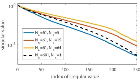
To assess the impact of the FLs on the number of degrees of freedom of the cavity, we compute the singular value decomposition of the sensing matrix of the cavity. In Fig. 5, the distribution of normalized singular values 𝜆̃𝑛= 𝜆𝑛/𝜆1 is shown for 𝑁𝜔=61 and different numbers of states that are randomly
chosen over the 64 available states. For 𝑛 < 205, it is seen that the distribution of 𝜆̃𝑛 is more flat as 𝑁𝑠
increases. This indicates that the number of uncorrelated speckle patterns also increases. However, we observe that the slope saturates as 𝑁𝑠> 15. It is possible to select appropriately only a few states among
the 64 in order to maximize 𝑁eff. By using a standard genetic algorithm, we have selected only 12 states
and managed to achieve 𝑁eff= 7.8. The total degrees of freedom is then 𝑁 = 𝑁𝜔𝑁eff= 476.
This can be compared to the case of an unloaded cavity with a quality factor 𝑄 = 3700 and the full frequency range 𝑁𝜔= 601. This gives a number of degrees of freedom 𝑁 = 𝑁𝜔= 128 which is smaller
by a factor 3.7. The singular values are seen to decrease faster to the case 𝑁𝑠= 15 and 𝑁𝜔= 61. This
highlights that the degrees of freedom are enhanced by the new reconfigurable states even though the number of frequencies has been strongly reduced and the quality factor decreases as more FLs are introduced. This demonstrates that plasma elements can be used to modify the boundary conditions of the cavity and enhance the degrees of freedom provided by a leaky cavity.
Nevertheless, in all cases, the distribution of singular values falls rapidly for 𝑛 > 205. The number of significant singular values is indeed bounded due to the dimensions of the aperture 𝐴 = 0.09 m². The maximum number of independent states is 𝐴/(𝜆/2)2. Here we find 𝐴/(𝜆/2)2= 225, where 𝜆 is the
wavelength corresponding to the smallest frequency, which is in good agreement with the index of the break in the slope.
Fig. 5: Variation of the normalized singular values of the sensing matrix of the cavity with their index for different number of states 𝑁𝑠 taken into account and 𝑁𝜔 = 61 frequencies chosen randomly within
the bandwidth. These variations are compared to the “unloaded” case 𝑁𝑠= 1 for which all the FLs are
switched off but the entire frequency range is used, 𝑁𝜔= 601.
The scene is illuminated by a horn antenna polarized along the z-axis similarly to the scan of the cavity. The horn antenna is located 40 cm away from the center of the cavity. The back-scattered signal is then recorded by the port of the cavity. We assume in the following the first order Born approximation. The signal received by the cavity at state i can be written as[32]
𝑦𝑖(𝜔) = ∫ 𝑬𝒓 𝑇(𝒓, 𝜔) 𝜒̅(𝑟)𝑬𝑖𝑇(𝒓, 𝜔)𝑑𝒓 (2)
Here 𝜒̅(𝒓) is the susceptibility tensor at point 𝒓 in the illuminated domain, 𝑬𝑇(𝒓, 𝜔) is the transmitted
field from the horn antenna and 𝑬𝑖(𝒓, 𝜔) is the radiated field from the leaky chaotic cavity at state i.
Here we aim to reconstruct the component of 𝜒̅(𝒓) which corresponds to the polarization of transmitted field from the horn antenna, 𝑥(𝒓) = 𝜒𝑧𝑧(𝒓). To this end, the electric field along z, 𝐸𝑇(𝒓, 𝜔), can be
estimated from the position of the horn antenna with 𝐸𝑇(𝒓, 𝜔) ∝ 𝐺(𝒓𝑇, 𝒓, 𝜔), where 𝐺(𝒓𝑇, 𝒓, 𝜔) is the
Green’s functions between 𝒓𝑇 and 𝒓. We then express the electric field 𝑬𝑖(𝒓, 𝜔) in terms of the current
distribution 𝑱𝑖(𝒓𝐴, 𝜔) on the aperture of the cavity is[32]
𝑬𝑖(𝒓, 𝜔) = 𝑗𝜔𝜇0∫ 𝑑𝒓𝒓 𝑇,𝑅𝑱𝑖(𝒓𝐴, 𝜔)𝐺̅(𝒓𝐴, 𝒓, 𝜔)
𝐴 . (3)
𝐺̅(𝒓𝐴, 𝒓, 𝜔) is the dyadic Green function between 𝒓𝐴 and 𝒓. Because the measured near-field scan on the
cavity aperture is proportional to the current distribution along the z-axis, ℎ𝑖(𝒓𝐴, 𝜔) ∝ 𝐽𝑖𝑧(𝒓𝐴, 𝜔), the
received signal is proportional to
𝑦𝑖(𝜔) ∝ ∬𝒓 𝑑𝒓𝐴
𝑑𝒓𝐺
(𝒓𝑇, 𝒓, 𝜔)𝐺
(𝒓𝐴, 𝒓, 𝜔)𝑥(𝒓)ℎ𝑖(𝒓𝐴, 𝜔)𝐴,𝒓 (4)
Imaging the scene consists in reconstructing the spatial content of 𝑥(𝒓). We compute the sensing matrix 𝑯 in the imaging plane from
𝐻𝑖(𝒓, 𝜔) = ∫ 𝑑𝒓𝒓 𝐴
𝐺
(𝒓𝑇, 𝒓, 𝜔)𝐺
(𝒓𝐴, 𝒓, 𝜔)ℎ𝑖(𝒓𝑎, 𝜔)𝐴 (5)
Furthermore, we have previously seen that the differential approach is greatly enhancing the available degrees of freedom at a single frequency. We therefore solve the following discretized equation
𝐲 − 〈𝐲〉i= (𝐇 − 〈𝐇〉i) 𝒙 . (6)
Here 𝒚 is the measurement vector including all the frequencies and all the cavity states, 𝐇 is the corresponding sensing matrix between the emission/reception and the pixels at which 𝒙 is reconstructed. We subtract at each frequency the average values over the cavity states: 〈𝐲〉i for the observation vector
and 〈𝐇〉i for the sensing matrix.
We discretize the scene with square pixels of dimensions 𝜆/6 x 𝜆/6 and solve Eq. (6) to reconstruct objects located at a distance 𝑧 =52 cm from the aperture of the cavity. We use 𝑁𝜔= 61 frequencies
and 𝑁𝑠= 12 states. The images in the plane of objects of a sphere, two spheres, a metallic bottle and a
L-shaped phantom are shown in Fig. 6. To invert the matrix (𝐇 − 〈𝐇〉i), we first perform a truncated
singular value decomposition and then apply a total variation norm regularizer.[53] The SNR of the images defined as the maximum of the target over the maximum of the background are 33 dB, 28 dB, 16 dB and 8 dB respectively. A 3D reconstruction of the two spheres is also shown in Fig. 6e. The resolution in range is now given by 𝑐0/2𝐵 [54, 55], where 𝐵 is the bandwidth. Here the 𝑁𝜔 frequencies
are chosen to span the frequency range so that 𝐵 = 1 GHz, giving a theoretical resolution of 3cm along the z-direction.
The good reconstruction of the shape of the objects demonstrates the capability of our system to image metallic objects with a resolution of ∼ 5 cm in the (x-y) plane. This also confirms the validity of the differential approach for computational imaging with our reconfigurable cavity.
Fig. 6: (a) Reconstructed images of 4 objects at a distance of 52 cm from the aperture of the leaky cavity with Nf=61 and Ns=12: a single (a) and two spheres (b) of 5-cm diameter; (c) a metallic bottle of height
25 cm and diameter 9 cm; and (d) a metallic L-shaped phantom. (e) 3D reconstruction of the two spheres shown in (b).
IV.
Conclusion
We have demonstrated the design of a reconfigurable leaky cavity for microwave computation imaging using commercial FLs. Thanks to the remarkable properties of cold plasma regarding the interaction with microwaves below the plasma frequency, new states of the leaky cavity can be generated at a single frequency by exciting plasma columns. This strongly increases the available degrees of freedom that are crucial to reconstruct a scene using computational techniques. At a given SNR, introducing new states by changing the boundary conditions of frequency diverse antennas enables to reduce the frequency range of measurements and/or consider new systems with smaller 𝑄 factor. In contrast to tunable metasurfaces designed using resonators, the frequency range over which new states of the cavity can be generated in principle spans the complete frequency range below the plasma frequency but at the cost of a quality factor 𝑄 which decreases with the number of excited lamps.
Nevertheless we have shown that an excited commercial FL is far from behaving as a metallic object. The reflection of waves at its interface is weak and this leads to a small number of independent states and a reduced 𝑄 factor. However, we have considered a differential approach to remove the coherent part of the field and achieve a high effective number of independent states. Our low-cost system, that is intended to be a proof of concept, could be largely improved by using more sophisticated plasma columns with higher electron density to 1) reduce the losses of the excited columns; and 2) increase the
plasma frequency so that higher frequency ranges can be considered. Measurements of efficiencies up to 50% have been reported for plasma column elements in comparison to similar metallic objects [31]. Additional independent states could therefore be obtained without resorting to the differential approach and this would further improve the SNR of the imaging process.
Acknowledgment
The authors would like to thank Frédéric Boutet and Jean-Christophe Le Cun for their help in setting up the experiment.
References
[1] M. F. Duarte, M. A. Davenport, D. Takhar, J. N. Laska, T. Sun, K. E. Kelly, and R. G. Baraniuk, "Single-pixel imaging via compressive sampling," IEEE Signal Process. Lett., vol. 25, p. 83, 2008.
[2] W. L. Chan, K. Charan, D. Takhar, K. F. Kelly, R. G. Baraniuk, and D. M. Mittleman, "A single-pixel terahertz imaging system based on compressed sensing," Appl. Phys. Lett., vol. 93, p. 121105, 2008.
[3] O. Katz, Y. Bromberg, and Y. Silberberg, "Compressive ghost imaging," Appl. Phys. Lett., vol. 95, p. 131110, 2009.
[4] B. Sun, M. P. Edgar, R. Bowman, L. E. Vittert, S. Welsh, A. Bowman, and M. Padgett, "3D computational imaging with single-pixel detectors," Science, vol. 340, pp. 844-847, 2013. [5] J. Hunt, T. Driscoll, A. Mrozack, G. Lipworth, M. Reynolds, D. Brady, and D. R. Smith,
"Metamaterial apertures for computational imaging," Science, vol. 339, pp. 310-313, 2013. [6] O. Katz, P. Heidmann, M. Fink, and S. Gigan, "Non-invasive single-shot imaging through
scattering layers and around corners via speckle correlations," Nat. Photonics, vol. 8, pp. 784-790, 2014.
[7] A. Liutkus, D. Martina, S. Popoff, G. Chardon, O. Katz, G. Lerosey, S. Gigan, L. Daudet, and I. Carron, "Imaging with nature: Compressive imaging using a multiply scattering medium,"
Sci. Rep., vol. 4, 2014.
[8] C. M. Watts, D. Shrekenhamer, J. Montoya, G. Lipworth, J. Hunt, T. Sleasman, S. Krishna, D. R. Smith, and W. J. Padilla, "Terahertz compressive imaging with metamaterial spatial light modulators," Nat. Photonics, vol. 8, pp. 605-609, 2014.
[9] D. M. Sheen, D. L. McMakin, and T. E. Hall, "Three-dimensional millimeter-wave imaging for concealed weapon detection," IEEE Trans. Microw. Theory Tech., vol. 49, pp. 1581-1592, 2001. [10] H.-M. Chen, S. Lee, R. M. Rao, M.-A. Slamani, and P. K. Varshney, "Imaging for concealed weapon detection: a tutorial overview of development in imaging sensors and processing," IEEE
Signal Process. Mag., vol. 22, pp. 52-61, 2005.
[11] E. J. Baranoski, "Through-wall imaging: Historical perspective and future directions," J.
Franklin Inst., vol. 345, pp. 556-569, 2008.
[12] E. C. Fear, X. Li, S. C. Hagness, and M. A. Stuchly, "Confocal microwave imaging for breast cancer detection: Localization of tumors in three dimensions," IEEE Trans. Biomed. Eng., vol. 49, pp. 812-822, 2002.
[13] N. K. Nikolova, "Microwave imaging for breast cancer," IEEE microw. mag., vol. 12, pp. 78-94, 2011.
[14] J. Li and P. Stoica, MIMO Radar Signal Processing: Wiley Online Library, 2008.
[15] G. Montaldo, D. Palacio, M. Tanter, and M. Fink, "Building three-dimensional images using a time-reversal chaotic cavity," IEEE Trans. Ultrason., Ferroelect., Freq. Control, vol. 52, pp. 1489-1497, 2005.
[16] O. Yurduseven, V. R. Gowda, J. N. Gollub, and D. R. Smith, "Printed Aperiodic Cavity for Computational and Microwave Imaging," IEEE Microw. Wirel. Compon. Lett., vol. 26, pp. 367-369, 2016.
[17] T. Sleasman, M. F. Imani, J. N. Gollub, and D. R. Smith, "Microwave Imaging Using a Disordered Cavity with a Dynamically Tunable Impedance Surface," Phys. Rev. Applied, vol. 6, p. 054019, 2016.
[18] T. Fromenteze, O. Yurduseven, M. F. Imani, J. Gollub, C. Decroze, D. Carsenat, and D. R. Smith, "Computational imaging using a mode-mixing cavity at microwave frequencies," Appl.
Phys. Lett., vol. 106, p. 194104, 2015.
[19] A. C. Tondo Yoya, B. Fuchs, and M. Davy, "Computational passive imaging of thermal sources with a leaky chaotic cavity," Appl. Phys. Lett., vol. 111, p. 193501, 2017/11/06 2017.
[20] T. Zvolensky, J. N. Gollub, D. L. Marks, and D. R. Smith, "Design and analysis of a W-band metasurface-based computational imaging system," IEEE Access, vol. PP, pp. 1-1, 2017. [21] J. N. Gollub, O. Yurduseven, K. P. Trofatter, D. Arnitz, M. F. Imani, T. Sleasman, M. Boyarsky,
A. Rose, A. Pedross-Engel, H. Odabasi, T. Zvolensky, G. Lipworth, D. Brady, D. L. Marks, M. S. Reynolds, and D. R. Smith, "Large Metasurface Aperture for Millimeter Wave Computational Imaging at the Human-Scale," Sci. Rep., vol. 7, p. 42650, 2017.
[22] T. Fromenteze, X. Liu, M. Boyarsky, J. Gollub, and D. R. Smith, "Phaseless computational imaging with a radiating metasurface," Opt. Express, vol. 24, pp. 16760-16776, 2016/07/25 2016.
[23] T. Sleasman, M. F. Imani, J. N. Gollub, and D. R. Smith, "Dynamic metamaterial aperture for microwave imaging," Appl. Phys. Lett., vol. 107, p. 204104, 2015/11/16 2015.
[24] O. Yurduseven, J. N. Gollub, D. L. Marks, and D. R. Smith, "Frequency-diverse microwave imaging using planar Mills-Cross cavity apertures," Opt. Express, vol. 24, pp. 8907-8925, 2016/04/18 2016.
[25] D. L. Marks, J. Gollub, and D. R. Smith, "Spatially resolving antenna arrays using frequency diversity," JOSA A, vol. 33, pp. 899-912, 2016.
[26] O. Yurduseven, V. R. Gowda, J. N. Gollub, and D. R. Smith, "Multistatic microwave imaging with arrays of planar cavities," IET Microwaves, Antennas & Propagation, vol. 10, pp. 1174-1181, 2016.
[27] H. J. Stöckmann, Quantum Chaos: An Introduction. Cambridge: Cambridge University Press, 1999.
[28] U. Kuhl, O. Legrand, and F. Mortessagne, "Microwave experiments using open chaotic cavities in the realm of the effective Hamiltonian formalism," Fortschritte der Physik, vol. 61, pp. 404-419, 2013.
[29] G. Gradoni, J.-H. Yeh, B. Xiao, T. M. Antonsen, S. M. Anlage, and E. Ott, "Predicting the statistics of wave transport through chaotic cavities by the random coupling model: A review and recent progress," Wave Motion, vol. 51, pp. 606-621, 2014.
[30] B. Dietz and A. Richter, "Quantum and wave dynamical chaos in superconducting microwave billiards," Chaos, vol. 25, p. 097601, 2015.
[31] J. B. Gros, U. Kuhl, O. Legrand, and F. Mortessagne, "Lossy chaotic electromagnetic reverberation chambers: Universal statistical behavior of the vectorial field," Phys. Rev. E, vol. 93, p. 032108, 2016.
[32] T. Fromenteze, O. Yurduseven, M. Boyarsky, J. Gollub, D. L. Marks, and D. R. Smith, "Computational polarimetric microwave imaging," Opt. Express, vol. 25, pp. 27488-27505, 2017.
[33] C. Draeger and M. Fink, "One-Channel Time Reversal of Elastic Waves in a Chaotic 2D-Silicon Cavity," Phys. Rev. Lett., vol. 79, pp. 407-410, 1997.
[34] P. Besnier and B. Démoulin, Electromagnetic reverberation chambers: John Wiley & Sons, 2013.
[35] N. Kaina, M. Dupré, M. Fink, and G. Lerosey, "Hybridized resonances to design tunable binary phase metasurface unit cells," Opt. Express, vol. 22, pp. 18881-18888, 2014/08/11 2014. [36] N. Kaina, M. Dupré, G. Lerosey, and M. Fink, "Shaping complex microwave fields in
reverberating media with binary tunable metasurfaces," Sci. Rep., vol. 4, p. 6693, 2014. [37] M. Dupré, P. del Hougne, M. Fink, F. Lemoult, and G. Lerosey, "Wave-Field Shaping in
Cavities: Waves Trapped in a Box with Controllable Boundaries," Phys. Rev. Lett., vol. 115, p. 017701, 2015.
[38] M. A. Lieberman and A. J. Lichtenberg, Principles of plasma discharges and materials
processing: John Wiley & Sons, 2005.
[39] J. Sokoloff, O. Pascal, T. Callegari, R. Pascaud, F. Pizarro, L. Liard, J. Lo, and A. Kallel, "Non-thermal plasma potentialities for microwave device reconfigurability," C. R. Phys., vol. 15, pp. 468-478, 2014/05/01/ 2014.
[40] G. G. Borg, J. H. Harris, D. G. Miljak, and N. M. Martin, "Application of plasma columns to radiofrequency antennas," Appl. Phys. Lett., vol. 74, pp. 3272-3274, 1999/05/31 1999.
[41] S. Osamu and T. Kunihide, "Plasmas as metamaterials: a review," Plasma Sources Sci. Technol., vol. 21, p. 013001, 2012.
[42] J. Lo, J. Sokoloff, T. Callegari, and J. P. Boeuf, "Reconfigurable electromagnetic band gap device using plasma as a localized tunable defect," Appl. Phys. Lett., vol. 96, p. 251501, 2010/06/21 2010.
[43] A. Alù, F. Bilotti, N. Engheta, and L. Vegni, "Subwavelength, compact, resonant patch antennas loaded with metamaterials," IEEE Trans. Ant. Prop., vol. 55, pp. 13-25, 2007.
[44] I. Bahl and K. Gupta, "A leaky-wave antenna using an artificial dielectric medium," IEEE Trans.
Ant. Prop., vol. 22, pp. 119-122, 1974.
[45] G. Lovat, P. Burghignoli, F. Capolino, D. R. Jackson, and D. R. Wilton, "Analysis of directive radiation from a line source in a metamaterial slab with low permittivity," IEEE Trans. Ant.
Prop., vol. 54, pp. 1017-1030, 2006.
[46] V. Laquerbe, R. Pascaud, T. Callegari, L. Liard, and O. Pascal, "Frequency-agile microstrip resonator using DC plasma discharge," Electron. Lett., vol. 53, pp. 415-417, 2017.
[47] O. A. Barro, O. Lafond, and H. Himdi, "Reconfigurable antennas radiations using plasma Faraday cage," in 2015 International Conference on Electromagnetics in Advanced
Applications (ICEAA), 2015, pp. 545-548.
[48] L. R. Arnaut, "Statistics of the quality factor of a rectangular reverberation chamber," IEEE
Trans. Elec. Comp., vol. 45, pp. 61-76, 2003.
[49] M. Davy, Z. Shi, and A. Z. Genack, "Focusing through random media: Eigenchannel participation number and intensity correlation," Phys. Rev. B, vol. 85, p. 035105, 2012.
[50] M. Davy, Z. Shi, J. Wang, and A. Z. Genack, "Transmission statistics and focusing in single disordered samples," Opt. Express, vol. 21, pp. 10367-10375, 2013.
[51] C. W. Hsu, S. F. Liew, A. Goetschy, H. Cao, and A. D. Stone, "Correlation-enhanced control of wave focusing in disordered media," Nat. Phys., vol. 13, p. 497, 2017.
[52] P. del Hougne, M. F. Imani, M. Fink, D. R. Smith, and G. Lerosey, "Precise Localization of Multiple Noncooperative Objects in a Disordered Cavity by Wave Front Shaping," Phys. Rev.
Lett., vol. 121, p. 063901, 2018.
[53] L. I. Rudin, S. Osher, and E. Fatemi, "Nonlinear total variation based noise removal algorithms,"
Physica D, vol. 60, pp. 259-268, 1992.
[54] K. B. Cooper and G. Chattopadhyay, "Submillimeter-wave radar: Solid-state system design and applications," IEEE microw. mag., vol. 15, pp. 51-67, 2014.
[55] O. Yurduseven, M. F. Imani, H. Odabasi, J. Gollub, G. Lipworth, A. Rose, and D. R. Smith, "Resolution of the Frequency Diverse Metamaterial Aperture Imager," Prog. Electromagn.