New Miniaturized Microwave Cavity for Rubidium
Atomic Clocks
Maddalena Violetti, Francesco Merli,
Jean-Franc¸ois Z¨urcher and Anja K. Skrivervik
Laboratoire d’Electromagn´etisme et d’Acoustique (LEMA),´
Ecole Polytechnique F´ed´erale de Lausanne, CH-1015 Ecublens, Switzerland Email: [email protected]
Matthieu Pellaton, Christoph Affolderbach
and Gaetano Mileti
Laboratoire de Temps-Fr´equence (LTF) Universit´e de Neuchˆatel CH-2000 Neuchˆatel, Switzerland Email: [email protected]
Abstract— Nowadays there is an increasing need for radically
miniaturized and low-power atomic frequency standards, for use in mobile and battery-powered applications. For the miniaturiza-tion of double-resonance (DR) Rubidium (87Rb) atomic clocks, the size reduction of the microwave cavity or resonator (MWR) to well below the wavelength of the atomic transition (6.835 GHz for87
Rb) has been a long-standing issue.
Here we present a newly developed miniaturized MWR, the
µ-LGR, consisting of a loop-gap resonator based cavity with very compact dimensions (volume < 0.9 cm3). The µ-LGR meets the requirements of the atomic clock application and its assembly can be performed using repeatable and low-cost techniques. The concept of the proposed device was validated through simulations and prototypes were successfully manufactured and tested. High-quality DR spectra and first clock stabilities were demonstrated experimentally, proving that the µ-LGR is suitable for integration in a miniaturized atomic clock.
I. INTRODUCTION
Atomic frequency standards (atomic clocks) are the most stable frequency references available, that exploit a well-defined atomic transition for correcting the output frequency of a quartz oscillator to improve on its stability [1]. At present, radically miniaturized and low-power atomic clocks are needed for use in mobile and battery-powered applications, such as communication and localization systems. The past years have seen rapid progress in the development of chip-scale atomic clocks (CSAC), achieving clocks with volumes of a few cm3
, and a total power consumption around 100 mW [2], [3], while showing a fractional frequency instability (Allan deviation) below 10−11 at 1 hour, i.e. several orders of magnitude better than a quartz oscillator of comparable size and power consumption.
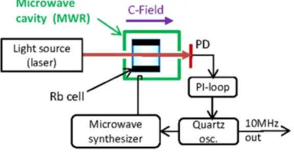
While most approaches to CSAC were based on the CPT scheme [2], the classical optical microwave double-resonance (DR) scheme [1], [4] was only rarely studied [5], [6]. For the miniaturization of DR Rubidium atomic clocks (see Fig. 1), the size reduction of the MWR to well below the wavelength of the atomic transition (6.835 GHz for 87
Rb) is one of the main challenges [7]. Solutions such as the magnetron-type MWR [8], miniature MWR using lumped LC elements [9], or slotted-tube MWR [10] were developed for Rb cells down to ∼1 cm size, but only very few microwave structures for mm-scale cells are reported, based on strip-lines or micro coupling
Fig. 1. Block scheme for a DR atomic clock (PD photo-detector).
loops [6]. In this paper we present a novel miniature MWR, the µ-LGR [11], for use with 36 mm3
micro-fabricated Rb cells [12]. The µ-LGR is composed of a multi-layer stack of planar loop-gap resonator structures [13] printed onto substrates, and coupled to a coaxial fed strip-line, with a total volume < 0.9 cm3
. The proposed solution meets the field requirements for DR atomic clocks (microwave magnetic field collinear to the laser beam) and the use of printed technology keeps the structure compact and suitable for low-cost batch fabrication using established techniques.
II. REQUIREMENTS
In order to sustain the microwave field to be applied to the atoms, the MWR has to be resonant with the ν0 = 6.835 GHz frequency of the 87
Rb |52
S1/2, Fg=1, mF=0>→ |52
S1/2, Fg=2, mF=0> clock transition, used as atomic ref-erence transition in Rb atomic clocks. The homogeneity of the microwave field inside the MWR in terms of intensity and orientation is essential to the performance of the atomic standard.
The magnetic part of the microwave field should have a magni-tude|B|'10−8Tesla, and should be parallel to the propagation direction of the light beam and to the direction of an applied static magnetic field (C-field, see Fig. 1). To characterize the magnetic field distribution, the Field Orientation Factor ξ (defined as in [7]) is used as figure of merit to evaluate the part of the magnetic field energy inside the Rb cell which is
Published in Proceedings of the IEEE-SENSORS-2012, paper 1435, 315-318, 2012 which should be used for any reference to this work
useful for the atomic clock signal. For the aimed application ξ ≥ 0.7 is required. The loaded Quality Factor (QL) of the microwave cavity should guarantee both a low power loss and a good coupling to the desired magnetic field mode. Design guideline values are QL'30, injected power Pin on the µW level and power loss Ploss'50 nW.
III. RESONATORDESCRIPTION
A. Principle of Operation
The Loop-Gap Resonator (LGR), also referred to as the split ring resonator [14] or slotted tube cavity [15], can be represented, in its simplest model, by an LC circuit where the loop is an inductor and the gap is a capacitor. The electric fields are supported by the gap with the magnetic fields surrounding the loop [16]. When the dimensions of the resonator are sensibly smaller than the half-wavelength of the resonant microwave frequency, the lumped element model can be used and the electric and magnetic fields can be considered separated.
In a first order approximation represented by eq. 1, the resonance frequency of the resonator is defined by the geometry of the electrode structure, including the radius (ro) and the thickness (W ) and the length (Z) of the electrodes, the width (t) and number (n) of gaps. Other versions of the formula, taking into account the fringing fields, the effect of the shield, and the limited length of the resonator can be found in [13], [16], [17]. C= εW Z nt , L= µ πr2 o Z −→ f = 1 2π√LC = 1 2π s n πr2 oεµ t W (1) A LGR can be coupled to external circuits both by capacitive or inductive means. In the first case a monopole probe is placed in proximity of the gap and it interacts with the gap’s fringe electric fields. In the latter case, an inductive loop can be used for coupling to the magnetic fields at either end of the resonator. In order to correct for inevitable manufacturing tolerances, fine tuning of the resonant frequency can be electronic [16] or mechanical [14], [18].
B. Model Validation
The proper operation for the µ-LGR was proven and opti-mized in several steps through software simulations, which were aimed to study the influence of relevant geometrical features, the presence of the Rb cell and of the cavity apertures. In particular, the influence of gap size (t) and width of electrodes (W ) were investigated in order to achieve the desired resonance frequency.
The simulation studies show that the resonance of the reflec-tion coefficient shifts to higher frequencies for higher values of t (as both L and C decrease), while the matching is also affected when t becomes too large. The influence of cavity apertures and dielectric properties of different materials on the resonance frequency and quality factor were also investigated in order to determine a suitable design for manufacturing. Finally, the influence of tuning screws was considered during
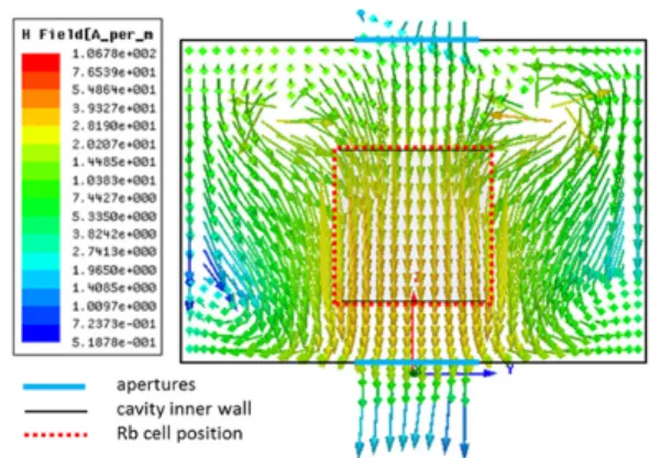
Fig. 2. Simulated magnetic field of the TE mode at 6.835GHz (t=2.0mm). The position of the micro-fabricated Rb vapor cell is indicated by the red dotted line.
Fig. 3. 3D view of the µ-LGR (left), diameter of the electrode stack is 11 mm. Fully assembled µ-LGR prototype with its outer shield (right).
the optimization of the electrodes structure, given their strong impact on both magnetic and electric fields. For t = 2.0 mm, the magnetic field at resonance has the desired TE mode distribution shown in Fig.2, with ξ= 0.9.
C. Resonator Design Characteristics
The µ-LGR is composed of a multi-layered structure of conductive electrodes separated by cylindrical dielectric layers, stacked along axial direction (z). These electrodes are two-dimensional structures, formed by patterns of metal film printed onto the dielectric layers. The dielectric material com-posing the resonator layers has a temperature-compensated dielectric constant in the microwave region.
The electrodes are planar realizations of loop gap resonators, juxtaposed in pairs in order to obtain a series of stacked loop-gap electrodes with 2 loop-gaps (n= 2) on each layer. The different layers of the electrode structure are electrically connected by means of metallized vias, but not in electrical contact with the outer metal enclosure.
Coupling of the microwave excitation to the µ-LGR is achieved by a loop-shaped strip-line, printed onto a separate layer of dielectric material. This excitation loop is placed above the µ-LGR electrode stack and is fed by a coaxial line. A cylindrical brass box encloses the multi-layer resonator structure, the coupling device and the Rb cell, to form an electrically conducting outer shield. This shield is in contact
6.4 6.6 6.8 7 7.2 7.4 x 10⁹ −45 −40 −35 −30 −25 −20 −15 −10 −5 0 Frequency [Hz] S11 [dB] tuned screws in screws out
Fig. 4. Tuning of the µ-LGR prototype (t=2.0 mm) at 6.835 GHz.
with the outer jacket of the coaxial line and is positioned relative to the other parts of the µ-LGR by means of dielectric spacing washer of appropriate size. The shield has apertures at its ends to allow for the laser beam to interact with the 87
Rb atomic vapor, which is held in a micro-fabricated cell [12] placed in the center of the µ-LGR.
Two screws mounted into the outer shield and protruding into the µ-LGR allow the fine tuning of the resonant frequency. The proposed technology allows for fully demounting the µ-LGR, in case the Rb cell or other parts of the resonator need to be removed or changed.
IV. PROTOTYPETESTRESULTS
Several prototypes of an optimized µ-LGR solution were built and successfully tested. In order to account for the influ-ence of the gap width on resonance frequency, the prototypes present different values of t (from 1.9 to 2.3 mm, with a step of 0.1 mm). The simulated model of the different prototypes (in terms of S11parameters) were compared to experimentally measured data obtained on the corresponding resonator pro-totypes. Results showed good agreement, yielding an average loaded quality factor QL of'26.
The two tuning screws were proven to be an efficient means to achieve the desired Rb resonance frequency at 6.835 GHz. The average tuning capability is 140 MHz for the built prototypes. The tuning of one prototype (t=2.0 mm) is shown in Fig. 4. The resonance frequency of the µ-LGR was measured as a function of temperature from 20°C (room temperature) to 100°C, showing an overall frequency shift of∼35 MHz over this temperature range, which can be corrected for by means of the tuning screws. The reflection coefficient remains≤-30 dB over this entire temperature range. In particular, the µ-LGR was found to operate according to requirements at the temperature of operation for an atomic clock of ∼80°C.
V. DR SPECTROSCOPYRESULTS
The µ-LGR was successfully used in a DR spectroscopy experiment, whose setup is sketched in Fig. 1. The DR spectroscopy consists in recording the transparency of the polarized Rb vapor, confined in the cell held inside the µ-LGR, while sweeping the frequency of the microwave field
Fig. 5. DR clock signal obtained with the µ-LGR, with 5.67 kHz linewidth at 9.9% contrast. across the 87 Rb clock transition (|52 S1/2, Fg=1, mF=0>→ |52 S1/2, Fg=2, mF=0>) [1], [4].
The polarization of the Rb vapor is established through optical pumping, and the residual light intensity after passing through the cell gives a measure of its transparency. The required light beam is provided by a frequency-stabilized laser head emitting at 780 nm (D2 line of Rb) [19], in which saturated-absorption spectroscopy on a dedicated87Rb cell [20] is used for frequency stabilization of the laser light. The µ-LGR is placed inside a coil generating the C-field, and mu-metal magnetic shields surround this setup in order to isolate the Rb atoms from external magnetic field fluctuations.
This setup allowed measuring excellent DR signals of the clock transition, with a contrast around 10% (see Fig. 5 for an example), which validates the suitability of the µ-LGR for clock applications. The excellent characteristics of this signal also underline the superior potential of the DR approach compared to CPT [5], in view of the obtainable short-term clock stability.
The obtained DR signals were used for stabilization of the quartz oscillator, when operating the setup of Fig. 1 as an atomic clock. First experimental results show measured clock stabilities (in terms of Allan deviation) of σy(τ ) = 7 × 10⁻¹²τ−1/2, see Fig. 6, which are in good agreement with the estimated signal-to-noise limit of σy(τ ) = 6.2 × 10⁻¹²τ−1/2 (calculated from the properties of the corresponding DR signal and the detection noise on the photo-detector) [21].
This result sets a new milestone for miniature atomic clock stabilities achieved with micro-fabricated cells, and proves the feasibility of the DR approach using the µ-LGR.
VI. CONCLUSION
We have presented a novel type of miniaturized microwave resonator for miniature atomic clock applications, the µ-LGR. The concept of the proposed device was validated and opti-mized through software simulations that were aimed to study the influence of relevant geometrical features, the presence of the Rb cell and of the cavity apertures.
Experimental results obtained on realized prototypes of the µ-LGR are in agreement with simulated results, showing that the prototypes could be easily tuned to the desired Rb resonance
Fig. 6. Clock fractional frequency instability obtained with the µ-LGR.
frequency of 6.835 GHz. Temperature-induced shifts of the resonator resonance frequency were measured and can be corrected for by using the tuning screws.
Using the µ-LGR, DR signals of the87Rb clock transition with excellent characteristics were observed. First clock stability measurements show a short-term clock stability of σy(τ ) = 7×10⁻¹²τ−1/2, which is better than other clocks using micro-fabricated Rb cells.
The presented results prove that the µ-LGR is suitable and of high interest for use in novel DR-based miniature atomic clocks.
ACKNOWLEDGMENT
This work was supported by the Swiss National Sci-ence Foundation, Sinergia grant CRSI20-122693. The authors would like to thank P. Scherler (UniNe- LTF) for experimental assistance, and Y. P´etremand (EPFL-SAMLAB) for manufac-turing the miniature Rb cell.
REFERENCES
[1] J. Camparo, “The rubidium atomic clock and basic research,” Physics
Today, pp. 33–39, Nov. 2007.
[2] S. Knappe, “MEMS atomic clocks,” in Comprehensive Microsystems. Elsevier B.V., 2008, vol. 3.
[3] SA.45s CSAC Chip Scale Atomic Clock datasheet, Symmetricom Inc., San Jose CA, USA, document DS/SA.45s CSAC/123010/pdf, 2010. [4] M. Pellaton, C. Affolderbach, Y. P´etremand, N. de Rooij, and G. Mileti,
“Study of laser-pumped double-resonance clock signals using a micro-fabricated cell,” Physica Scripta, vol. T149, 014013, 2012.
[5] R. Lutwak et al., “The chip-scale atomic clock - coherent population trapping vs. conventional interrogation,” Proc. 34th Annual Precise Time
and Time Interval (PTTI) Meeting, pp. 1–12, Dec. 2002.
[6] A. M. Braun et al., “RF-interrogated end-state chip-scale atomic clock,”
Proc. 39th Annual Precise Time and Time Interval (PTTI) Meeting, pp. 233–248, Nov. 2007.
[7] M. Violetti, C. Affolderbach, F. Merli, M. G. Z ¨urcher, and A. K. Skrivervik, “Miniaturized microwave cavity for rubidium atomic fre-quency standards,” in to be presented to European Microwave Week
(EuMW), Oct. 28–Nov. 2 Amsterdam RAI, The Netherlands, 2012. [8] H. Schweda, G. Busca, and P. Rochat, “Atomic frequency standard,”
European patent EP 0561261, 1997.
[9] J. Deng, “Subminiature microwave cavity for atomic frequency stan-dards,” Proc. of IEEE International Frequency Control Symposium and
PDA Exhibition, pp. 85–88, 2001.
[10] B. Xia, S. Zhong, D. An, and G. Mei, “Characteristics of a novel kind of miniature cell cavity assembly for rubidium frequency standards,” IEEE
Trans. on Instrum. and Measurement, vol. 55, pp. 1000–1005, 2006.
[11] M. Violetti, C. Afforderbach, F. Merli, G. Mileti, and A. K. Skrivervik, “Microwave resonator, quantum sensor, and atomic clock,” European
Patent Application No. 12155696, February 16, 2012.
[12] Y. P´etremand, C. Affolderbach, R. Straessle, M. Pellaton, D. Briand, G. Mileti, and N. F. De Rooij, “Microfabricated rubidium vapour cell with a thick glass core for small-scale atomic clock applications,” J.
Micromech. Microeng., vol. 22(2), 025013, 2012.
[13] W. Froncisz and J. S. Hyde, “The loop-gap resonator: a new microwave lumped circuit ESR sample structure,” J. Magn. Reson., vol. 47, pp. 515–521, 1982.
[14] W. N. Hardy and L. A. Whitehead, “Split ring resonator for use in magnetic resonance from 200-2000MHz,” Rev. Sci. Instrum., vol. 52(2), pp. 213–216, 1981.
[15] T. Sphicopoulos and F. Gardiol, “Slotted tube cavity: a compact res-onator with empty core,” IEE Proceedings, vol. 134, no. 5, pp. 405–410, 1987.
[16] M. Mehdizadeh, T. Ishii, J. Hyde, and W. Froncisz, “Loop-gap resonator: a lumped mode midrowave resonant structure,” IEEE Trans. Microw.
Theory Tech., vol. 31, pp. 1059–1064, 1983.
[17] M. Mehdizadeh and T. Ishii, “Electromagnetic field analysis and calcu-lation of the resonance characteristics of the loop-gap resonator,” IEEE
Trans. Microw. Theory Tech., vol. 37, pp. 1113–1118, 1989.
[18] G. Mei, D. Zhong, S. An, J. Liu, and X. Huang, “Miniaturized microwave cavity for atomic frequency standard,” US Patent 6,225,870
B1, May 1, 2001.
[19] C. Affolderbach and G. Mileti, “A compact laser head with high-frequency stability for rb atomic clocks and optical instrumentation,”
Rev. Sci. Instrum., vol. 76, no. 7, p. 073108, 2005.
[20] D. W. Preston, “Doppler-free saturated absorption: Laser spectroscopy,”
Am. J. Phys., vol. 64, no. 11, pp. 1432–1436, 1996.
[21] T. Bandi, M. Pellaton, D. Miletic, C. Affolderbach, F. Gruet, R. Matthey, G. Mileti, C. Stefanucci, M. Violetti, F. Merli, J.-F. Z ¨urcher, and A. K. Skrivervik, “Double resonance in alkali vapor cells for high performance and miniature atomic clocks,” in Proc. IEEE International Frequency
Control Symposium, IFCS, May 21–24, Baltimore, MD, USA 2012.