PERFORMANCE OF A BUSY-TONE APPROACH ON 802.11 WIRELESS NETWORKS
A THESIS
PRESENTED TO THE UNIVERSITY OF QUEBEC IN CHICOUTIMI IN PARTIAL FULFILLMENT OF REQUIREMENTS
FOR THE DEGREE OF MAS TER IN ENG INEERING
BY FIRAS HIJAZI
Mise en garde
La bibliothèque du Cégep de l’Témiscamingue et de l’Université du Québec en Abitibi-Témiscamingue a obtenu l’autorisation de l’auteur de ce document afin de diffuser, dans un but non lucratif, une copie de son œuvre dans Depositum, site d’archives numériques, gratuit et accessible à tous.
L’auteur conserve néanmoins ses droits de propriété intellectuelle, dont son droit d’auteur, sur cette œuvre. Il est donc interdit de reproduire ou de publier en totalité ou en partie ce document sans l’autorisation de l’auteur.
Warning
The library of the Cégep de l’Témiscamingue and the Université du Québec en Abitibi-Témiscamingue obtained the permission of the author to use a copy of this document for non-profit purposes in order to put it in the open archives Depositum, which is free and accessible to all.
The author retains ownership of the copyright on this document. Neither the whole document, nor substantial extracts from it, may be printed or otherwise reproduced without the author's permission.
UNIVERSITE DU QUEBEC EN ABITIBI-TEMISCAMINGUE
PERFORMANCE DEL' APPROCHE BUSY-TONE SUR LES RESEAUX SANS FILS 802.
MÉMOIRE
PRÉSENTÉ À L'UNIVERSITÉ DU QUÉBEC À CHICOUTIMI COMME EXIGENCE PARTIELLE
DE LA MAÎTRISE EN INGÉNIERIE
PAR
FIRAS HIJAZIAcknow ledgmen ts
The first lines of this thesis go to express my gratitude and appreciation to all the people who helped me accomplish this work, which took place in the laboratory of research (LRTCS) in Val d'Or, Quebec.
Foremost, 1 would like to express my smcere gratitude to my advisor Professor Nadir Hakem for the continuous support of my Master studies and researches, for his motivation, patience, enthusiasm, and immense knowledge. His guidance helped me m all the time of research and writing of this thesis. Besicles my advisor, 1 would like to thank my co-director Professor Nahi Kandil for guiding my research for the past two years with his knowledge and experience and
continuous support.
Also, 1 want to thank my fellow colleagues for the stimulating discussions, for their help at all levels, for the moral support and most importantly for making our laboratories a better place to work and providing the right atmosphere to do researches, also for the fun that we had these past two years .
Last but not the least; 1 would like to thank my family, my parents and my two brothers for supporting me spiritually throughout my life and especially through my studies. For that 1 dedicate my work to them.
Contents
Acknowledgments ... ii
List of figures ... vii
Abstract ... ix Résumé ... x Glossary of Abbreviations ... xi Chapter 1 Introduction ... 1 1.1 Introduction ... 1 1.2 Research objectives ... 2
1.3 Structure of the thesis ... 2
Chapter 2 The 60 GHz frequency band ... ... 5
2.1l\.1mWave Wireless TechnologyOverview ... S 2.2 Challenges and properties of the 60 GHz ch annel.. ... 6
2.3 Advantages of 60 GHz ... 7
2.4 Potential applications ... 8
2. 5 Adapted 60 GHz MAC protocol ... 9
Ch apter 3 MAC protocol Ch allenges ... ... .. ... .. .... ... .. ... 10
3.1 Introduction ... 10
3.2 The H idden-Terminal problem ... 12
3.3 The Exposed Terminal problem ... 14
3.4 The Deafness problem ... 16
Ch apter 4 MAC protocols overview ... ... ... ... 18
4.1 Introduction ... 18
4.2 The data link layer ... 18
4.4 :rvfAC protocols goals ... 19 4.5 Conventional :rvfAC protocols ... 20 4.5.1 Contention-free protocols 000000000000000000000000000000000000000000000000000000000000000000000000000000000000021
4.5.1.1 Time Division Multiple Access (TDMA) oooooooooooooooooo oooo oooooooooooooooooooo oooo oooooooo21 4. 5.1.2 Frequency Division Multiple Access (FD:rvfA) 000000 0000 ... 0000 000000 000000 00 ... 0000 00.22 4.5.1.3 Code Division Multiple Access (CD:rvfA)oooooooooooooooooooooooooooooooooooooooooooooooooooooo23 4.5.2 Contention-based protocols.oo.oooooooooooooooooooooo ooooooooooooooooooooooo oo oooooooooooooooooooooo ooooooooo.23 4.5.3 Contention-based protocols types oooooooooooooooooooooooooooooooooooooooooooooooooooooooooooooooooooooooo.24 4.5.3.1 Aloha ... 24 4. 5.3 .2 Carrier Sense Multiple Access (CSMA) 0000 000000 000000 000000 00 0000 000000 000000 000000 00 0000 000025 4.5.3.3 CSMA/CD (CSMA with collision detection) ooooooooooooooooooooooooooooooooooooooooooooooo.27 4.5. 3.4 CSMA/CA (CS:rvfA with collision avo idance) or Media Access with Collision Avoidance (:rvfACA) 00000000000000000000000000000000000000000000000000000000000000000000000000000000000 28 4. 5. 3.6 :rvfACA for wireless networks (MACA W) 00 000000 000000 oooo ooo oooo 000000 000000 oooo oooo oooo 0000 29 4. 5. 3. 7 Busy Tone Multiple Access (BT:rvfA) 00 000000 000000 000000 0000 00 00 0000 000000 000000 0000 00 00 0000 0000 29 4.5. 3.8 Dual Busy Tone Mu ltiple Access (DBT:rvfA) 000000000000000000000000000000000000000000000000 30 4.5.4 Hybrid Protocols oooooooooooooo ooo oooooooooooooooooooooo ooo ooooooooooooooooooooo ooo ooooooooooooooooooooo oooooooooo. 30 4. 5.4.1 Distributed Packet Reservation Mu ltiple Access Protocol (D-PR:rvfA) 000000 00. 31 4.5.4.2 Collision Avoidance Time Allocation Protocol (CATA) 000000000000000000000000000000 31 4. 5.4.3 HOP Reservation Multiple Access Protocol (HR:rvfA) 000000 000000 000000 oooo oooo oooo 0000 32 4. 6 :rvfAC protocol 802.11 ... 32
4. 7 Protocols for 60 Gl-Iz ... 00 ... ... 00 ... ... 00 ... ... 00 ... 33
Ch apter 5 Proposed method ... 35 5.1 Introduction ... ... ... ... ... 35 5. 2 The Proposed :rvfAC Algorithm .... oo .... oo .... oo .. ... oo ... oo .... oo .. ... oo .... oo .... oo .... oo .... oo .... 35
5.3 The standard 802.11 ad ... 39
5.4 The combination between 2.4 GHz and 60 GHz ... ... ... .41
Chapter 6 ... 43
6.1 Introduction ... 43
6.2 OPNET Modeler ... ... ... ... ... .43
6.2.1 The Node Model ... ... ... ... ... .44
6.2.2 Directional Antenna ... 46
6.2.2.1 Antenna module ... 46
6.2.2.2 Antenna pattern ... ... ... ... ... 47
6.2.3 The Pro cess Mo del. ... 48
6.2.3.1 The Process Model Editor. ... .49
6.2.3.2 State connections - Transitions ... ... ... ... 50
6. 3 The Network M odel ... 51
6.3.1 Simulation param eters ... ... ... ... ... 52
6.4 Simulation results ... 54
6.4.1 Performance of the network throu ghput .... .... ... .... ... .... ... 55
6.4.2 Performance of the packet retransmission 00oooooo .... oo .... oo ... oo .... oo .... oo ... oo. 56 6.4.3 Performance of the network delay .. oo .... oo .. ... oo .... oo .... oo .. oo .. ... oo .... oo .... oo .... ... oo .... 57
6. 5 Con clusion ... 58
Ch apter 7 Conclusion and perspectives .. oo ... ... oo ... ... oo ... ... oo .... 59
7.1 Conclusion 00 .... 00 .... 00 .... 00 .... 00 .... 00 .... 00 .... 00 .... 00 .... 00 .... 00 ... 00 .... 00 .... 00 .... 00 .... 00 .... 00 .... 00 .... 00 ... 59
7. 2 Perspectives ... 59
List of figures
Figure 2-1 Available spectrum in 60GHz band for indoor wireless communication around
the world ... 5
Figure 3-1: The Hidden-Terminal problem ... 13
Figure 3-2: CTS collision ... 14
Figure 3-3: The Exposed Terminal Problem ... 15
Figure 3-4: The Deafness problem ... 16
Figure 4-1: MAC protocols classification ... 21
Figure 4-2: In pure ALOHA, frames are transmitted at completely arbitrary times ... 25
Figure 4-3: Comparison of the channel utilization versus load for various random access protocols [5] ... 27
Figure 4-4: CSMA/CD can be in one ofthree states: contention, transmission, or idle ... 28
Figure 4-5: CSMA/CA ... 28
Figure 5-1: The proposed algorithm Float Chart ... 38
Figure 5-2: Coordination between 2.4 GHz and 60 GHz ... 42
Figure 6-1: Node Model. ... 45
Figure 6-2: Antenna Pattern in 3D viewer ... 4 7 Figure 6-3: Antenna Pattern polar plots ... 48
Figure 6-4: Polar, Azimuth coordinate system used to represent Antenna Patterns ... 48
Figure 6-5: The different types of states ... 49
Figure 6-6: Pseudo-Code equivalent of multiple transitions ... 50
Figure 6-7: Process Model in OPNET Modeler ... 51
Figure 6-8: Wireless LAN Throughput ... 55
Figure 6-9: Packets retransmission ... 56
List of tables
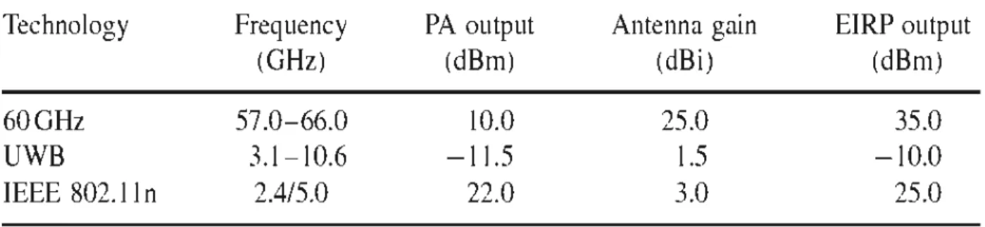
Table 2.1: Comparison of the typical implementation of 60 GHz, UWB and 802.lln
systems in terms of their output power, antenna gain and EIRP output.. ... 6
Table 2.2: Transmission lost at 60 GHz and 2.5 ... ... ... 7
Table 3.1: WLAN parameters for 5 GHz and 60 GHz ... ... ... 11
Abstract
The big evolution of modem applications in the wireless networks domain as the wireless videos remote access, big files transfer, streaming and downloading high definition videos etc, has led to using the mmWave technology (60 GHz for example) that represents an important solution for the se applications because of the advantages presented by this frequency band such as the high data rate transmission up to multi gigabits, also the large bandwidth that goes up to 7 GHz.
The use of the mm Wave technology requires a MAC protocol which ensures the channel sharing between users in a multi-node network, with directional antennas that increase spatial reuse and cover a wider area compared to the omnidirecti on al antennas.
Many access method approaches were used in order to resolve these problems, for instance, the methods that use a signaling channel, then methods that exploit directional antennas with directional frame s, and those using beacons and many others ....
In our project, we worked on the adaptation of the 'Busy - Tone' method using the 802.11 ad protocol with directional antennas in addition to a coordination between 2.4 GHz and 60 GHz.
This method offers a big solution to resolve the collisions of data and control packets that affect and reduce the network capacity and lead to data loss.
Simulation results showed the efficiency of this model by reducing collisions caused by hidden terminais, therefore, enhancing the performance of the network in terms oftransmission delay, retransmission attempts and throughput.
Résumé
L'évolution des applications modernes dans le domaine des réseaux sans fils tel que 1 'accès à distance des vidéos sans fils, le transfert des gros fichiers, flux des vidéos à haute définition etc .... nécessite 1 'utilisation de la bande 60 GHz qui présente une solution très importante pour ces applications grâce aux avantages que présente cette bande tel que le taux de transmission des données qui atteint quelques Gigabits, et aussi grâce à la bande passante du canal qui est environ 7 GHz.
L'utilisation de cette bande de fréquence nécessite un protocole MAC qui assure le partage de canal entre les utilisateurs dans un réseau multi-nœuds. Ce protocole doit tenir compte les problèmes et les défis qui se produisent grâce à l'utilisation de la bande 60 GHz, tel que les problèmes des terminales cachées et exposées
Dans ce projet on a proposé une méthode qui se base sur l 'adaptation de protocole 802.llad avec la méthode 'Busy-Tone 'parce qu'elle représente la solution la plus efficace pour résoudre les problèmes des collisions des paquets de donnés et les paquets de contrôle qui sont causés normalement par la présence des terminales cachées et exposées.
L'approche proposée consiste aussi à utiliser les antennes directives qm augmentent la réutilisation spatiale et couvre une portée plus grande par rapport à l'antenne omnidirectionnelle. Ces antennes ont été utilisés à côté des antennes omnidirectionnelles avec une coordination entre les deux, alors les antennes omnidirectionnelles sont utilisées pour envoyer les signaux 'Busy-Tone ' tandis que les antennes directives sont utilisées pour envoyer les paquets de données.
Les résultats de la simulation ont montré une amélioration au niveau de la performance du réseau en terme du débit, du délai et les essaies de retransmission en comparant avec le standard 801.11ad.
MAC HD EIRP Wlans Wpans UWB LOS NLOS OSI LLC DCF HCCA TDMA CDMA FDMA WiMAX QoS RF PN CBP CSMA CS MA/CD CS MA/CA MACA MACAW CTS RTS
Glossary of Abbreviations
Medium Access Control High definition
Effective isotropie radiated power Wireless local area networks W ireless personal are a networks Ultra wide band
Line of Sight None Line of sight
Open Systems Interconnect Logical Link Control
Distributed coordination function HCF controlled channel access Time Division Multiple Access Code Division Multiple Access Frequency Division Multiple Access
Worldwide Interoperability for Microwave Access Quality of services
Radio frequency Pseudorandom noise Contention-based protocol Carrier Sense Multiple Access CSMA with collision detection CSMA with collision avoidance
Media Ac cess with Collision A voidance MACA for wireless networks
Clear to send Ready to send
ACK BTMA DB TMA CATA HRMA SRMA/PA RTMAC WIGIG GHz Acknowledgment
Busy tone multiple access Dual Busy Tone Multiple Access
Collision Avoidance Time Allocation Protocol HOP Reservation Multiple Access Protocol
Soft Reservation Multiple Access with Priority Assignments Real-Time Medium Access Control
W ireless Gigabit Alliance Gigahertz
1.1 Introduction
The mm Wave technology opens the do or on a big variety of potential applications that requires a large bandwidth as presented in the 60 GHz frequency band. Due to its huge unlicensed bandwidth (up to 7 GHz). Many new applications that require high data rate can be easily supported, such as Wireless HD, single and multi set uncompressed video streaming, office desktop data transfers, conference adhoc data transfer, and Kiosk file downloading.
Another factor that makes this technology so attractive is that 60 GH regulation allows much higher effective isotropie radiated power (EIRP) compared to other existing wireless local and personal networks (Wlans and Wpans). High EIRP is required to overcome the high path loss in the 60 GHz band.
On the other hand, using this physical layer demands an adaptation of the Medium Access Control (MAC) layer that respects its characteristics and properties and also enhances its performance. Furthermore, the main objective of Multiple Access Control (MAC) protocols is to schedule access of multiple competing nodes in communication networks to a shared channel.
This control has a role of preventing interference between the nodes in a multi-hop network and packets collisions which lead to data loss and bandwidth waste. One of the main reasons of packets collisions is the problem of hidden terminais. This problem occurs often in multi-hop networks where sorne terminais are
considered "Hidden" from each other ( either because they are out of sight or out of range).
1.2 Research objectives
The main objective of our research is to adapt a MAC protocol that overcomes the problems mentioned above; the most important problems in our research are the hidden and exposed terminais. Those problems occur a lot in multi-hop networks causing packets collisions and data loss which reduce the capacity and the performance ofthe network.
The MAC protocol used in this work is the 802.11 ad, this protocol is made for mm Wave technology and it was derived from the standard 802.11 proto col for wireless LANs. In addition to 802.11ad, we used the 'Busy-Tone' method and directional antennas.
So this research was clone in order to:
- Reduce the problem of hidden terminais.
- Increase the capacity and the throughput ofthe network. - Decrease the collisions of data and control packets.
- Coordinate the use of directional and omnidirectional antennas. - Guarantee a better medium access and control.
1.3 Structure of the thesis
This thesis is organized as follows:
In the first chapter we did a general introduction to the 60 GHz frequency and the MAC protocol; also in the chapter we defined our research objectives and the structure of this thesis.
The next chapter presents a mmWave wireless technology overview, the 60 GHz frequency in specifie and its available spectrum for indoor wireless communications around the world and the reasons that makes this technology very attractive for modem applications, then we present the challenges and the properties of this channel and most importantly the benefits presented by this frequency band in wireless communications.
In chapter three we present our problematic, the main issue that we are working to solve which the collision problem is caused by hidden terminais and deafness, also we presented the problem of exposed terminais and how these problems affect the network performances in many aspects such as the throughput, transmission delay and retransmission attempts.
Chapter four presents a MAC protocol overview, it includes detailed explications about the data link layer, the medium access control sub layer and its role, then we explained what is a MAC protocol and its goals, also in this chapter you will find a detailed study about protocol MAC classification, the different t ypes and the role of each one. Also we give an overview on the related works and the methods that have been proposed so far to deal with the same issues and what are the advantages and disadvantages of each method.
The following chapter presents the proposed method, in other words the idea that we proposed to solve the problem listed in chapter three. This method is based on the adaptation of the standard 802.llad to be used with 'Busy-Tone ' method in addition to the use of directional antennas in coordination w ith omnidirectional antennas.
In chapter six we present the modeling phase, or the model that we used and implemented using the software OPNET, the use of this software was based on the
given results which are considered more realistic compared to other software such as network simulator. In this chapter we present the different phases and methods that were used to achieve our goal which creating a functional model to test our idea which will be shown in the simulation results and the interpretation. In the second part of this chapter we present the network model that we used in addition to the simulation parameters, then we show the simulation results and the interpretation of these results to show the efficiency of our proposed method and ho it affects the performance ofthe network
Finally in chapter seven, we gtve our conclusion and comments about the proposed method based on the simulations results, and how the method affected the network performance, then we talk about the perspective and possible future work based on the method we proposed such as using a dual busy t one method or exploits the use of directional antennas .
Chapter 2
The 60 GHz frequency band
2.1 MmWave Wireless Technology Overview
The need for very high data rate radio communications applications (1 Gbit/s or higher) makes the mmWave technology one of the most promising forms for multi-gigabit wireless communications for wireless networks due to its huge unlicensed bandwidth (up to 7 GHz). This huge bandwidth represents great potential in terms of capacity and flexibility, making 60 GHz technology very attractive for gigabit wireless applications. The fact that this band is unlicensed and largely harmonized across most regulatory regions in the world is a big advantage, in contrast to the meager spectrum available in the lower frequency bands for existing technologies such as Wi-Fi.
57 58 ~ GO &1 62 63 S4 65 66
Ausb'ali.l p.SGHz) 159.4 62~
Canada & USA t7GittJ
bz
~
Jap.1n (7GHz)
ll9
IG IE11~ (i;Hz)
Figure 2-1 Available spectrum in 60GHz band for indoor wireless communication around the world
Another factor that m akes this technology so attractive is that 60 GHz regulation allows much higher effective isotropie radiated power (EIRP) compared to other existing w ireless local and personal networks (Wlans and Wpans). Table 1 shows
examples of typical 60 GHz, UWB and IEEE 802.11systems that operate near the US Federal Communications Commission (FCC) regulatory limit [2].
Table 2.1 Comparison of the typical implementation of 60 GHz, UWB and 802.11 n systems in terms oftheir output power, antenna gain and EIRP output
Technology
Frequency
PA output
Antenna gain
EIRP output
60GHz
UWB
IEEE 802.lln
(GHz)
57.0- 66.0
3.1-10.6
2.4/5.0
(dB rn)
10.0
- 11.5
22.0
2.2 Challenges and properties of the 60 GHz channel
(dBi)
25.0
1.5
3.0
First, the propagation of the 60 GHz band is characterized by high levels of oxygen absorption and rain attenuation limiting the range of communication systems using this band; but it also offers interference and security advantages when compared to other wireless technologies.
Small bearn sizes coupled with oxygen absorption makes these links highly immune to interference from other 60GHz radios, so two links with slightly different paths will not interfere, while oxygen absorption ensures that the signal does not extend far beyond the intended target, even with radios along the exact same trajectory. Hence, it will allow a high lev el of frequency re-use, and therefore, makes it attractive for a variety of short-range communication applications.
Secondly, 60GHz channel generally exhibits quasi-optical properties, meaning the strongest components tend to be Line of Sight (LOS). Non Line of Sight (NLOS) components do exist, but mostly in the form of reflection. 60 GHz
(dB rn)
35.0
- 10.0
25.0
band measurements [3] show that in general, the strongest reflected components are at !east 10 dB belowthe line ofsight (LOS) component.
Thirdly, one of the major challenges when using 60 GHz frequency band is the path loss factor. For example, the propagation loss of 60 GHz signais in :free space is 22 dB higher than th at of 5 GHz signais [4], also the signal at this frequency is very sensitive to obstacles, (e.g. human bodies, walls ,objects ... ),table 2.2 gives an idea about the transmission !ost at 60 GHz and 2.5 GHz for different obstacles.
Table 2.2: Transmission loss at 60 GHz and 2.5 in dB
Thickness (cm)
60GHz 2.5 GHz
drywall
2.5
6.0
5.4
Office
1.9
9.6
0.5
whiteboard
Clear glass
0.3
3.6
6.4
Mesh glass
0.3
10.2
7.7
Clutter
-
1.2
2.5
2.3 Advantages of 60 GHz
The 60 GHz :frequency band off ers a lot of benefits and has its great advantages in wireless communications.
1- Unlicensed operation, there is no need to spend lots of money and time to obtain a li cense from a telecom regulator.
2- One of the greatest advantages is the large bandwidth as mentioned above, this bandwidth can go up to 7 GHz comparing to <0.3 GHz in other
unlicensed bands, allowing and presenting many modem applications that need such a bandwidth.
3- Highly secure and virtually interference operation; it is a result from short range transmissions due to oxygen absorption, narrow antenna bearn width and limited use of 60 GHz spectrum.
4- Carrier-class communication links enabled, 60 GHz can be engineered to deliver ''five nines" of availability if desired.
5- Channel access in 60 GHz will use directional communications, which will lead to exploit spatial reuse in 60 GHz and increase the spectrum efficiency.
2.4 Potential applications
With the 7 GHz bandwidth allocated in most countries, the 60 GHz frequency band has become the technology enabler for many gigabits transmissions applications that are constrained at lower frequencies. Many indoor applications are presented such as:
1- Uncompressed high definition (HD) video streaming that enables users to wirelessly display content to a remote screen with wired equivalent quality/experience.
2- ' Synch and go' file transfer that enables gigabytes of file transfer in a few seconds.
3- Wireless docking stations that allow multiple peripherals (including an extemal monitor) to be connected without the need for frequent plugging and unplugging.
4- Wireless gigabit Ethemet that permits bidirectional multi-gigabit Ethemet traffic.
5- Vehicular applications which are partitioned into three classes: intra-vehicle wireless networks, inter-vehicle wireless networks and vehicular radar.
6- LAN-to-LAN connections (LAN bridges), buildings m a campus environment can be connected together with wireless links that offer high bandwidth, excellent data security availability.
2.5 Adapted 60 GHz MAC protocol
Working at the 60 GHz frequency band require a modified MAC protocol to serve its characteristics, and to overcome all the challenges in order to present a better quality of service which lead to a better network performance. In the following chapter, we explain what is a protocol MAC and what are his functionalities and also what types of protocols exist.
Chapter 3
MAC protocol Challenges
3.1 Introduction
As we mentioned previously, using the 60 GHz frequency band requires a special adapted MAC protocol to serve its characteristics and respect its properties. So many challenges that we can find in the MAC layer when working with mm Waves like the robustness of the link, because of the high attenuation by obstructions, hence, the 60 GHz link is much more likely to break in comparison with 2.4 or 5 GHz. Therefore, it is important to design a MAC protocol that can handle link failures efficiently.
Another challenge in 60 GHz MACis that it must support a high number of directions relative to the number of associated deviees. Most, or all, directional MAC protocols proposed for 2.4 1 5 GHz are concentrated on the support of eight independent directions to each deviee. However, creating a standard for the mm Wave technology requires the support of 32 (and in sorne cases 64) in dependent directions so that a higher gain antenna can be obtained.
Supporting a high number of directions represents big challenges for the protocol; the most important one among them is probably the use of omnidirectional transmissions, so the communication becomes extremely expensive as the throughput should fall roughly proportionally to the number of supported directions.
Therefore, the design of the MAC needs to m1mm1ze the use of omnidirectional transmissions at low rates and exploit the high rate directional communication, not only for data transmission but also for control functions and management.
Another major challenge is the requirement of an effective mechanism of a contention-based random access method. The following table shows a comparison between WLAN parameters for 5 and 60 GHz.
Table 3.1 shows the different parameters used in both 5GHz and 60 GHz frequencies where:
EIRP (equivalent isotropically radiated power) represents the amount of power that a theoretical isotropie antenna (which evenly distributes power in all directions) would emit to pro duce the peak power density observed in the direction of maximum antenna gain. EIRP can take into account the losses in transmission line and connectors and includes the gain of the antenna. The EIRP is often stated in terms of decibels over a reference power emitted by an isotropie radiator with equivalent signal strength.
Eb/No or (SNR: signal to n01se ratio), it is especially useful when companng the bit error rate (BER) performance of different digital modulation schemes without taking bandwidth into account. The penetration loss indicates the fading of radio signais from an indoor terminal to a base station due to obstruction by a building.
Beamforming represents a signal processing technique used m sensor arrays for directional signal transmission or reception. This is achieved by combining elements in a phased array in such a way that signais at particular angles expenence constructive interference while others experience destructive interference
Table 3.1 : WLAN parameters for 5 GHz and 60 GHz
umber of antennas
Maximum ElRP (FC )
Transmit
pû\ltr/antenna
(P,)
Transmit beamfonning gain
(G,)
Power combining gain
(G")
Receive beamfonning gain (G,)
Modulation coding scheme
Minimum tiNo@ IOe-5
Aperture Joss
@
1
m
Penetration loss/drywall
(L.,)
Penetration losslperson (L,)
3.2 The Hidden-Terminal problem
5GHz
4
30dBm
+
6dBi (antenna gain)
24dBm
0
0
0
64QAM
516
19dB
-48dB
4 7dB[I2]
5dB( 15j
60GHz
36
40dBm
4dBm
ISdB
lSdB
lSdB
BPSK 3/4
lOdB
-68dB
8 8d8(13]
14.5dB(l4]
Recently, research interest in the performance analysis of wireless networks was revived. An issue of utmost importance in this class of networks, classified as one of the severest reasons for the degradation of their performance, is the hidden terminal problem.
Nodes usually work in a half-duplex mode in wireless ad hoc networks and cannot transmit and receive at the same time. Hence, nodes are not able to detect collisions during transmissions. When a collision occurs, the source node continues transmitting the complete packet. When the packet is large, the radio resources are wasted greatly due to the corrupted packets.
In a multi-hop environment, collisions are much more serious than those in a single-hop environment due to the existence of hidden terminais; therefore, degrade the network throughput significantly [12].
Hidden terminais in a wireless network refer to nodes that are out of range of other nodes or a collection of nodes. To exp lain this problem in a more detailed way see figure 3-1.
A wants to send to B but cannot haar that
Bis busy
Figure 3-1: The Hidden-Terminal problem
Since not all stations are within radio range of each other, transmissions going on in one part of a cell may not be received elsewhere in the same cell. In this example, station C is transmitting to station B. If A senses the channel, it will not
hear anything and falsely conclude that it may now start transmitting to B.
To address the collisions caused by this problem, many solutions have been proposed. The first and simplest solution was the RTS/CTS (Ready to Send 1 Clear to Send) method, this handshake between the transmitter and the receiver has a role in preventing data collisions by reserving the channel before transmitting. However, this solution was not a complete solution because RTS /CTS packets themselves are subject to collisions as figure 3-2 shows.
RTS I RTS2
~
~."··:.Cl
,Q7=01-.-c_r_s_'-t:CJ:=
~
.,._._ __
cT_s_z_~,Cf?So'
S I RI R Rl S2
Figure 3-2: CTS collision
When the traffic load is heavy, DATA packets may still experience collisions with a high probability due to the loss of RTS or CTS packets [13]. In order to overcome this problem the 'Busy-Tone' method was introduced, this solution was proposed to protect the data packets as well as the control packets (RTS/CTS) and prevent their collisions.
3.3 The Exposed Terminal problem
RTS/CTS handshake mechanism was introduced to wireless MAC layers to eliminate the hidden terminal problem. However, this mechanism introduces a new problem termed the exposed terminal problem [14]. In wireless networks, the exposed node problem occurs when a node is prevented from sending packets to other nodes due to a neighboring transmitter. To understand this issue see figure 3-3.
S wa nts to send to C but mistakanly lhillks the 1ransmtss.ion "' 1 fail
c
Figure 3-3: The Exposed Terminal Problem
Here B wants to send to C so it listens to the channel. When it hears a
transmission, it falsely concludes that it may not send to C, even though A may be transmitting to D (not shown). In addition, most radios are half duplex, meaning that they cannot transmit and listen for noise bursts at the same time on a single frequency [ 5].
The RTS/CTS mechanism can help solving this issue only if the terminais are synchronized and packet sizes and data rate are the same for both transmitting terminais. When a node hears an RTS from its neighbor, but not the corresponding CTS, that node can deduce that it is an exposed node and is permitted to transmit to other neighboring nodes.
If the nodes are not synchronized (or if the packet sizes are different or the data rates are different) the problem may occur that the sender will not hear the CTS or the ACK during the transmission of data of the second sender.
The major effects of the exposed terminal problem are the underutilization of the channel and the low effective throughput.
3.4 The Deafness problem
This problem is basically created when using directional antennas, a node using a directional antenna is considered deaf in all the directions except for the directions in its main bearn [15]. Figure 3-4 shows a simple example ofthe deafness.
1 1 1
c•
1 ' 1 / RTSFigure 3-4: The Deafness problem.
To understand more this problem, we consider that there is a communication between nodes A and B with the main bearn of A is pointed toward B; node C cannot
hear the ongoing communication between those two nodes so it attempts to transmit packets to A by sending out aRTS. Since the main lobe of node ' s A antenna is not in
direction of Node C, it does not hear RTS packets sent by C, which results in timeouts in Node C. Furthermore, the deafness problem can start a chain effect throughout the network and cause low performance, unfairness, and deadlock.
Deafness does not only affect the MAC layer, but also the performance of higher layers. For example, when a node send aRTS packet and does not receive its CTS, it backoffs and tries to send its R TS another time. This leads to excessive wastage of network capacity in control packet transmission. Larger backoff intervals also result into unfairness wherein a flow completely captures the wireless shared medium [16].
The impact of this problem is also severe on the routing layer because each consecutive unsuccessful transmission of a packet (R TS or DATA) at the MAC causes the increment of a variable called Short Retry Limit (SRL) which results in considerable network performance degradation, as route request packets are often flooded [ 16].
Finally, deafness may also impact the performance of the transport layer. Deafness may preclude a node from receiving a TCP ACK, for example. Clearly, this negatively impacts TCP performance as it may continuously enter its congestion control mechanisms [16].
The deafness problem can be solved by sending the RTS and CTS omm-directionally, while the data packets are sent via directional antennas. However, this solution has its disadvantages the R TS and CTS packets can coll ide which willlead to more data loss while comparing to busy tone, the signal is sent for one time and it keeps the channel busy as long as the data transmission procedure is taking place [17].
Chapter 4
MAC protocols overview
4.1 Introduction
This chapter presents a MAC protocol overview, it includes detailed explications about the data link layer, the medium access control sub layer and its role, then we explained what is a MAC protocol and its goals, also in this chapter you will find a detailed study about protocol MAC classification, the different types and the role of each one. Also we give an overview on the related works and the methods that have been proposed so far to deal with the same issues and what are the advantages and disadvantages of each method.
4.2 The data link layer
It is the second layer in the Open Systems Interconnect (OSI), this layer provide data transmission control, it handles the moving of data in and out across the physical layer in a network. It also ensures that incoming data has been received successfully by analyzing bit patterns at special places in the frames.
The data link layer has many specifie functions [5]:
• It provides a well-defined interface to the network layer.
• It deals with transmission errors.
• It regulates the flow of data so that slow receivers are not swamped by fast senders.
This layer is divided into two sublayers: the Medium Access Control (MAC) and the Logical Link Control (LLC).
4.3 The Medium Access Control sub layer
This layer contains all the protocols that are used to determine who uses next a multi-access channel. The main function of this layer is to regulate the use of the medium through a channel access mechanism, this mechanism presents a way to divide the main channel between nodes, and this operation of channel sharing is controlled by the MAC protocol, it tells each node when to transmit its packets and when it is expected to receive packets.
The main objective ofthe MAC protocol algorithm is to ensure a secure data transmission, and to prevent collisions that happen occasionally in the network for many reasons, depending on the type of the network that is used and its topology, also many problems that we will talk about and explain later, such as the deafness problem, the hidden and exposed terminais problems ... All of these problems are main reasons for causing collisions and data loss, which reduce the performance of the network entirely.
4.4 MAC protocols goals
Medium Access control techniques are designed to achieve the following goals [8]:
• Initialization: The technique enables network stations, upon power-up, to enter the state required for operation.
• Faimess: It should treat each station in a fair way regarding the waiting time until the station gains entry to the network, access time and transmission time.
• Priority: Giving priority of channel access and communication time to sorne stations over others depending on the types of needed services.
• Limitations to one station: the transmission should be done by one station at a time.
• Reception: The technique should ensure the reception of the packets, also ensure that there is no duplication and the packets are received in the right order.
• Error limitation: The capability of encompassmg an appropriate error detection scheme.
• Recovery: In case of packets collisions, the method should be able to recover, which means being able to halt all the transmissions and select one station to retransmit.
• Reconfiguration: The technique should enable a network to accommodate the addition or deletion of a station with no more than a noise transient from which the network station can recover.
• Reliability: By enabling the network confine operating despite of a failure of one or several stations
4.5 Conventional MAC protocols
There are generally two types of MAC: free and contention-based. The first type proto cols include IEEE 802.11 DCF ( distributed coordination function) and 802.15.3 contention access and are currently the dominant MAC in use. The second type protocols include 802.11e HCCA (HCF controlled channel access) and 802.15.3 channel time allocation, where channel access is centrally
allocated in a TDMA fashion, also in the contention based protocols, there is another category which is the contention based with reservation mechanism.
Contentio Contentio
n Based n Free
.
.
.
.
.
OHA MACA,HRMA ,CATA CS MA/CA/
CD
Static Dynamic
Allocation Allocation
.
.
EJGEJ
Figure 4-1: MAC protocols classification 4.5.1 Contention-free protocols
In these protocols, the nodes are following sorne particular schedule which guarantees collision free transmission times. Typical examples of such protocols are: Time Division Multiple Access (TDMA); Frequency Division Multiple Access (FDMA); Code Division Multiple Access (CDMA) [6].
This three protocols that we m entioned can be also combined together to create or adapt another protocol that can be more efficient like the FDMA/CDMA hybrid MAC protocol called (HYMAC) [25].
4.5.1.1 Time Division Multiple Access (TDMA)
TDMA consists of a network that contains a base station in addition to other nodes; the base station has a role of coordinating those nodes in the network, the
princip le of this mechanism is to di vide the channel into fixed size time slots. Each node of the network is allocated a certain number of slots where it can transmit. Slots are usually organized in a frame, which is repeated on a regular basis.
The organization of the frame is normally specified by the base station by sending a control frame or a management frame that's called a beacon, so all the node has to follow the instructions of the base station. The frame is organized as downlink (base station to node) and uplink (node to base station) slots, and all the communications are done through the base station.
TDMA is very popular in the technologies that are sensitive to QoS (Quality of Service) including WiMAX and cellular networks, TDMA also pro vides good support for power saving. When applying TDMA to 60 GHz use, we find it very suitable for applications such as wireless display (compressed or not) and large file transfers in sync-and-go.
4.5.1.2 Frequency Division Multiple Access (FDMA)
It is one of the simplest and oldest mechanisms, it consists of dividing the frequency band into severallower frequencie s or channels, FDMA is like any other multiple access systems; it coordinates access between multiple users.
However, it is not very efficient be cause a channel could be wasted if no one is talking in that channel; also the cost of a base station for FDMA is high with very limited capacity. Due to these limitations, very few wireless systems use FDMA at present. Most applications of FDMA are in satellites applications [7].
4.5.1.3 Code Division Multiple Access (CDMA)
CDMA is a form of multiplexing, which allows numerous signais to occupy a signal transmission channel, optimizing the use of the available bandwidth. It uses a technology called direct sequence spread spectrum to provide more conversations for a given amount ofbandwidth and digital service.
It uses unique digital codes rather than separate RF frequencies or channels to differentiate subscribers, those codes are shared by both the mobile station and the base station, and they are called "Pseudo-random Code Sequences". And all users share the same range of radio spectrum.
There are different codes used in CDMA such as the Walsh orthogonal codes that provide a means to uniquely identify each user on the forward link, and the Pseudorandom Noise (PN) codes that uniquely identify users on the reverse link. The PN codes used in CDMA yield about 4.4 trillion combinations of code which makes the CDMA so secure.
The advantages of this m ethod are represented by the improved call quality and reduced audible effects of multipath fading, it also provides great coverage for a low cost, and it improves security and privacy along w ith increasing the data throughput.
The only disadvantage to CDMA is that it is not used as widely as GSM so roaming can be a problem, especially intemationally.
4.5.2 Contention-based protocols
A contention-based protocol (CBP) is a communications protocol for operating wireless telecommunication equipment that allows many users to use the
same radio channel without pre-coordination. Contention techniques are suitable for bursty nature oftraffic.
Contention-based MAC protocols are also known as random access protocols, requiring no coordination among the nodes accessing the channel. There is no centralized control and when a node has data to send, it contends for gaining control ofthe medium.
Colliding nodes back off for a random duration and try to access the channel again. The "listen before talk" operating procedure in IEEE 802.11 is the most well known contention-based protocol.
The principle advantage of contention techniques is their simplicity. They can be easily implemented in each node. The techniques work efficiently under light to moderate load, but performance rapidly fall s under heavy load [8].
4.5.3 Contention-based protocols types
So many protocols and m ethods have been defined under this category.
4.5.3.1 Aloha
It is one of the oldest methods that were found, in order to solve the channel allocation problem; this method has been extended by many researchers since then. There are two versions of Aloha; pure and slotted.
i. Pure Aloha
The basic idea of this method is very simple; the users transmit whenever they have data to be sent, of course, this will cause collisions and
frame damaging. However, due to the feedback property of broadcasting, a sender can al ways find out whether its frame was destroyed by listening to the channel [ 5]. User A
0
0
B0
c
D
0
0
o
DO
D
D
E D
0
0
D
Tim e-Figure 4-2: In pure ALOHA, frames are transmitted at completely arbitrary times.
ii. Slotted Aloha
This method was published to double the capacity of an Aloha system. The principle was to divide time into discrete intervals, each interval corresponding to one frame. A computer is not permitted to send whenever datais ready to be sent. Instead, it is required to wait for the beginning of the next slot. Thus, the continuous pure Alohais tumedinto a discrete one [5].
4.5.3.2 Carrier Sense MultipleAccess (CSMA)
It is a probabilistic Media Access Control protocol in which a node verifies the absence of other traffic bef ore transmitting on a shared trans missi on medium, "Carrier Sense" de scribes the fact that a transmitter uses feedback from a recetver that detects a carrier wave bef ore trying to send.
It tries to detect the presence of an encoded signal from another station before attempting to transmit. If a carrier is sensed, the station waits for the transmission in progress to finish before initiating its own transmission. In other words, CSMA is based on the principle "sense before transmit" or "listen before talk".
"Multiple Access" describes the fact that multiple stations send and receive on the medium. Transmissions by one node are generally received by all other stations using the medium.
There are three variations of this basic scheme as outlined below [5]:
1. !-persistent CSMA
In this case, if the node has packets to send it starts sending if it founds the channel idle, if not it waits until the channel is sensed free then it sends its packets.
u. Non-persistent CSMA
In this case, if the channel was sensed free, the node starts sending its data otherwise it waits for a random amount oftime then it start sensing the channel.
111. p-persistent CSMA
Also in this case the node starts sending if it senses the channel free, if not, the node continues to monitor until the channel is free and then it sends with
probability 1.0 -0.9
.f
0.8 ~ 0.7 ua.
0.6!
0.5t
0.4 ~ 0.3 ~ 0.2 p. O.o1·persistent CSMA Nonl)(lrsistent CSMA O. 1 ·pOrslstanl CSMAFigure 4-3: Comparison of the charutel utilizat:ion versus load for various random access protocols [5].
4.5.3.3 CSMA/CD (CSMA with coUision detection)
It is used to improve CSMA performance by tenninat:ing transmission as soon as a collision is detected, and reducing the probability of a second collision on retry. ln a more detailed way, if a collision is detected during transmission of a packet, the node immediately ceases transmission and it transrnits jamming signal for a brief duration to ensure that ali stations know that collision has occurred, then it waits for a random amount of time and then transmission is resumed [8].
Contention
lo slots
1
Framo
Jo n n [
Frame Frame]
Dl
Fram9 J'---v---' '-v---'
Transmission Contonlion ldlo
periOd per10d period
Timo
-Figure 4-4: CSMA/CD can be in one ofthree states: contention, transmission, or idle.
4.5.3.4 CSlVIA/CA (CSMA with collision avoidance) or Media Access with Collision Avoidance (MACA)
It is also used to improve the pe~formance of CSM A by attempting to be Jess "greedy" on the channel; if the channel is sensed busy before transmission th en the transmission is deferred for a "random" interval, if it fmds the channel free, it does not send its packets immediately, instead it sends a signal indicating that it is about to send data. This redu ces the probability of collisions on the channel.
OIFS 1 / b usy 1 u ..-.ce 1 !S:IFS A C K C o·~e rrn1t on1 D e st: D I:F.SI wr n.c~o-/ n.c~o-/ n.c~o-/ / <ne >Cl: 1 -t!h·o r
-dete-.r a cceas. Figure 4-5: CSMA/CATo explain this figure in a simple way we have to take both sender and receiver in count. The sender senses the channel if its idle for a random time called DIFS (DCF Interframe Space) th en transmit entire frame, if it senses that the channel
A host which has experienced a collision on a network waits for a amount of time before attempting toretransmit. A random backoff minimises the probability th at the same nodes will collide again, even iftheyare using the same backoff algorith m. Increasing the backoff period after each collision also helps toprevent repeated co llisions, especially when the network is heavily loaded
From the receiver side now, if the frame was received the receiver waits a random amount oftime called SIFS (Short Interframe Space) then it sends a frame called acknowledgment (ACK)
4.5.3.6 MACA for wireless networks (MACA W)
It is based on the MACA protocol with a modified back-off algorithm, the node that wants to transfer data checks back-off counter and selects packets with minimal waiting time, new control packets are introduced in this protocol such as the acknowledgment packets (ACK), data sending (DS) and request for request to send packets (RR TS ).
4.5.3.7 Busy Tone Multiple Access (BTMA)
The method offers the first solution to the hidden terminal problem, it consists of two channels, one for the data transmission and the other is for the tone signal transmission. The role of the busy tone signal is to inform other nodes that the transmission channel is busy so no des can de fer the ir transmissions using a back -off mechanism.
So any node wants to transmit data, it checks the "busy-tone" channel instead of checking the data transmission channel, if it finds it busy it, defers its transmission and wait for a backoff. Otherwise, it sends its data.
After a node sends the data via the transmission channel, it also has to send a "busy-tone" signal into the "busy-tone" channel to set it ON so other can see its actual situation.
4.5.3.8 Dual Busy Tone Multiple Access (DBTMA)
It is an extension of BTMA; in this case, there are two channels for the "busy-tone" signal, the first channel is used by the transmitter (BTt), and the other is used by the receiver (BTr), the BTt channel indicates that the transmitter is sending packets on the data channel. And the BTr shows that a node is receiving packets on the data channel [22].
The two "busy-tone" signais are sine waves at two different frequencies with enough spectral separation. The busy tone, which is set up by the transmitter, provides protection for the RTS packets, increasing the probability of successful RTS reception and, consequently, increasing the throughput.
4.5.4 Hybrid Protocols
These are contention based protocols with reservation mechanism; these protocols provide bandwidth reservation ahead. Even though these protocols are contention-based, the contention takes place only during the bandwidth reservation phase; therefore, they can provide QoS support. These can be further subdivided into:
- Synchronous protocols: there is time synchronization among all nodes in the network; the nodes in the neighborhood are informed ofthe r eservations;
- Asynchronous protocols: no global synchronization is needed. Relative time is used for the reservations [ 1 0].
4.5.4.1 Distributed Packet Reservation Multiple Access Protocol (D-PRMA)
This method is based on TDMA; it divides the channel into fixed frames along the time axis; so every frame consists of several minis lots, and each minislot contains two control fields, RTS/BI - Request To Send 1 Busy Indication and CTS/BI- Request To Send 1 Busy Indication.
The competition for slots is done in a way that a certain period of time at the beginning of every slot is reserved for carrier-sensing. The nodes compete for the first minislot, and then the winning node sends a RTS packet through the RTS/ BI part of the first minislot, after that the receiver res ponds by sending a CTS packet through the CTS/BI field. Thus, the node is granted all the subsequent minislots [11].
4.5.4.2 Collision Avoidance Time Allocation Protocol (CATA)
In this protocol, time is divided into frames and each frame into slots. Each slot is also divided into 5 minislots. The first four are for control (CMS) and the last one is longer than the others, it is used for data transmission (DMS).
This method is based on dynamic topology dependent transmission scheduling; it supports broadcast, unicast and multicast. CATA has two basic principles [1 0]:
- The receiver of a flow must inform other pot ential source nodes about the reservation of the slot, and also inform them about interferences in the slot.
- Negative acknowledgements are used at the beginning of each slot for distributing slot reservation information to senders of broadcast or multicast sess10ns.
4.5.4.3 HOP Reservation Multiple Access Protocol (HRMA)
It represents a multichannel MAC protocol based on FHSS (frequency-hopping spread spectrum); it can be viewed as a time slot reservation protocol where every time slot has a separate frequency, each time slot assigned a separate frequency channel.
A handshake mechanism is used for reservation to enable node patrs to reserve a frequency hop, thus providing collision-free communication and avoiding the hidden terminal problem, after the handshaking is over, the two nodes communicate by sen ding data and ACKs on the very same frequency channels [ 11].
4.6l\1AC protocol802.11
Our work in this theses and the adapted protocol that we talked about earlier and we explain in details later in the coming chapters is based on this protocol (802.11).
It is considered one of the most deployed protocols in the world, it applies to wireless LANs and provides 1 or 2 Mbps transmission in the 2.4 GHz band using either frequency hopping spread spectrum (FHSS) or direct sequence spread spectrum (DSSS).
IEEE 802.11 is a set of media access control (MAC) and physical layer (PHY) specifications for implementing wireless local area network (WLAN) computer communication in the 2.4, 3.6, 5 and 60 GHz frequency bands. They are created and maintained by the IEEE LAN/MAN Standards Committee (IEEE 802). The base version of the standard was released in 1997 and has had subsequent amendments. The standard and amendments provide the basis for wireless network products using the Wi-Fi brand. While each amendment is officially revoked when it is incorporated in the latest version ofthe standard, the corporate world tends to market to the revisions because they concisely denote capabilities of their products. As a result, in the market place, each revision tends to become its own standard.
4.7 Protocols for 60 GHz
Previous works attempted to adapt or create new methods in order to guaranty a better communication and to resolve medium access control issues when using mm Waves. Many authors worked on the directivity issue and how to use directional antennas to increase the communication range and guaranty a better connectivity. For example in [18] the authors proposed a directional medium access control (DMAC) algorithm for wireless communication networks operating in the 60 GHz bands, this method presents an efficient approach to determine the presence of a direct path between transmitter and receiver, which will be used to determine if the environment is LOS or non-LOS.
In [19] they investigated spatial interference statistics for multigigabit outdoor m esh networks operating in the unlicensed 60-GHz "millimeter (mm) wave" band. Also in [20], Fan proposed a network architecture for 60 GHz wireless personal area networks (WPANs) using directional antennas, which describes protocols for neighbor discovery, medium access, and multi-hop route establishment that exploit directional antennas to improve network performance and maintain connectivity [20].
Another group of researches worked in the signaling channel part where we can easily recognize the Busy-Tone method; this method depends on using a channel to send control packets other than the original channel where the data are sent. The most important works we can find in this domain and which were helpful for our research were 'Busy-Tone' methods for WLans, for example in [21], they proposed a 'Busy-Tone' based cooperative MAC protocol for wireless local are a networks called BTAC. In this technique, different nodes in a wireless network are allowed to share their resources and cooperate through distributed transmission, forming multiple transmission paths to the destinations.
In [22], the authors proposed a 'Busy-Tone 'solution for collision avoidance in wireless ad hoc networks, the idea was to use two 'Busy-Tone ' channels, one for the transmitter and the second is for the receiver, this method was mainly proposed to avoid collisions (Data collisions and RTS collisions) and to resolve the exposed terminal problem incurred by the increased carrier sense range of the transmitter busy-tone channel.
W e can find many other works in the domain; we mentioned the on es that we find relevant to our work.
In our research we combined the use of directional antennas along with the'Busy-Tone ' method which will be explained later in further chapters with details
5.1 Introduction
Chapter 5
Proposed method
This chapter presents the proposed method, in other words the idea that we proposed to solve the problem listed in chapter three. This method is based on the adaptation ofthe standard 802.llad to be used with 'Busy-Tone' method in addition to the use of directional antennas in coordination with omnidirectional antennas; also we present the float chart of the proposed scheme with a detailed explanation for the different states and phases, also we explain the TPC method and how we used this principal to execute our proposed idea to be able to do the combination between 2.4 GHz and 60 GHz.
5.2 The Proposed MAC Algorithm
The proposed method contains three essentials parts, the first part is obtaining a protocol MAC that works under the 60 GHz frequency band by modifying the CSMA protocol that already exists in OPNET using the 802.11 ad parameters, the second partis the implementation ofthe ' Busy-Tone' method in a way that respects the properties and characteristics of the modified protocol, and thirdly the implementation of directional antennas that are necessary for 60 GHz communications adding the combination with omnidirectional antennas and the 2.4 GHz channel. These three parts are explained in details in the coming sections. Figure 5-1 shows the float chart ofthe algorithm.
As we mentioned above the basic idea of our proposed scheme is using the busy tone method combined with directional antennas, the protocol MAC that we
used is the standard 802.11 ad, which was made for mm Waves and short range communications.
The frequency bands used in our method are 2.4 GHz and 60 GHz, the 2.4 GHz channel is used for neighbor discovery and sending busy tone signais using omnidirectional antennas, while 60 GHz is used to send data packets using directional antennas.
The protocol MAC used in our approach is 802.11 ad, in order to get this protocol with the right parameters, we used the CSMA/CA protocol that already exists in OPNET Modeler and modified it to get the properties and characteristics that we needed.
It begins with the idle state, the purpose of this state is to wait until the
packet has arrived from the higher or lower layer, when data arrives from the application layer, and it is directly inserted in the queue. Ifthe receiver is not busy, then it sets deference to DIFS (DCF Inter Frame Space) and changes state to defer
state. Th en it sets Backoff if it is needed.
After the packet amves and placed in the queue, the second step is to transmit it. But before transmitting the data directly, the process enters in the
deference state. This state defer until the medium is available for transmission. If the medium was found busy then a backoff procedure is executed after deference. The medium we are talking about contains the data channel and the 'Busy-Tone' channel and both should be idle in order to consider that the medium is idle.
The next step is to determine whether a backoff is necessary for the frames we are trying to transmit. It is needed when the node is preparing to transmit and it discovers that the medium is busy or when a collision is detected. A backoff is not
needed when a node is responding to the frame. A backoff is also performed following a successful packet transmission.
Now in case of a needed backoff, the node checks if it completed its backoff in the last attempt, if not then it resumes the backoff from the same point, otherwise it generates a new random number for backoff slots.
After determining if the node needs to perform a backoff and it is ready to transmit the frame, it prepares the transmission by setting appropriate fields in the data frame. After a data frame is transmitted via directional antennas on the 60 GHz channel, also a 'Busy-Tone' packet is generated and sent on the 2.4 GHz channel to set the medium as busy, and inform other nodes that are trying to communicate that there is a communication already taking place so they can defer their transmissions.
The Generated 'Busy- Tone' packet is a short packet with respect to the necessary delays. So the Busy-Tone delay = DIFS time + SIFS time + Ack Time + Data time. In other words, the busy tone signal sent, its flag is set to ON state for a time equal to the packet sending time plus the acknowledgment time in addition to both DIFS and SIFS times.
BackOFF ~ --~
~
+
l
Packets from ) high er layer~ . ... Packet to ..._··~
.... vest
l
Oefe•en<e StateJ
NO NOSet Busy Tone
ON
NO .., BackOFFJ
5.3 The standard 802.11 ad
It is also known as WiGig 1.0, the complete version of its specification was announced in December 2009, and it was created in May 7 ofthe same year. The 802.11 ad is a proposed specification in the 802.11 family applicable to WLAN s (wireless local area networks). lt represents an extension or update of the current 802.11 a standard.
The 60 GHz spectrum is also known as the "oxygen absorption band." That means radio waves at those frequencies are actually degraded by the presence of oxygen in the air. For this reason, 60 GHz was considered only appropriate for point-to-point, outdoor applications using highly-directional antennas (e.g., wireless links between two networks) until recently. It could also be used in outer space for inter-satellite communications where oxygen is obviously not a problem, or for indoor short-range applications, such as linking deviee docks with wireless interconnects
The enhancements supported by 802.11 ad will facilitate simultaneous streaming of HD (high definition) video to multiple clients in large office environments, as well as faster wireless synchronization and backup of large file s [23].
802.11 ad presents new features and enhancement to 802.11 a [23]:
• Native 802.11 a/b/g/n/ac support.
• Seamless switching between 2.4, 5, and 60-GHz bands. • Bandwidth up to 2160 MHz.
• Throughput of up to 6. 7 Gbps (gigabits per second). • Working range of 10 meters or more.
• Improved functionality for mobile deviees. • Built-in support for wired connections.