Machinability and Modeling of Cutting Mechanism for Titanium Metal Matrix Composites
167
0
0
Texte intégral
Figure


+7
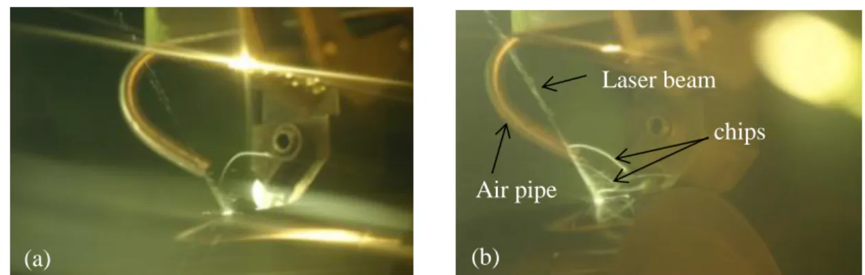
![Figure 2.8 shows the approach used for the LAM experimentation. Process optimization is essential since LAM does not always lead to better results [32]](https://thumb-eu.123doks.com/thumbv2/123doknet/2324099.29876/53.918.125.777.373.614/figure-approach-experimentation-process-optimization-essential-better-results.webp)


Documents relatifs