is an open access repository that collects the work of Arts et Métiers Institute of
Technology researchers and makes it freely available over the web where possible.
This is an author-deposited version published in: https://sam.ensam.eu Handle ID: .http://hdl.handle.net/10985/8997
To cite this version :
Sandra ZIMMER-CHEVRET, Laurent LANGLOIS, Julien LAYE, Jean-Claude GOUSSAIN, Patrick MARTIN, Régis BIGOT - Methodology for qualifying a Friction Stir Welding equipment - In: 7th International Symposium on Friction Stir Welding Awaji Island, Japan, Japan, 20080520 -ISFSW'2008 - 2008
Methodology for qualifying a Friction Stir Welding equipment
Sandra Zimmer
(1), Laurent Langlois
(1), Julien Laye
(2), Jean-Claude Goussain
(2),
Patrick Martin
(1), Régis Bigot
(1)(2)Institut de Soudure - FSW Center 2-4 rue Pilâtre de Rozier
57420 GOIN France
Tel: +33 3 87 56 66 54
(1)Arts et Métiers Paris Tech Metz - LGIPM 4, Rue Augustin Fresnel
57078 Metz Cedex 3 France Tel: +33 3 87375430 [email protected]
Keywords: Friction Stir Welding, Industrialization, Friction Stir Welding Equipment
Abstract: The objective of this research work is the industrialization of the friction stir welding process
in order to provide tools to industrials to select and qualify a machine for their FSW applications. This paper presents a methodology to determine the Friction Stir Welding equipment adequate to an application. The adequate equipment can be every machine that can perform friction stir welds. This paper presents a short review, based on literature survey, of the existing friction stir welding equipments. Then, the methodology developed is presented. It is based on the studying of the interactions between the tool and the workpiece.
1. Introduction
Friction Stir Welding is an innovative welding process. Its main advantages regarding other fusion welding processes are higher weld mechanical properties, low distortion and its automatization and repeatability possibilities. As it is a solid state welding process [1], it gives him the availability to weld almost all type of aluminium alloys, even the one classified as non-weldable because of cracking and porosity in the fusion zone [2]. Furthermore, it meets the need from industrials to join similar or dissimilar aluminium parts together or with other metals like cupper or steel. This should be convincing arguments for industrials to use it.
However, high forces are generated during the welding operation [3] [4], described generally to be the most disadvantage of this welding process. The welding equipment must be rigid enough to satisfy them [5]. Furthermore, the machine should be able to weld complex joint geometry to offer a wide range of applications. So, to produce industrial weld, special dedicated machine were developed. These kinds of equipments, as not standard, are generally expensive. Therefore, the industrials are reluctant to adopt this new technology.
So, if the production cost could be reduced this technology will certainly widespread in terms of applications. One way to reduce the production cost is to choose a standard machine to perform FSW weld, like a robot, milling machine, etc. The machine can be every machine able to apply the requiring forces, tool kinematics with enough precisions to perform FSW welds.
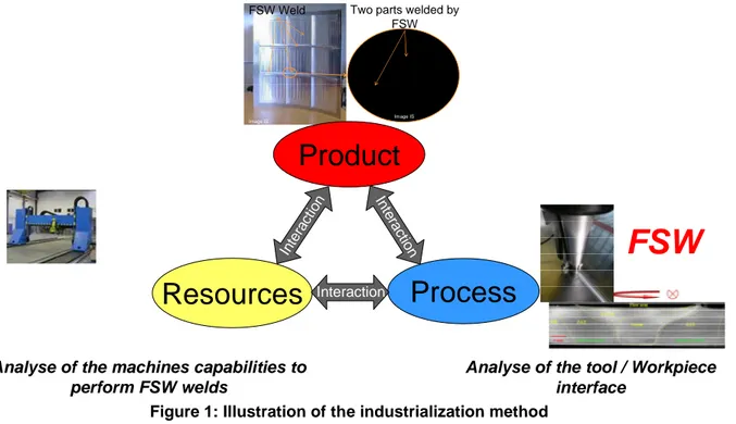
The objective of this research work is the industrialization of the friction stir welding process in order to provide tools to industrials to select and qualify a machine for their FSW applications. The industrialization can be split into three aspects, as illustrated by the Figure 1, the analysis of the product, the process and the resources. These three entities are in interaction. The quality of mechanical parts depends on the expression of specifications (shapes, functions, dimensions, surface quality, and materials), the ability of shaping processes and resource capabilities. Therefore, to qualify a FSW equipment, the methodology focalizes on the study of the Process / Resources interaction. It leads to the determinations of the characteristics parameters in order to write down the technical requirements for the equipment.
FSW Weld
Image IS Image IS
Two parts welded by FSW
Process
Resources
Product
Interaction Inte ract ion Intera ctionFSW
Analyse of the machines capabilities to perform FSW welds
Analyse of the tool / Workpiece interface
Figure 1: Illustration of the industrialization method
The goal of the research work is to identify and to quantify the characteristics parameters to qualify a FSW equipment and the whole clamping device. Therefore a methodology will be developed. The base of the methodology is the definition of the characteristic parameters, for example the forces or torque, to qualify a FSW equipment. These characteristic parameters will be the basis of the establishment of the machine’s technical specifications to choose or design the right equipment for a given application.
This paper presents the methodology to determine the Friction Stir Welding equipment adequate to an application. The adequate equipment can be every machine that can perform friction stir welds. Therefore, this paper presents a short review, based on literature survey, of the existing friction stir welding equipments. Three types of architecture are analysed: milling machines, dedicated FSW machines and industrial robots including Tricepts ones. Then, the methodology developed is presented.
2. The existing friction stir equipment
Today, the machine commonly used to perform FSW, industrially or experimentally, are dedicated FSW machine, modified milling machine, serial and parallel kinematics robots. They all have their advantages and disadvantages but they all have to apply a high load on the tool, a spindle torque and permit the following of the seam. According to the seam geometry, a 2- or 3-dimensional machine will be required [6]. Furthermore, the workpiece geometry will also define the machine required workspace and the joint accessibility.
a. Modified milling machine
Milling machines were the first FSW machine. Furthermore, milling and FSW machine have the same general characteristics [7], spindle rotation, travel speed and CNC control process. They generally offer high stiffness and a good accuracy. They are widely used for machining operation in the industry. Therefore, a wide range of machines exist, from a 2 to 5 axes machines allowing 2 to 3 dimensional welds capabilities. They could apply until 20kN axial load and weld up to 15mm thick aluminium plates [8]. The biggest disadvantage of most the milling machine is unavailability to propose a force controlled operation [4]. But, new milling machines technologies can offer a force controlled process.
b. FSW dedicated machine
FSW dedicated machine allows a force control operation and generally the possibility to weld with the three tool technologies, conventional, retracting and bobbin tool. This system allows controlling the tool / workpiece kinematics and the processing parameters. Each machine is designed to weld, 2- or
3-dimensional and has a predefined workspace. Some of them have a clamping device incorporated. The main advantages of these machines are their high payload capacity due to high framework stiffness. They permit to weld all types of material and a large range of thickness. The machines enabling the welding of 3-dimensional joint generally are composed of a five axes machine based on a gantry and two rotational axes [9]. They generally offer large workspace. The disadvantages of this kind of equipment is its high investments cost and the accessibility of the tool, because there is often one way to achieve a desired location and orientation [9]. The dedicated FSW machines are generally assimilated to high investment cost and low productivity [10]. Therefore, other machine types have been investigated, in order to allow the welding in 3-dimensional configuration, increase productivity and reduce the investment cost.
c. Parallel kinematics robot
FSW on Tricept 805 robot has been developed by GKSS research centre. This kind of machine is commonly used for high speed milling applications [11] Tricept robots are characterized by high stiffness, allowing the application of 45kN down force, and to assure good position accuracy [5]. Tricept ensure the accuracy necessary on machining operations, accuracy probably not required for FSW application. However, it appeared to be a good equipment to perform FSW joint. Unfortunately, this kind of equipment possesses high investments costs and small workspace due to its design [9]. These two characteristics are major obstacle to widespread its industrial FSW utilization.
d. Serial kinematics robots
Modern industrial robots ensure flexibility, multidimensionality and lower investments cost than dedicated FSW machine [12]. They also possess a highly developed user interface for rapid programming [9]. Their big disadvantage is their lack of force / load capacity due to their lack of stiffness [3] and [12]. Therefore, to assure the robot welding capabilities and provide him a wide range of applications, the robot must be a high payload robot. The welding difficulties and limited capacities of a low payload (< 500kg) robot have been underlined in previous research work [3]. Furthermore, the robot must be force controlled during the operation, because it will allow to the robot to adjust for cases where they are insufficient down force caused by structural compliance [13]. The main disadvantage of this technology is the limited process forces applicable. They are limited by the maximum power of the robot engines and the maximum torques of the gears [12]. Furthermore, their lack of stiffness involves the deviation of tool position according to the seam [12] and [14]. Despite these two disadvantages, the industrial robot seems to be a good FSW mean of production. The different publications on the robotic FSW, [3] to [12] show a real development improvement and a real potential for industrial applications. They appear to be a good compromise between complex weld geometry, range of applications, workspace and investments costs. Therefore, they could be the key of the FSW wide spreading. For that reason, the Institut de Soudure and the ENSAM Metz are working on the FSW robotization. They are working on the methodology to qualify a FSW equipment. It will be applied on the robotization of process in order to characterize the robot capacity to perform FSW welds and its applications.
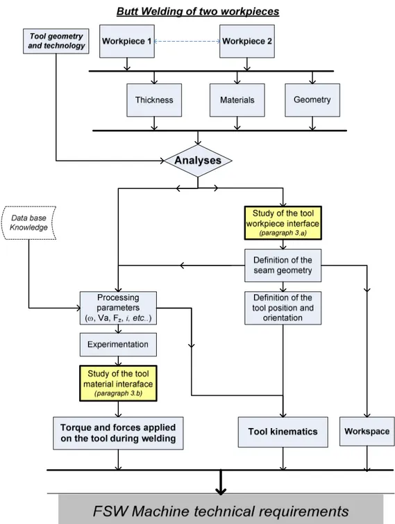
3. Presentation of the methodology developed
The methodology proposed is aimed to write down the technical specifications for a FSW machine dedicated to one or several applications and to qualify it. To achieve this goal, the interactions between the tool / workpiece and tool / material are analysed. The analysis of the tool / workpiece interaction is a global approach. It leads to the determination of the position and orientation of the tool during welding, according to the welding surface. It also defines the workspace required. In the other way, the study of tool / material interaction is a more local approach. It describes the tool position and orientation, according to the welding surface. It also defines the tool kinematics and the mechanical load applied on the tool. The methodology can be illustrated by the Figure 2.
Figure 2: Description of the global methodology to establih the bases of the qualification of a FSW machine.
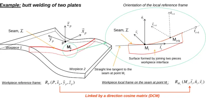
a. Analysis of the tool / workpiece interface - global approach
It is an analysis based on the tool and geometric aspect. It is a global approach. It leads to the definition of the tool position and orientation at each location of the tool path. The welding configuration generally imposes a specific inclination and orientation of the tool with respect to the welded surface [MISHRA, 2005]. The method is based on the study of the seam and the welding surface geometries. The first step is the definition of the seam line, L. L is defined as the line generated by the joining of two surfaces without any gape (Figure 3). The seam L can be described as being a succession of point Mi.
Mi ti r i nr i vr
Surface formed by joining two pieces workpiece interface Straight line tangent to the
seam at point Mi Mi Seam, L P p
x
r
pz
r
py
r
Worpiece 1 Worpiece 2 Mi+k k i tr+ k i nr+ k i v+ rExample: butt welding of two plates
Seam, L
Orientation of the local reference frame
Workpiece reference frame: RP(P,xrp,yrp,zrp) Workpiece local frame on the seam at point Mi : RMi(Mi,ti,ni,vi) r r r
Linked by a direction cosine matrix (DCM) Figure 3: Definition of the seam local frame orientation
For each location Mi of the welded path, a local orthonormal reference frame RMi (Mi, ti, ni, vi) is
defined. The vector ti is tangent to the seam line, L, and oriented according to the welding direction. The vector ni is normal to the plane tangent to the workpiece welded surfaces. The Figure 4 presents some example of the ni definition according to the workpiece geometry. The third vector vi is chosen in order to form an orthonormal reference frame.
1
n
r
2n
r
1 nr n2 r 2 1 2 1n
n
n
n
n
r
r
r
r
r
+
+
=
n
r
Pièce 1 Pièce 2t
r
Plane formed by the joining of the two workpieces’ surface 2 1n
n
n
r
=
r
+
r
Pièce 1 Pièce 2 1n
r
n
n
r
2r
t
r
Workpice 1 Workpice 2
Anvil
1
n
r
Perpendicular to the workpiece 1 surface 2n
r
Perpendicular to the workpiece 2 surfacen
r
Perpendicular to the vector t and to the plane tangent to the welded surfaceM
iM
i
Anvil
Example case 1 Example case 2
Workpice 1 Workpice 2
Figure 4: Illustration of the definition of the vector n definition according to the workpiece geometry
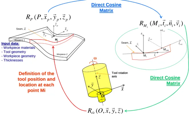
So, the successions of points Mi are defining the tool path and the successive definition of reference
frames RMi are qualifying the welding surface geometry. Thus, for each point Mi the corresponding
reference frame RMi can be linked by direction cosine matrix to a fixed workpiece (or anvil) reference frame RP. The next step is to position and orientate the tool reference frame, RO (O, x, y, z), according to RMi, depending on the welding configuration. The reference frames RO and RMi can also be linked together by a direction cosine matrix. Therefore, it leads to the awareness of the tool orientation and inclination along the seam L. It also defines the position of the tool frame with respect to the workpiece frame, Figure 5.
Input data: Input data:
--WorkpieceWorkpiecematerialsmaterials
--Tool geometryTool geometry
--WorkpieceWorkpiecegeometrygeometry
--ThicknessesThicknesses
Direct
Direct
Cosine
Cosine
Matrix
Matrix
Direct
Direct
Cosine
Cosine
Matrix
Matrix
Definition
Definition
of the
of the
tool position and
tool position and
location
location
at
at
each
each
point Mi
point Mi
)
,
,
,
(
p p p PP
x
y
z
R
r
r
r
Mi Seam, L P p x r p z r p yr Worpiece 1 Worpiece 2 Mi ti r i n r i vr Mi+k k i t+ r k i n+ r k i v+ r Seam, L)
,
,
,
(
i i i i MM
t
n
v
R
ir
r
r
)
,
,
,
(
O
x
y
z
R
Or
r
r
y
r
x
r
Tool rotation axis ω Oz
r
y
r
x
r
Tool rotation axis ω Oz
r
Figure 5: Definition to the tool position and orientation and each location of the welding path To conclude, this global approach leads to the definition of the tool position and orientation at each location of the tool path, the workspace knowledge and the required tool accessibility according to the workpiece reference frame Rp.
b. Study of the tool / Workpiece kinematics and the mechanical interaction
To perform the weld, to assure friction heat and to contain the stirred material under the shoulder, a vertical down force has to be applied by the tool on the surface. Beside this, the tool is animated by a travel velocity and a rotational movement. This combination of these three factors (in bold) assure the heat generation and plastic deformation leading to the generation of the weld. Thus, in order to perform FSW welds, a machine has to apply these three process parameters. The machine also has to ensure the position and inclination of the tool at each location leading to a good stirring and seam tracking. The Figure 6 presents the interaction between the tool and the workpiece during the welding phase. It also schematizes the mechanical load applied by the tool on the workpiece material.Fz
Welding process parameters:
• Down Force Fz [N], • Travel speed [mm/min], • Rotational speed [tr/min]
Anvil Anvil Anvil xr z r O Travel direction vtravel[mm/min] Tilt angle
t
r
ω ω ω ω Schematization of the material flowAnalysis of the tool / workpiece material
interaction Analysis of the tool /
workpiece material interaction Welding direction p y r x
F
r
zF
r
ω,
ω,
ω,
ω,
Cz Workpiece 1 Workpiece 2 O Seam, LLLL Tool Shoulder yF
r
p xr y r xr z r P JointWorkpiece reference frame: RP(P,xp,yp,zp)
r r r
Tool reference frame: RO(O,x,y,z) r r r
Figure 6: Schematization of the mechanical interaction between the tool and the workpiece The tool travel velocity, named vtravel, is defined as being the tool velocity on point O according to the welded workpiece.
This overview leads to the right understanding of which characteristics should have a FSW machine. It points out that the qualification of a FSW machine can be split into two analyses, the relationship between the tool kinematics and the mechanical load generated on the tool and their magnitude. Thus, the mechanical load can be written:
Anvil O Fz z r x r Ftool Travel direction, vtravel[mm/min] ω ωω ω
z
C
y
L
x
L
T
z
F
y
F
x
F
F
z y x O workpiece tool z tool tool workpiece toolr
r
r
r
r
r
r
r
×
+
×
+
×
=
×
+
×
+
×
=
, / /Forces applied by the tool on the workpiece material:
Momentum, on point O, applied by the tool on the workpiece material:
Travel force:
F
F
i
F
i
z tool x=
×
cos
+
×
sin
r
r
r
y
r
Ftool Transverse force: tool yF
F
r
r
=
(1) (2)Figure 7: Mechanical load generated during the welding phase of a FSW operation The torque components Lx and Ly presented in Figure 7 will not be taken into consideration and are assumed to be equal to zero.
Ftool/workpiece and T tool/workpiece are the force and torque applied during welding on the tool and transmitted to the FSW equipment. Thus, they are important for the qualification of a FSW equipment. Futhermore, they remain not constant during the whole welding phase. Therefore it appears important to analyse the welding phases in detail. It leads to the next step of the methodology, the determination of the welding characteristics parameters throughout the analysis of the welding operation and the analyses of the force and torque evolutions.
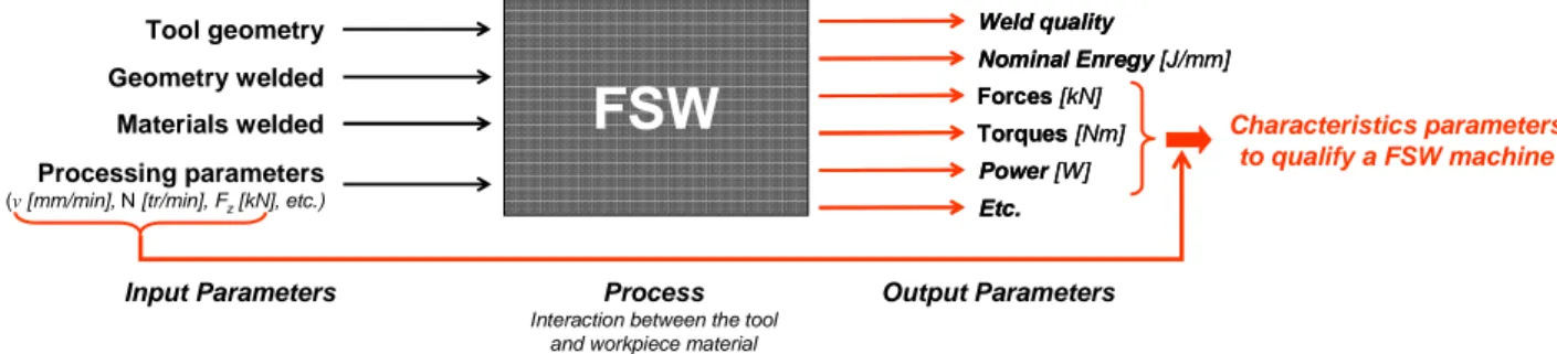
4. Determining the process and machine characteristic parameters
After identifying the parameters relative to the FSW process to ensure the energy and the tool kinematics in order to achieve a sound weld, the next step of the methodology developed focussed on the tool - workpiece interaction during all the welding operation. The process output parameters are dependent on this interaction. The Figure 8 presents the input and output parameters related to a FSW operation. Therefore, to qualify a FSW equipment, an analysis of the forces and torques applied on the tool during welding is necessary.
Forces [kN] Forces [kN] Nominal Enregy [J/mm] Nominal Enregy [J/mm] Etc. Etc.
FSW
Process Interaction between the tooland workpiece material
Torques [Nm] Torques [Nm] Power [W] Power [W]
Processing parameters
(v[mm/min], N [tr/min], Fz[kN], etc.)
Materials welded Geometry welded Tool geometry
Input Parameters Output Parameters
Weld quality Weld quality
Characteristics parameters to qualify a FSW machine
Figure 8: Presentation of the input and parameters related to a FSW operation
Generally the FSW operation is described by two main phases, the plunge and the welding phase [15] and [8]. As the tool - workpiece interaction differs according to the welding phase, it is necessary to decompose the whole welding phase. So, the tool kinematics were analysed leading to the decomposition of the welding phase into six independent sub-phases: plunging, dwell time, acceleration, welding at constant speed, deceleration and pin retracting. The Figure 9 presents the tool kinematics and the corresponding phases during FSW.
Tool pentration Time [s] Plunge P e n e tr a ti o n d e p th Welding at constant speed Dwell time Acceleration Deceleration Tool retracting W e ld in g s p e e d [rpm] [mm] Tool welding speed vtravel min mm R o ta ti o n a l s p e e d
Tool rotational speed
Figure 9: Presentation of the tool kinematics during the welding phase
Each welding phase is investigated separately in order to find out the relevant parameters defining a FSW machine. The tool kinematics, the forces and torques have been monitored and analysed for each welding phases. During dwell time, the kinematics of the tool is concentrated on the rotation. By analysing the forces and torque curves it appears that this phase is not characteristic. So, for the remaining five phases, it is necessary to analyse the tool – workpiece mechanical interaction for each welding phases separately. All the experimentation results given in this document had been performed on the fully instrumented MTS ISTIR-10 machine at the Institut de Soudure.
a.
The plunge:
This phase corresponds to the entrance of the tool into the "cold" material [8]. The process parameters, for a position control operation, are:
• ωplunge [tr/min] The rotational frequency,
• ∆z [mm] The depth of penetration,
• vplunge [mm/min] The penetration velocity
• aplunge [mm/min²] The acceleration of the pin penetration
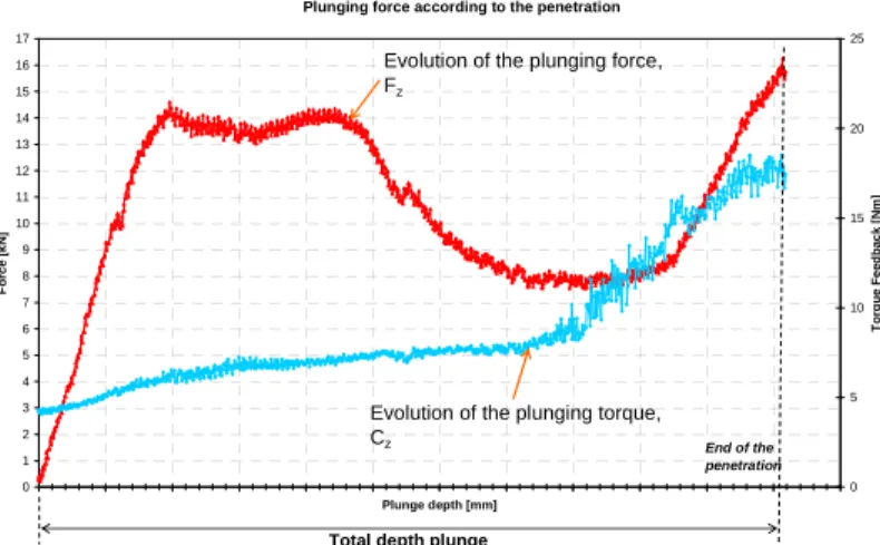
According [8] and [16], the penetration phase is characterized by a brief peak of the vertical effort, when the shoulder comes into contact with the surface. The “peak” intensity should be depending on the penetration velocity [16]. The Figure 10 shows the plunging effort and torque feedback obtained during experimentation. It may be noted that the maximal torque and force are obtained almost simultaneously, at the end of the penetration. In the last 25% remaining penetration, probably when the shoulder touches material displaced upwards by the pin penetration, the curves of the torque and force grow more rapidly until they reach a “peak”. That maximum occurs at the end of the penetration, when the tool shoulder is completely in contact with the plate’s surfaces.
Plunging force according to the penetration
0 1 2 3 4 5 6 7 8 9 10 11 12 13 14 15 16 17 Plunge depth [mm] F o rc e [ k N ] 0 5 10 15 20 25 T o rq u e F e e d b a c k [ N m ] End of the penetration
Evolution of the plunging force, Fz
Evolution of the plunging torque, Cz
Total depth plunge
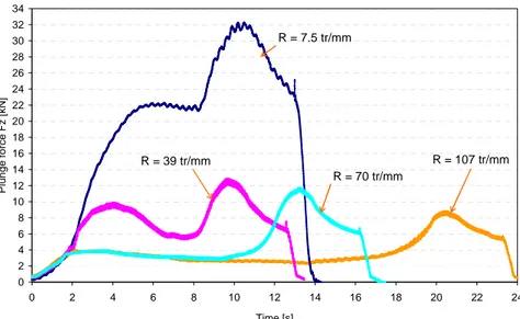
The same force Fz and torque evolution has been observed for other thicknesses and processing parameters. The Figure 11 presents the evolution of the force feedback during penetration for different processing parameters. The evolution presents the same caracteristics.
0 2 4 6 8 10 12 14 16 18 20 22 24 26 28 30 32 34 0 2 4 6 8 10 12 14 16 18 20 22 24 Time [s] P lu n g e f o rc e F z [ k N ] R = 7.5 tr/mm R = 39 tr/mm R = 70 tr/mm R = 107 tr/mm
Figure 11: Evolution of the force Fz during the penetration, for the same plunging depth and different processing parameters
b.
Acceleration phase
After the dwell time, the tool is animated by a movement along the seam. The tool velocity progresses from a velocity equal to zero to the one parameterized. It is the beginning of the weld generation. Therefore, it is also the beginning of the force control regulation. By assumption, when the parameterized speed is reached, this phase is finished.
Process parameters related to the tool kinematics are:
• ω [tr/min] The rotational frequency
• vtravel [mm/min] The travel velocity, vtravel [0 ; vtravel]
• atravel [mm/min²] The acceleration
Process parameters related to the application of the force control activation:
• vforce [kN/min] Force rate,
• aforce [kN/min²] Acceleration rate,
• Fz [kN] The down force
The Figure 12 presents the evolution of the forces in the three directions, (O,x,y,z), and the spindle torque. The effect of the material heating during dwell time can be seen on the decrease of the force Fz and the torque. As the tool is animated by a movement, the travel and the transversal forces are increasing. The torque decrease tendency seems not to be affected, certainly still benefiting from the dwell time material heating. And, the force Fz managed to reach the parameterized force. The machine begins the regulation of the force to maintain it constant until the end of welding operation.
-5 -3 -1 1 3 5 7 9 11 13 15 17 67 68 69 70 71 72 73 74 75 76 77 Time [sec] F o rc e s [ k N ] 0 2 4 6 8 10 12 14 16 18 20 22 24 T o rq u e [ N m ] End of the penetration Plunge Dweel time Acceleration vtravel= 0
Reprensentation of travel speed Fy Fx Cz, Torque Fz vparametrized = vtravel
c.
Welding at constant welding speed
The acceleration phase is followed by a phase where the welding speed, rotational and the down force Fz are maintained constant.
The process parameters related to this phase are:
• ωwelding [tr/min] The rotational frequency
• vtravel [mm/min] The travel velocity
• Fz [kN] The down force
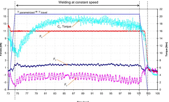
The Figure 13 shows the evolution of the forces and torque during the welding operation at constant speed. As the operation is force controlled, the down force Fz remains constant. After increasing during the acceleration phase, the travel force and transverse force seems to stabilize. The torque begins again to rise, suggesting that the material in front of the tool is “colder”. It seems to stabilize after a few seconds. Then, heat generation is certainly stabilized and provided by the tool kinematics.
-5 -3 -1 1 3 5 7 9 11 13 15 17 73 75 77 79 81 83 85 87 89 91 93 95 97 99 101 103 105 Time [sec] F o rc e s [ k N ] 0 2 4 6 8 10 12 14 16 18 20 22 T o rq u e [ N m ]
Welding at constant speed
Fy
Fx
Cz, Torque
Fz
vparametrized = vtravel
Figure 13: Forces and torque according to the time during the welding phase at constant speed
d.
Deceleration and tool material retracting
At the end of the welding seam, the tool decelerates to reach a speed equal to zero. During this phase, the down force is slacked of smoothly. This down force release leads to the beginning of the tool retracting.
Process parameters related to the tool velocity are:
• ω [tr/min] The rotational frequency,
• dtravel [mm/min²] The deceleration, vtravel [vtravel ;0]
Process parameters related to the application of the force control release:
• vforce [kN/min] Force removal rate
• aforce [kN/min²] Acceleration removal rate,
Process parameters related to the pin removal:
• ∆z [mm] The clearance high
• V [mm/min] The removal velocity
• A [mm/min²] The acceleration
When the tool starts its deceleration, the travel, transverse and torque seem to decrease (Figure 14). At the end of the deceleration, the down forced is released leading to the removal of the pin.
-5 -3 -1 1 3 5 7 9 11 13 15 17 100 100.5 101 101.5 102 102.5 103 103.5 104 Time [sec] F o rc e s [ k N ] 0 2 4 6 8 10 12 14 16 18 20 22 T o rq u e [ N m ] Deceleration Fy Fx Cz, Torque Fz vtravel= 0 vparametrized = vtravel
Figure 14: Forces and torque according to the time during at the end of the welding operation The FSW operation can be considered to be ended as soon as the spindle rotational movement is stopped, when the pin is entirely out of the material.
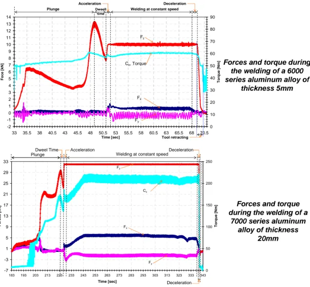
The force and torque evolutions described above are mostly the same according to the aluminium alloy and thickness. The Figure 15 presents the forces and torque evolution for two materials and two thicknesses. -7 -3 1 5 9 13 17 21 25 29 33 183 193 203 213 223 233 243 253 263 273 283 293 303 313 323 333 343 Time [sec] F o rc e s [ k N ] 0 50 100 150 200 250 T o rq u e [ N m ]
PlungeDweel Time Acceleration Welding at constant speedDeceleration
Deceleration Fy
Fx
Cz
Fz
Forces and torque during the welding of a 6000 series aluminum alloy of
thickness 5mm
Forces and torque during the welding of a
7000 series aluminum alloy of thickness 20mm -2 -1 0 1 2 3 4 5 6 7 8 9 10 11 12 13 14 33 35.5 38 40.5 43 45.5 48 50.5 53 55.5 58 60.5 63 65.5 68 70.5 Time [sec] F o c e [ k N ] 0 10 20 30 40 50 60 70 80 90 T o rq u e [ N m ] Plunge Dweell time
Welding at constant speed Acceleration Deceleration Tool retracting Fy Fx Cz, Torque Fz
This tool / workpiece analysis throughout the forces and torque curve, for each welding phase, are essential in order to know how the FSW equipment will statically be loaded. Furthermore, to qualify a FSW machine it is important to have a good understanding of the whole process. This curve analysis had been completed by a numerical analysis on different material and thickness, to gives the maximal, middle and minimum forces and torque occurred during each welding phase. It permits to compare one phase to another, in order to determine which phase will be characteristic to qualify a FSW equipment.
5. Comparing the forces, torque and power for each phases
A study of the maximum, mean and middle value of the forces and torque applied on the tool during each welding phases was conducted for two aluminium alloys, 6000 and 7000 series, and several thicknesses, 3, 5, 7 and 20 mm. The plunge, in the 20mm thick plate, was performed with a drilling hole. All the welding experiments are done with the same tool geometry and the processing parameters chosen led to a sound weld. The charts presented beyond are the maximum values observed. The same tendency has been seen on the middle and mean values. As the machine will first be qualified on a static point of view, the analysis presented in this paper will draw a comparison of the maximum value measured. Thus, phase by phase, the forces Fz, then Fx, Fy and Cz will be analyzed.
a. Comparison of the force F
zover the whole welding phase
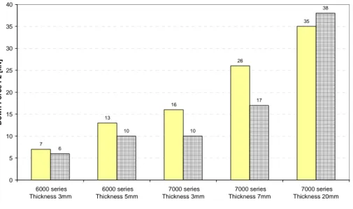
For these experiments, the plunging phase is position controlled and the welding phase is force controlled. Therefore, the down force Fz is not set up and his maximum value is depending on processing parameters. The study reveals that, for most cases, the plunging force is greater than the welding force, Figure 16. This seems to be consistent with the curve displayed on the literature [8]. The maximal plunge force could be reduced by decreasing the plunge velocity [16] or by adding a drilling hole before plunging [8]. For the configuration, welding a 7000 aluminium series of 20mm, the plunging phase was done with the help of a drilled hole. In conclusion, the plunging force has to be considered for the qualification of the structure.
7 13 16 26 35 6 10 10 17 38 0 5 10 15 20 25 30 35 40 6000 series Thickness 3mm 6000 series Thickness 5mm 7000 series Thickness 3mm 7000 series Thickness 7mm 7000 series Thickness 20mm D o w n F o rc e F z [ k N ]
Maximal plunge force Welding force
Figure 16: Comparison between the maximal plunging force and the applied welding force
b. Comparison of the force F
x, F
yover the whole welding phase
The forces Fx and Fy correspond respectively to the travel and transverse force during the acceleration, welding at constant speed and deceleration phases. It has been seen on mostly application that the forces according to the x-direction is predominant during welding at constant speed. There is a major difference between the welding phase at constant speed and the three other namely for the strongest thickness. In contrary, the maximal force according the y-direction occurs during the plunging phase, except when the plunging phase is helped by a drilled hole.
Forces according to the x-direction Forces according to the y-direction 1.3 1.6 0.7 1.6 2.9 1 1.2 0.7 1.1 3.9 0.9 0.9 0.7 1.8 5.4 0.7 0.8 0.5 1.5 2 0 1 2 3 4 5 6 6000 series Thickness 3mm 6000 series Thickness 5mm 7000 series Thickness 3mm 7000 series Thickness 7mm 7000 series Thickness 20mm F o rc e a c c o rd in g t o t h e y -d ir e c ti o n [ k N ]
Plunging Acceleration Welding at constant speed Deceleration
0.5 1.2 0.6 2.2 3.2 0.6 1.4 0.8 1.5 3.4 0.7 1.1 1 2.7 10.8 0.5 1 0.7 2.4 3.2 0 2 4 6 8 10 12 6000 series Thickness 3mm 6000 series Thickness 5mm 7000 series Thickness 3mm 7000 series Thickness 7mm 7000 series Thickness 20mm F o rc e a c c o rd in g t o t h e x -d ir e c ti o n [ k N ]
Plunging Acceleration Welding at constant speed Deceleration
Figure 17: Comparison of the force according to the x and y direction during the welding phase for different configuration
The Table 1 presents a comparison between the forces Fx and Fy with Fz. The forces Fx and Fy are not insignificant against the forces Fz. They represent 8 to 16% of the forces Fz.
Plunge Acceleration Welding at
constant speed Deceleration
Fx/Fz*100
[%] 9 10 16 10
Fy/Fz*100
[%] 11 11 12 8
Average value for every configuration
Table 1: Comparison between the forces in the plane (O,X,Y) with the down force Fz
c. Comparison of the force C
zover the whole welding phase
The Figure 18 presents the evolution of the spindle torque over the 4 welding phases. It appears that the torque is slightly higher on the plunging phase when the operation is done without a drilled hole. 42.5 61.5 63 103 150 42.5 60 60 100 90 36 61 42 93 216 43 61 20 90 205 0 50 100 150 200 250 6000 series Thickness 3mm 6000 series Thickness 5mm 7000 series Thickness 3mm 7000 series Thickness 7mm 7000 series Thickness 20mm S p in d le t o rq u e f e e d b a c k [ N m ]
Plunging Acceleration Welding at constant speed Deceleration
d. Comparison of the power developed on the spindle over the whole welding
phase
The total power can be defined by:
] / [ ] [ ] / [ ] [ ] [
max max max
s m N s rad Nm w plunge z plunge z
F
v
C
Power
≤
×
ϖ
+
×
Power related to the spindle rotationPower related to the tool motion
During plunge:
] / [ ] [ ] / [ ] [ ] [max max max
s m N s rad Nm w travel x welding z
F
v
C
Power
≤
×
ϖ
+
×
Power related to the spindle rotationPower related to the tool travel
During welding:
(3)
(4)
The numerical determination of the power reveals that the power related to the motion of tool, according to the direction x or z direction during plunging, is negligible against the total power. The Table 2 presents the ratio between the power necessary to ensure the tool motion and the total power. The power relative to the tool motion is negligible against the total power, whatever the configuration, i.e. it is independent of the thicknesses and material welded.
Plunge Acceleration Welding at
constant speed Deceleration Power ralated to the tool
motion Total Power
[%] 0.3 0.1 0.1 0.1
Average value for every configuration
v
F
C
v
F
z×
+
×
×
max max _ maxω
Table 2: Comparison of the power relative to the tool travel motion and the total power Furthermore, [SIMAR, 2004] demonstrated experimentally that the power relative to the tool motion was also negligible whatever the travel speed. Therefore, it can be assumed that the power is defined by:
welding z
C
Power
=
×
ϖ
(5)
e. Dynamic behaviour of the forces
To qualify a FSW equipment, it is also important to take into consideration the dynamic behaviour of the forces, because it will be send back to the machine and to the clamping device. By analysing the forces Fx and Fy an oscillation phenomena have been highlighted. A frequency analysis has then been performed through a Fast Fourier Transform analysis. Into the Fx and Fy oscillations, there are one low frequency and one frequency corresponding to the tool rotational speed. [6] mention a variable load on the tool due to a combination of the tool rotation and the two forces components Fx and Fy. This could perhaps explain the low frequency response visualized in the experiments. The Figure 19 presents the experimental results. The analysis was performed on a sample corresponding to the welding at constant speed phase.
Fast Fourier Transform on the Fx Force 0 0.2 0.4 0.6 0.8 1 1.2 5858.2 58.4 58.6 58.8 59 59.2 59.4 59.6 59.860 60.2 60.4 60.6 60.8 6161.2 61.4 61.6 61.8 62 Time [sec] F o c e [ k N ] Fx Corresponding FFT 0 0.2 0.4 0.6 0.8 1 1.2 5858.2 58.4 58.6 58.8 59 59.2 59.4 59.6 59.860 60.2 60.4 60.6 60.8 6161.2 61.4 61.6 61.8 62 Time [sec] F o c e [ k N ] Fx Corresponding FFT
Zoom on the Fx oscillation phenomena
0 0.01 0.02 0.03 0.04 0.05 0.06 0.07 0.08 0.09 0.1 0 1 2 3 4 5 6 7 8 9 10 11 12 13 14 15 16 17 18 19 20 21 22 23 24 25 Frequency [hz] A m p li tu d e Frequency corresponding to the tool rotational
speed
Figure 19: Analysis of the Fx dynamic response by comparing the forces measured and the FFT results
It seams important to take into account this phenomena because it could impact the machine and clamping device on a vibration point of view implying the tool deviation from the welding path. Therefore, the Fx and Fy responses have to be investigated more deeply in order to understand the origin of the phenomena.
f. Conclusion of this analyse
The study done on the forces and torques intend to determine statically a FSW equipment. It enables to concentrate on the phases which are characteristics. It appears that Fy, Fz and Cz are predominant during the plunge and welding at constant phases. Furthermore, it appears that Fx and Fy are not insignificant according to Fz and should be taken into account for an equipment static determination. This knowledge will permit to focus on these phases’ process parameters in order to reduce the forces and torque applied on the tool. Thus, it will enable the FSW on machine with load / rigidity weaknesses. On the other hand, another way to reduce the process forces is to work on the tool geometry [8].
6. Application
The application presents the welding of two dissimilar aluminium alloys, 2000 with 6000 series. The Figure 20 presents the geometry of the two workpieces welded. The thickness of the two parts is the same. Worpiece 1 6000 series Worpiece 2 2000 series Circular FSW weld P p
x
r
pz
r
p yrWorkpiece reference frame: RP(P,xp,yp,zp)
r r r P p xr p z r p y r
Tool welding path
r
Figure 20: Presentation of the workpiece’s geometries
It is assumed that the workpiece surfaces form a perfect plane. The operation will be performed with a flat shoulder tilted at 0 degree angle. The 2000 aluminium alloy was placed on the advancing side. For this application, it didn’t seem necessary to move the tool into one workpiece. With the assumption that the welded surfaces form a perfect plane and no gap remains after positioning the two workpieces, it could be assumed that for every location of the seam L, the point Mi is congruent with the point O. So, by deduction, for this configuration, the reference frames RMi and RO are superimposed. Therefore, the tool workpiece configuration required for this application, can be described on Figure 21.
Fz
ω
x ti r r = z ni r r = O=Mi Workpiece 1 6000 Workpiece 2 2000 Anvil)
,
,
,
(
i i i MM
t
n
v
R
ir
r
r
)
,
,
,
(
O
x
y
z
R
Or
r
r
=)
,
,
,
(
i i i MM
t
n
v
R
ir
r
r
)
,
,
,
(
O
x
y
z
R
Or
r
r
=The direction cosine matrix linking RMito RO is:
=
⇒1
0
0
0
1
0
0
0
1
O Mi R RA
(6)Position of the location of the point O:
0
r
=
O
M
i (7) eFigure 21: Schematization of the tool position and orientation according to the local reference frame RMi
a. Analysis of the tool / workpiece interface - global approach
The tool / workpiece global approach leads to the definition of the seam L. It also defines the orientation of the reference frame RMi at each location Mi of the seam. The Figure 22 presents the seam L. For some points Mi on L, the reference frame RMi is defined. As the welding path is a circle, the vector ti will be defined as being tangent to the circle oriented according to the welding direction.
Welding
direction
M
i it
r
iv
r
ni rP
px
r
p y rr
γγγγ
v
travelSeam,
L
= Welding path
Figure 22: Illustration of the definition of the seam LLLL and the orientation of the reference frame RMi at different location
The orientation of the reference frame RMi is changing among the welding path. The orientation can be defined with the rotation angle γ. Therefore, the location and orientation, according to RP, of the reference frame RMi can be defined as:
The direction cosine matrix linking RMito Rpis:
−
−
−
=
⇒1
0
0
0
sin
cos
0
cos
sin
γ
γ
γ
γ
p Mi R RA
Position of the location of the point M
i:
(8)
PM
ir
x
pr
y
pr
r
⋅
×
+
⋅
×
=
cos
γ
sin
γ
(9)
Figure 23: Definition of the orientation of the reference frame RMi according to RP
Thus, the position and orientation of the tool, according to the reference frame RP can be defined with the equations (6), (7), (8) and (9). The required machine workspace for this application will be defined by the size of the circle diameter.
b. Study of the tool kinematics and the mechanical interaction
The next step is to determine the tool kinematics and the mechanical interaction between the tool and the workpiece material. From a kinematics point of view, the geometry welded is a planar circular joint, requiring a two dimensional tool motion to fellow the seam. Thanks to the direction cosine matrix linking RMi to RP, the travel speed can be written according to the fixed workpiece reference frame:
p travel p travel P workpiece tool
v
x
v
y
v
r
/,
=
−
×
sin
γ
⋅
r
+
×
cos
γ
⋅
r
(10)So, according to [6] to perform this FSW weld, 4 degrees of freedom are required. These degrees of freedom can be given to the FSW equipment or to the workpiece holding fixture. By assumption, the holding fixture is fixed and all the degrees of freedom are possessed by the FSW equipment. Thus, to perform this weld, a 3-axis milling machine or a serial and parallel kinematics or a 3-axis dedicated FSW machine could perform the weld. If the tool had a concave shoulder, the tool would be tilted by a certain angle. To weld this application with a tilted tool, a supplementary axis would be needed. Therefore, a 4-axis machine will be required.
The processing parameters, Fz, ω and vtravel are chosen in order to produce a sound weld. To determine these parameters, straight butt welds were performed with the same tool, materials and thicknesses. Workpiece 2 - 2000 Anvil
v
travelω
Image ENSAM Workpiece 1 - 6000 FzFigure 24: Configuration to determine the welding parameters
The processing parameters used to perform the circular weld are the ones determined by the welding of the straight butt welds. The experiments show that the processing parameters determined on a straight weld can be applied to a circular weld in our case. The welds obtained were sound welds, for both applications. During these tests, the forces in the three directions and the torque were measured on the ISTIR 10 gantry machine at the Institut de Soudure. The welding equipment will have to apply the forces and torque required to perform FSW along the circular welding path. Therefore, at each location of the point Mi, the mechanical interaction between the tool and the material is known for each welding phases. The Figure 25 presents the maximal forces and torque according to the tool location on the circle. By comparing the axial and transverse forces occurring during straight butt welding and circular welding, major differences has been seen. The maximal values monitored could be different until 50% depending on the welding phase. The Table 3 presents the results obtained
93.90 124.20 93.10 98.60 100.00 51.20 18.40 3.60 4.00 14.00 2.70 2.30
Circular butt welding
19.60 2.90 4.30 14.20 2.70 4.50
Straight butt welding
Cz [Nm] Fx [kN] Fy [kN] Cz [Nm] Fx [kN] Fy [kN]
Welding at constant speed phase Acceleration phase 93.90 124.20 93.10 98.60 100.00 51.20 18.40 3.60 4.00 14.00 2.70 2.30
Circular butt welding
19.60 2.90 4.30 14.20 2.70 4.50
Straight butt welding
Cz [Nm] Fx [kN] Fy [kN] Cz [Nm] Fx [kN] Fy [kN]
Welding at constant speed phase Acceleration phase [%] welding butt Straight welding butt Circular
Table 3: Comparison of the forces and torque measured during circular and straight butt welding. The given values are mean values measured on different successful trials realized
The deference measured could be explained by:
• the different clamping devices,
• the workpiece positioning, some gap could remain between the workpiece due to the circular geometry of the seam,
• the different tool / workpiece kinematics,
• the tool seam deviation into one workpiece, due to seam tracking defect or machine deformation due to the tool / workpiece mechanical interaction.
The origin of these differences and a more detailed forces curve analysis are part of the future research work. Therefore, it is important to take into consideration these differences when qualifying a FSW equipment by for example applying a safety factor when using the axial and transverse forces monitored during straight butt welding.
Angle
[°]
Phase
Measured forces and
torque applied on point O
Tool kinematics
applied on point O
[ ]
0
;
10
∈
γ
[
10
;
355
]
∈
γ
[
355
;
360
]
∈
γ
0
=
γ
Plunge Acceleration Welding at constant speed Deceleration z w O w z v v plunge workpiece tool plunge workpiece tool r r r r ⋅ = ⋅ = , / /]
[
14
,
]
[
5
.
11
5
.
4
3
/ /Nm
z
O
T
kN
z
y
x
F
workpiece tool workpiece toolr
r
r
r
r
r
⋅
=
⋅
+
⋅
+
⋅
=
z w O w t v v welding workpiece tool i travel workpiece tool r r r r ⋅ = ⋅ = , ] ; 0 [ / / z w O w t v v welding workpiece tool i travel workpiece tool r r r r ⋅ = ⋅ = , / /]
[
20
,
]
[
11
4
3
/ /Nm
z
O
T
kN
z
y
x
F
workpiece tool workpiece toolr
r
r
r
r
r
⋅
=
⋅
+
⋅
+
⋅
=
z w O w t v v welding workpiece tool i travel workpiece tool r r r r ⋅ = ⋅ = , ] 0 ; [ / / ] [ 17 , ] [ 11 5 . 3 5 . 1 / / Nm z O T kN z y x F workpiece tool workpiece tool r r r r r r ⋅ = ⋅ + ⋅ + ⋅ = P p z r p yrθθθθ
accelθθθθ
weldingθθθθ
decel Welding directionv
travelγγγγ
=0
P p z r p yrθθθθ
accelθθθθ
weldingθθθθ
decel Welding directionv
travelγγγγ
=0
]
[
19
,
]
[
15
4
2
/ /Nm
z
O
T
kN
z
y
x
F
workpiece tool workpiece toolr
r
r
r
r
r
⋅
=
⋅
+
⋅
+
⋅
=
Figure 25: Presentation of the forces and torque according to tool location on the welding path These forces and torque are used to determine the solicitation on the selected FSW equipment. The forces and torque are determined at each machine axis. After choosing one machine, the calculated torque and forces can be compared to the maximal admissible motor torque and forces at each machine axis. If the calculated torque and forces are lower than the admissible one at each machine axis, then the chosen machine can be assumed to be statically qualified for this application. The realization of the application on the chosen machine will confirm that the machine is dynamically able
to perform this FSW application. The required spindle power is also defined and can be compared to the maximal machine spindle power.
The knowledge of the forces and torque applied on the workpieces also permit to qualify the anvil and the whole clamping device.
The static determination of the welding device has for goal to make a pre-selection among the one existing. It also permits to pre dimension the equipment, motors, gears, during the FSW machine design.
7. Conclusion and perspectives
The presented work is the foundation of the methodology developed on this research work. The first step of this methodology was the study of the whole welding phase. The analysis was decomposed into a global aspect defining the seam geometry aspect and a local aspect in order to determine the tool workpiece interaction. The welding phase were decomposed it into six characteristic sub-phases. For each sub-phase, the welding processing parameters were defined and the resulting forces and torque were analysed. It provides a good understanding of the forces and torque evolution during a Friction Stir Welding operation. These knowledge are important to qualify a FSW equipment. The forces and torque applied on the tool during welding will be the input data to determine the operation feasibility on a specific machine. This methodology was applied to the circular welding of dissimilar material.
The future work will be concentrated on the welding capacities of different machines. With the forces and torque as input data, the forces and torque will be calculated on each machine’s axis and compared to the admissible ones. Then, the most favourable position of the workpiece inside the machine’s workspace, i.e. the one allowing the lowest motor torque and the best tool accessibility will be searched. On the other hand, a work will be done on the processing parameters, through the determination of the process windows, to reduce the forces and torque applied on the tool workpieces interface in order to facilitate the use of a specific machine.
8. Acknowledgment
The authors would like to thanks the Region Lorraine and the Moselle department to finance this research project.
9. References
[1] W.M. Thomas, E.D. Nicholas, J.C. Needham, M.G. Murch, P. Templemith, C.J. Dawes Patent Application No. 9125978.8 (December 1991)
[2] R.S Mishra, Z.Y. Ma
Friction Stir Welding and processing
Materials Sciences and Engineering R 50 (2005) I-78
[3] C.B. SMITH
Robotic Friction Stir Welding using a Standard Industrial Robot
2nd International FSW Symposium, June 2000
[4] D. EREINER
Prozessmodelle zur statischen Auslegung von Anlagen für das Friction Stir Welding
ISBN: 3-8316-0650-1 (September 2006)
[5] A. von STROMBECK, C. SCHILLING, J.F. dos SANTOS Robotic Friction Stir Welding – Tool Technology and Applications
2nd International FSW Symposium, June 2000
[6] YAVUZ
[7] M. PONTE, J. ADAMOWSKI, C. GAMBARO, E. LERTORA
Low-cost transformation of conventional milling machine into a simple FSW work station
Advanced Manufacturing and Technology, CISM Courses and Lectures No.486, Springer Wien New York, 2005. ISBN: 10-3-211-26537-6 p.357-365
[8] Prof. Dr.-Ing. Michael F. ZAEHL, Prof. Dr.-Ing. Dieter EITEINER, Dipl.-Ing Loucas PAPADAKIS
Friction Stir Welding with modern milling machines. Requirements, Approach and Application
5th International FSW Symposium, 2004
[9] M. SORON
Towards Multidimensionality and Flexibility in Friction Stir Welding Using an Industrial Robot System
Recent Advances in Friction Welding and Allied Processes, Dubrovnik, Croatia, 2007
[10] C.B. SMITH
Robotic Friction Stir Welding using a Standard Industrial Robot
4th FSW Symposium, 2003
[11] R. Zettler1, S. Lomolino1, J. F. dos Santos1, T. Donath1, F. Beckmann1, T. Lippman1, D. Lohwasser
A Study on Material Flow in FSW of AA 2024-T351 and AA 6056-T4 Alloys
5th International FSW Symposium, 2004
[12] G; VOELLNER, F. ZAEH, J. SILVANUS, O. KELLENBERGER Robotic Friction Stir Welding
AeroTech Congress & Exhibition, Los Angeles, California, September 17-20, 2007
[13] Reginald Crawford, George E. Cook and Alvin M. Strauss Modelling of friction stir welding for robotic implementation
Int. J. Modelling, Identification and Control, Vol. 1, No. 2, 2006
[14] G. VOELLNER
3-D FSW using a modified high payload robot
6th International FSW Symposium, 2006
[15] S. SHEIKHI
Herstellung und Bewertung der Umformbarkeit von reibrührgeschweissten Tailored Blanks aus Aluminiumlegierungen
Ph.D. Thesis –University of Duisburg-Essen - 2005
[16] A. SIMAR
A multiscale multiphysics investigation of aluminium friction stir welds from thermal modelling to mechanical properties through precipitation evolution and hardening