Science Arts & Métiers (SAM)
is an open access repository that collects the work of Arts et Métiers Institute of
Technology researchers and makes it freely available over the web where possible.
This is an author-deposited version published in: https://sam.ensam.eu Handle ID: .http://hdl.handle.net/10985/10825
To cite this version :
Mariana STAIA, Eli-Saul PUCHI-CABRERA, Y.Y. SANTANA, J.G. LA BARBERA-SOSA, Alain IOST, Didier CHICOT, Yeczain PEREZ DELGADO, Patrick DE BAETS - Increase of the load carrying capacity of aluminium 2024-T3 by means of a NiP-CRC-DLC coating - International Journal Sustainable Construction & Design - Vol. 4, n°2, p.16-23 - 2013
Any correspondence concerning this service should be sent to the repository Administrator : archiveouverte@ensam.eu
INCREASE OF THE LOAD CARRYING CAPACITY OF
ALUMINUM 2024-T3 BY MEANS OF A NiP-CrC-DLC COATING
M. H. Staia
1,4*, E. S. Puchi-Cabrera
1,2,3,Y.Y. Santana
1, J. G. La Barbera-Sosa
1, A. Iost
4, D.Chicot
2, Y.
Perez Delgado
5, P. de Baets
51 Escuela de Ingeniería Metalúrgica y Ciencia de los Materiales, Facultad de Ingeniería, Universidad Central de Venezuela, Los Chaguaramos, Caracas 1041, Venezuela, mhstaia@gmail.com
2 Université Lille Nord de France, F-59000 Lille; USTL, LML, CNRS, UMR 8107, F-59650 Villeneuve d’Ascq, France.
3 Academia Nacional de Ingeniería y Hábitat, Palacio de las Academias, Dirección Postal 1723, Caracas 1010, Venezuela.
4 Arts et Métiers ParisTech – Centre de Lille, 8, Boulevard Louis XIV, 59000 Lille Cedex, France 5 Ghent University, Department of Mechanical Construction and Production, Soete Laboratory, Technologiepark
Zwijnaarde, 903B-9052 Zwijnaarde, Belgium.
Abstract: The present investigation has been conducted in order to evaluate the tribological behavior of an AA2024-T3 aluminum alloy, coated with a NiP-CrC-DLC coating. The effect of NiP as intermediate layer was evaluated by carrying out calculations using ELASTICA© in order to determine its adequate thickness needed to avoid the plastic deformation of the substrate, ensuring then the integrity of the coating. To evaluate the efficiency of these calculations, a number of dry sliding wear tests were performed employing a ball-on-disk configuration, where alumina balls of 6 mm in diameter were used as counterpart. The sliding wear tests were carried out up to a sliding distance of 800 m, with a normal load of 5 N, a linear speed of 5 cm/s and a contact radius of 3 mm. The wear tracks were analyzed by means of scanning electron microscopy (SEM) techniques coupled with energy dispersive spectroscopy (EDS). The wear volume was determined by means of optical profilometry. The results indicate that, under the present testing conditions, the NiP-CrC-DLC coating exhibits a satisfactory behavior from the mechanical stability point of view when the thickness of the NiP layer is higher than 60 µm, since no surface failures were observed at the end of the tests. For the coated system, the magnitude of the friction coefficient was found to be of approximately 0.1 and that of the wear rate was of about 2.31 ± 0.09 x 10⁻¹⁶ m3/N.m. On the contrary, for the uncoated substrate, the friction coefficient was of approximately 0.5 and the wear rate of 5.46 x 10⁻¹³ m3/N.m, that is to say, 3 orders of magnitude greater than that determined for the coated system.
Keywords: AA2024-T3 aluminum alloy, duplex coatings, NiP, DLC, nanostructured coatings, PAPVD, sliding wear.
1. INTRODUCTION
Aluminum and its alloys exhibit excellent properties such as very high specific strength (strength/density), high toughness, ease of manufacture (major advantage being extrusion), long term performance, no low temperature brittle fracture, readily joinable by welding or mechanical riveting and easily recyclable. All these properties have conferred them an important place traditionally in the aerospace and automobile industries and lately, even in the fabrication of medical devices, where aluminum alloys may have a significant role to play with the potential to reduce manufacturing costs and to give ergonomic advantages to the surgeon due to a reduction in instrument mass [1].
However, the aluminum alloys show poor tribological resistance, as well as corrosion related problems such as localized corrosion, which limit their use for components that have to withstand either contact conditions or harsh environments or both. In order to overcome these drawbacks, extensive research was carried out since their development and different surface engineering methods were considered such as anodizing, heat treatment, laser modification, cladding, PVD and CVD techniques among others, able to improve their performance. Sometimes, it is found that the benefits gained in terms of corrosion protection could be offset by detrimental effects on fatigue performance or wear and vice versa [2].
One of the materials that have gained utmost importance as an attractive candidate for surface protection of these light alloys is diamond-like carbon (DLC) coating due to its high hardness, low friction nature, high chemical stability and excellent corrosion resistance. Unfortunately, when this type of coating is deposited on light alloys, the large Young’s modulus mismatch between coating and substrate coupled with the existence of residual stresses, resulted in a poor load carrying support, which produces the cracking of the coating that is unable to follow the plastic deformation of the substrate.
As consequence, the load-carrying capacity related to the ability of the coating/substrate system to withstand the normal and tangential forces created by the system in a way that the functional properties of the coated system will remain unchanged, has constituted a main concern from the pioneering research carried out by Bull [3], related to this type of coatings, up to the present days.
The application of hard coatings on aluminum alloys that will permit the endurance of much higher contact stresses than would normally be the case of a bare alloy, requires either the use of different interlayers which act as load-supporting such as an micro-arc discharge oxidation alumina layer [4], a HVOF WC-CoCr thermal spray coating [5], an electrolytic Ni plating coating [6], the use of multilayers [7, 8] or gradient layers [9, 10], capable to decrease gradually the existing differences in properties between substrate and coating, amongst others.
Therefore, the present investigation has been conducted in order to evaluate the tribological performance of a system where an intermediate layer of electroless nickel has been used between the DLC (a-C:H)/CrC) coating top layer and the AA2024-T3 substrate, in order to provide a sufficient load carrying capacity. Both the electroless NiP and DLC coatings were deposited industrially.
2. MATERIALS AND EXPERIMENTS
2.1 Determination of the minimal thickness of the intermediate NiP layer in order to avoid plastic deformation of the substrate.
Prior to the sample deposition, a number of calculations were carried out in order to determine the adequate intermediate NiP layer thickness needed to avoid the plastic deformation of the substrate. Such calculations were conducted employing ELASTICA©, a commercial software, which uses an extended Hertzian theory to solve elastic contact problems of layered structures. In this way, it is possible to ensure the integrity of the DLC coating, since the failure of such films depends strongly on the mechanical properties of the substrate.
It is well known that for the contact plane-sphere, at the beginning of the wear test, the developed stresses present their maximum values, which results in the maximum deformation of the substrate.
The elastic properties of both DLC (known industrially as Dymon-iCTM, which is a hydrogenated amorphous DLC coating-a-C:H) and the NiP electroless coating, used in the present calculations, have been already determined and published elsewhere [11-13] (see Table 1). However, some of the mechanical properties shown in this Table were found from the existing literature on this topic and are indicated accordingly.
In the calculations, for the purpose of simplification, the thickness of DLC + CrC coatings was taken as 2.2 µm, considering only one film with similar properties, since the chromium carbide is likely to contain some H, although not as much as the top layer of the a-C:H coating. It has also been reported that the top layer coating could have approximately 30-40 at% H, with a small residual content of Cr, as consequence of the deposition procedure employed [13].
The mechanical behavior of the adopted duplex structure was evaluated by the analytical calculation of the elastic contact deformation fields under a spherical indenter for the cases of Hertzian contact conditions. The contact conditions: an alumina spherical indenter of 3000 µm radius (Preciball USA Inc.) and 5 N applied normal load, were also used during the tribological characterization, since it was stated that for the load-carrying capacity evaluation of the coating/substrate systems, the ball-on-disc test configuration provided the most relevant information [16].
Table 1. Characteristics and mechanical properties of the system under study Material Thickness (µm) E (GPa) HV (GPa) ν σ(GPa) y Al2024-T3 alloy infinite 71.8 [14] 1.50 0.33 [14] 0.345 [14] NiP electroless coating To be determined 160 [11] 7 [11] 0.30 [11] 2.30 (14) Alumina ball - 360 17 0.20 23 [15] Dymon-iC ™ 2.2[12] 146 [13] 18[13] 0.3 10[15]
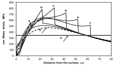
The results obtained from ELASTICA© are shown in Figure 1, where two system architectures were considered: alumina ball/AA2024-T3 and alumina ball/DLC/NiP/AA2024-T3. The graph represents the variation of the calculated von Mises stress distribution for both configurations versus depth, for different NiP interlayers thicknesses. The value of the aluminum yield strength is also represented on the graph.
Figure 1. Variation of the von Mises stress with depth for both system architectures under study.
a: σmax = 560 MPa at d = 12 µm for NiP interlayer = 10 µm; b: σmax = 780 MPa at d = 22 µm for NiP interlayer = 20 µm; c: σmax = 810 MPa at d = 32 µm for NiP interlayer = 30 µm; d: σmax = 730 MPa at d = 42 µm for NiP interlayer = 40 µm; e: σmax = 630 MPa at d = 28 µm for NiP interlayer = 50 µm; f: σmax = 645 MPa at d = 24 µm for NiP interlayer = 60 µm; g: σmax = 480 MPa at d = 27.13 µm for the uncoated AA 2024-T3 substrate; h: yield stress of AA 2024-T3 substrate = 345 MPa.
It can be clearly seen that for the NiP interlayer of 60 µm in thickness, the maximum Von Mises stress of 645 MPa takes place at a depth of approximately 24 µm, i.e. inside the NiP coating, without exceeding its yield stress value of 2300 MPa. Moreover, from the calculations under Hertzian (only normal load) contact conditions it was determined that the contact radius for this system is of 46.3 µm and the principal stress σ1 = 1 GPa for x=0, as compared to 56 µm and σ1 = 0.65 GPa, respectively, the later corresponding to the alumina ball/uncoated AA2024-T3 substrate system. This increase in the compressive stress was attributed to the increase in the contact stiffness, as consequence of the introduction of NiP intermediate layer coupled with the redistribution of the surface contact stresses. A similar increase has also been reported by Bemporad et al. [17] for the PVD/HVOF duplex coating deposited onto a Ti6Al4V substrate
Furthermore, it is noticed that at a depth of 60 µm, corresponding to the NiP intermediate layer, and for a normal load of 5 N, the von Mises stress value is less than 0.345 GPa, which corresponds to the value of the yield stress of AA 2024-T3 substrate, indicating that no plastic deformation of the latter takes place.
Taking these calculations into account, it was decided to consider the deposition of the electroless NiP onto the aluminum alloy substrate, as an intermediate layer, followed by a thin DLC based top layer.
2.2 Coated system
Samples of an aluminum 2024-T3 alloy were mirror polished (Ra = 0,04 ± 0,01µm by means of standard metallographic procedures. The NiP electroless coating with 11%P and a thickness of 65 ± 1µm and Ra = 0,20 ± 0,01µm was deposited by Reliable Plating Inc. (USA). Subsequently, a DLC hydrogenated coating, commercially known as Dymon-iC TM (hydrogenated a-C:H) was deposited by Teer Coatings, England, by means of closed field unbalanced magnetron sputtering ion platting (CFUBMSIP), coupled with plasma assisted chemical vapor deposition (PACVD). In order to ensure a better adhesion of the DLC coating, a Cr film was deposited on top of the electroless NiP, followed by a coating of CrC and finally the a-C:H film. The sample preparation prior to deposition and the complete description of the procedure have been reported elsewhere [12, 13].
2.3 Tribological tests
Sliding wear tests were carried out in air (55±5% humidity) up to a sliding distance of 800 m, with a normal load of 5 N, a linear speed of 5 cm/s and a contact radius of 3 mm, employing an alumina ball of 6 mm diameter, according to the ASTM G99-95. All the reported results represent mean values of at least 3 test runs. The wear tracks were analyzed by means of scanning electron microscopy (SEM) techniques coupled with energy dispersive spectroscopy (EDS). The wear volume was determined by means of a Zygo optical profilometer, which allowed the calculation of the wear constant, k (m3/Nm).
3. RESULTS AND DISCUSSION
3.1. Friction coefficients and wear volume
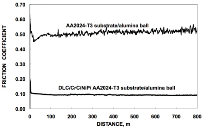
The variation of the friction coefficients with the sliding distance for both systems under study are presented in Figure 2. As it was expected, the friction coefficient for the alumina/AA2024-T3 alloy has a higher value as consequence of the adhesion phenomena, which take place between the harder alumina pin and the alloy. In this case, the stationary friction coefficient value was achieved at around 150 m, with an average value of 0.5. During the test, the adhered alloy substrate undergoes strain hardening and subsequently fatigue, as a consequence of the cyclic nature of the test, allowing therefore the formation of harder debris, which remain in the contact. These are embedded on the aluminum alloy, giving rise to a new surface that is much harder than the former one.
For the alumina/NiP/DLC system, values of the steady friction coefficient of around 0.1 were obtained. Considering the nature of the counterpart and the presence of the humidity approximately 60%, such values are similar as those reported by other authors (only for the systems for which the coating maintained its integrity without fracturing) [18, 19].
The characteristic profiles of the wear tracks after the sliding tests are presented in Figure 3. The calculation of the wear volume was carried out by determining the area of the worn track from the 2D profile and further multiplying it by the circular periphery corresponding to a 3 mm radius. The wear rate, k, was calculated as the volume loss per unit of applied load and unit of slidingdistance. The values are presented in Table 2.
System Alumina/AA2024 –T3 substrate System DLC/CrC/AA2024 –T3 substrate
Figure 3. Characteristic profiles of the wear tracks. (Normal load=5 N, sliding velocity=0.05 m/s and 4.3 x 10⁷ cycles)
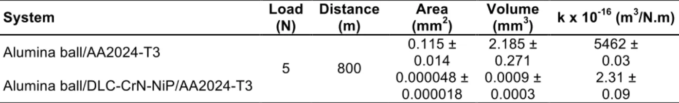
Table 2. Results from the tribological tests.
System Load (N) Distance (m) (mmArea 2) Volume (mm3) k x 10-16 (m3/N.m) Alumina ball/AA2024-T3 0.115 ± 0.014 2.185 ± 0.271 5462 ± 0.03 Alumina ball/DLC-CrN-NiP/AA2024-T3 5 800 0.000048 ± 0.000018 0.0009 ± 0.0003 2.31 ± 0.09
As it can be observed, the wear constant value, k, for the uncoated aluminum alloy against the counterpart of 5.46 ± 0.00003 x 10⁻¹³ m3/N.m is approximately 2400 times greater that for the coated system, which is equal to 2.31 ±0.00003 x 10⁻¹⁶ m3/N.m. These values have the same order of magnitude as those reported by Stallard et
al. [13], who obtained a sliding wear rate of 5.1 x 10⁻¹⁶ m3/N.m for the same DLC coating against WC balls as counterpart.
However, it is interesting to compare these values with those reported by Bolleli et al. [5], who carried out tribological tests under similar contact conditions (alumina ball of 6 mm and 5 N normal load) of DLC coatings deposited onto an AA6068-T6 substrate, using a WC-CoCr thermal sprayed coating of 125 µm in thicknes as intermediate layer. The number of cycles corresponding to the wear test was of 10 x 107, at a sliding velocity of 0.3 m/s, which is 6 times higher than the sliding velocity employed in the present work. Nevertheless, the friction coefficient reported was of 0.1 and the wear rate was of order of 10-16 m3/N.m, values which are consistent with those obtained in the present work and with those reported in the pertinent literature for the a-C:H films, sliding against various different counterparts [5]. The low friction coefficient and the wear response were attributed to the formation of the microcrystalline graphite-like wear debris that could stick to the mating surface. This fact was corroborated by Raman laser spectroscopy. These authors considered that this phenomena occurred as consequence of large flash temperatures at the contact points between the tribopairs and used the equation proposed by Ashby et al. [20] for evaluating this temperature, which resulted in a value of
∆T ~
300oC.On the other hand, since the flash temperature is directly proportional to the sliding velocity and in the present research this parameter is almost 6 times smaller, the value of ∆T will be of approximately 50oC. As indicated by Bhushan [21], when studying the influence of sliding velocity and load on the wear of DLC coatings, this temperature rise is not sufficient to produce a phase transition process whereby a low shear strength graphite-like layer is formed at the sliding interface.
3.2 SEM morphology of the wear scars
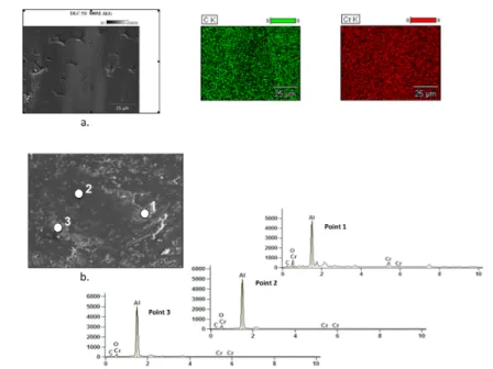
The typical wear scar morphologies are shown in Figure 3 for the DLC/CrN/NiP/AA2024-T3 substrate as well as the alumina counterpart.
Figure 3. SEM micrograph of the wear scars: a. on the Al2024-T3 sample coated with DLC/CrC/NiP with the corresponding mapping of Cr and C; b. Alumina ball and the EDS analysis related to the points indicated in
micrograph, showing the composition of the adhered material. (Normal load = 5 N, sliding velocity = 0.1 m/s and 43 x 106 cycles)
As expected, the surface of the DLC coated system in the middle of the wear scar shows the typical nodular morphology, i.e., the cauliflower characteristic structure (Figure 3a) of the intermediate electroless layer of a higher thickness. The darker zone in the micrographs corresponds to the coating that has been worn out in a smaller amount, indicating that an uneven wear took place in contact with the alumina ball. This fact could be verified by the element mapping shown in the same Figure, where it is observed that in some regions of the wear scar the C distribution is not uniform.
Nevertheless, the Cr distribution is uniform all over the scar, which coupled with the fact that the friction coefficient value at the end of the test was of 0.1, indicates the preservation of the coating integrity, i.e. its existence, although as a very thin film, but without the presence of any surface failures.
Furthermore, the chemical analysis by EDS carried out to evaluate the morphology of the wear scar of the alumina counterpart used in this test indicated, as expected, the presence of some traces of carbon, chromium and oxygen at point 1 shown in this figure. These results demonstrate that the coating adhered to the aluminum ball as a consequence of the difference in the hardness values between the tribopairs. The presence of Cr is considered to be due to the existence of a small quantity of Cr in the coating, as a result of the manufacturing process, as it was mentioned previously.
3. CONCLUSIONS
The results indicate that, under the present testing conditions, the duplex coating of NiP/CrC-DLC deposited onto a AA2024-T3 substrate exhibits a satisfactory behavior from the mechanical stability point of view, when the thickness of the NiP layer is higher than 60 µm, since no surface failures were observed at the end of the tests. In this way, the results of the analytical calculation of the elastic contact deformation fields under a spherical indenter, for the case of Hertzian contact employing the software Elastica©, have been verified. It was found that for the coated system, the magnitude of the friction coefficient was of approximately 0.1 and that
of the wear rate was of about 2.31 ± 0.09 x 10⁻¹⁶ m3/N.m. On the contrary, for the uncoated substrate, the friction coefficient was of approximately 0.5 and the wear rate of 5.46 x 10⁻¹³ m3/N.m, that is to say, 3 orders of magnitude greater than that determined for the coated system.
4. ACKNOWLEDGEMENTS
Professor Staia acknowledges the financial support form Universidad Central de Venezuela and Arts et Métiers Paris Tech, (ENSAM Lille), France. Professor Puchi-Cabrera gratefully acknowledges the financial support of the Conseil Régional Nord-Pas de Calais, France, through the International Chair program 2011. The authors thank J. Fuentes for carrying out the wear tests in CENMACOR-UCV (Venezuela).
5. REFERENCES
[1] B.J. Jones,A. Mahendran, A.W. Anson, A.J. Reynolds, R. Bulpett, J. Franks Diamond-like carbon coating of alternative metal alloys for medical and surgical applications, Diamond and Related Materials 19, 685, 2010. [2] Ali Merati, RTO-AG-AVT-140- Chapter 24 – Materials Replacement For Aging Aircraft, Science and Technology Organization, NATO, 24-1 a 24-18, 2010.
[3] S.J. Bull, Tribology of carbon coatings:,DLC, diamond and beyond, Diamond and Related Materials, 4, 827-836, 1995.
[4] Nie, X., Wilson, A., Leyland, A., Matthews, A., Deposition of duplex Al2O3/DLC coatings on Al alloys for tribological applications using a combined micro-arc oxidation and plasma-immersion ion implantation technique, Surf. Coat. Technol., 121, 506–513, 2000.
[5] Bolelli G., Bonferroni B., Coletta G., Lusvarghi L., Pitacco F., Wear and corrosion behaviour of HVOF WC– CoCr/CVD DLC hybrid coating systems deposited onto aluminium substrate, Surf. Coat. Technol.,205, 4211– 4220, 2011.
[6] Wanstrand O., Larsson M., Kassman-Rudolphi A˚, Mechanical and tribological properties of vapour deposited low friction coatings on Ni plated substrates, Tribology International, 33, 737–742, 2000.
[7] Cruz R., Rao J., Rose T., Lawson K., Nicholls J.R., DLC–ceramic multilayers for automotive applications Diamond & Related Materials, 15, 2055 – 2060, 2006.
[8] Lifang X., Zhaohui Y., Jiaxuan l., Effects of intermediate layers on the tribological behavior of DLC coated 2024 aluminum alloy, Wear, 257, 599–605, 2004.
[9] Liao, J.X., Xia, L.F., Sun, M.R., Liu, W.M., Xue, Q.J.: The tribological properties of a gradient layer prepared by plasma- based ion implantation on 2024 aluminum alloy. Surf. Coat. Technol., 183, 157–164, 2004.
[10] Wang L, Wan S., Wang S.C., Wood R. J. K., Xue Q. J., Gradient DLC-Based Nanocomposite Coatings as a Solution to Improve Tribological Performance of Aluminum Alloy, Tribol Lett ,38:155–160, 2010.
[11] Moreno, E.T, Santana, Y.Y, Cabrera-Puchi, E. S, Staia, M.H., Evaluación de la Capacidad de Soporte de Carga de Recubrimientos Duros Depositados sobre la Aleación de Aluminio 7075-T6. Revista de Metalurgia, Vol. 43, 464-473, 2007.
[12] Puchi-Cabrera E.S., Staia M.H., Ochoa-Pérez E.A., Teer D.G., Santana-Méndez Y.Y., La Barbera-Sosa J.G., Chicot D., Lesage J., Fatigue behavior of a 316L stainless steel coated with a DLC film deposited by PVD magnetron sputtering ion plating, Materials Science and Engineering A527, 498–508, 2010.
[13] Jarratt M., Stallard J., Renevier N.M., Teer D.G., An improved diamond-like carbon coating with exceptional wear properties, Diamond and Related Materials 12, 1003–1007,2003.
[14] Abdullah S, Beden S. M., Ariffin A. K., Fatigue Crack Growth Simulation of Aluminum Alloy under Cyclic Sequence Effects, Aluminium Alloys, Theory and Applications, INTEC Open, ed. Tibor Kvackaj, ISBN 978-953-307-244-9, 247, 2011.
[14] Tsui T.Y., Joo Y-C., A new technique to measure through film thickness fracture toughness. Thin Solid Films, 401, 203-210, 2001.
[15] Gan Z., Zhang Y., Yu G., Ta C.M., Lau S.P., Intrinsic mechanical properties of diamond-like carbon films deposited by filtered cathodic vacuum arc Journal of Applied Physics, 94, 3509-3515, 2004.
[16] Ronkainen H, Koskinen J., Varjus S, Holmberg K, Load-carrying capacity evaluation of coating/substrate systems for hydrogen-free and hydrogenated diamond-like carbon films, Tribology Letters 6, 63–73, 1999. [17] Bemporad E, Sebastiani M., Staia M.H., Puchi Cabrera E., Tribological studies on PVD/HVOF duplex coatings on Ti6Al4V substrate, Surface & Coatings Technology, 203, 566–571, 2008.
[18] Psyllakia P.P., Jeandin M., Pantelisc D.I., M. Allouard, Pin-on-disc testing of PE-CVD diamond-like carbon coatings on tool steel substrates, Surf. Coat. Technol.,130, 297-303, 2000.
[19] Ronkainen H., Varjus S, Koskinen J., Holmberg K, Differentiating the tribological performance of hydrogenated and hydrogen-free DLC coatings, Wear 249, 260–266, 2001.
[20] M. F. Ashby, J. Abulawi, H.S. Kong,Temperature Maps for Frictional Heating in Dry Sliding, Tribology Transactions 34, 577-587, 1991.
[21] Nanotribology, Nanomechanics and Materials Characterization, Bhushan Ed., Nanotechnology, 2-nd Edition, Springer Science, 819-820, 2007.