HAL Id: tel-02932456
https://tel.archives-ouvertes.fr/tel-02932456
Submitted on 7 Sep 2020HAL is a multi-disciplinary open access
archive for the deposit and dissemination of sci-entific research documents, whether they are pub-lished or not. The documents may come from teaching and research institutions in France or abroad, or from public or private research centers.
L’archive ouverte pluridisciplinaire HAL, est destinée au dépôt et à la diffusion de documents scientifiques de niveau recherche, publiés ou non, émanant des établissements d’enseignement et de recherche français ou étrangers, des laboratoires publics ou privés.
Design of high-speed robots with drastically reduced
energy consumption
Rafael Balderas Hill
To cite this version:
Rafael Balderas Hill. Design of high-speed robots with drastically reduced energy consumption. Au-tomatic. École centrale de Nantes, 2019. English. �NNT : 2019ECDN0028�. �tel-02932456�
T
HESE DE DOCTORAT DE
L'ÉCOLE
CENTRALE
DE
NANTES
COMUE UNIVERSITE BRETAGNE LOIRE
ECOLE DOCTORALE N°601
Mathématiques et Sciences et Technologies de l'Information et de la Communication
Spécialité : Automatique, productique et robotique
Conception des robots rapides à consommation énergétique
drastiquement réduite
Thèse présentée et soutenue à Nantes, le 25 Septembre 2019
Unité de recherche : Laboratoire des Sciences du Numérique de Nantes (LS2N)
Par
Rafael BALDERAS HILL
Rapporteurs avant soutenance :
Nicolas Andreff Professeur des universités, Université de Franche-Comté – FEMTO-ST Belhassen Chedli Bouzgarrou Maître de conférences, HDR, Sigma-Clermont – Institut Pascal
Composition du Jury :
Président : Nicolas Mansard Directeur de recherche, LAAS – CNRS
Examinateurs : Christine Chevallereau Directrice de recherche, LS2N – CNRS
Viviane Pasqui Maître de conférences, HDR, ISIR – GEMA
Directeur de thèse : Sébastien Briot Chargé de recherche, HDR, LS2N – CNRS
Co-encadrants de thèse : Abdelhamid Chriette Maître de conférences, LS2N – ECN Philippe Martinet Directeur de recherche, CHORALE – INRIA
Abstract
It is well-known that one of the most representative future challenges in industrial robotics, is to increase the energy efficiency of robot manipulators. In industrial applications, such as high-speed pick-and-place operations, the accuracy is typically the most important criteria to measure the robot performance. Nevertheless, the design trends to operate at high speeds are shifting to the design of robots, which are not only accurate, but also they can perform in an energy-efficient way. When performing high-speed motions in pick-and-place robots, a significant amount of energy is required to move and stop the robot in the desired positions. This mainly occurs when achieving a desired high speed since a large amount of energy must be brought to make the robot move, and then this energy is dissipated to stop the robot in the braking phase. This is not efficient at all. It would be smarter to store the energy.
This thesis proposes an actuation principle for reducing the energy consumption of high-speed robots by placing variable stiffness springs (VSS) in parallel to the motors that actuate the links of a high-speed robot. The main idea is to smartly tune online the force/displacement relation of the VSS, associated to the VSS stiffness, so that the robot is put in near a resonance mode, thus considerably decreasing the energy consumption during fast pseudo-periodic pick-and-place motions. By adding a spring with controllable stiffness in parallel to the robot actuated links, two performances are achieved: i) direct power connection between the motor and the robot links, thus ensuring accuracy at high-speeds; ii) control of the stored potential energy to be released per cycle of the pick-and-place motion, thus exploiting the robot natural dynamics at high-speeds, and therefore reducing the energy consumption.
The experimental results of the suggested approach on an industrial-sized prototype show the drastic reduction of energy consumption for fast quasi-periodic pick-and-place-like motions.
Finally, we extend the concept of exploiting the natural dynamics for robots in other applications in which they are not necessarily required to perform high-speed tasks, but in which a continuous exchange from potential to kinetic energy may be smartly exploited.
Keywords: high-speed pick-and-place robots, variable stiffness springs, exploiting the natural dynamics, exchange from potential to kinetic energy, reduction of the energy consumption.
R´
esum´
e
Il est bien connu qu’un des plus importants d´efis de la robotique industrielle est d’augmenter l’efficacit´e ´energ´etique des robots manipulateurs. Dans les applications industrielles, telles que les op´erations de prise et d´epose `a grande vitesse, la pr´ecision est g´en´eralement le crit`ere le plus important pour mesurer les performances du robot. Cependant, les m´ethodes de conception des robots rapides ont ´evolu´e vers la conception des robots, pas seulement pr´ecis, mais ´egalement performants sur le plan ´energ´etique. Lorsque des robots de prise et d´epose effectuent des mouvements `a grande vitesse, une quantit´e importante d’´energie est n´ecessaire pour d´eplacer et arrˆeter le robot dans les positions souhait´ees. Cela se produit principalement lorsque la vitesse ´elev´ee souhait´ee est atteinte, car une grande quantit´e d’´energie doit ˆetre apport´ee pour faire bouger le robot, puis cette ´energie est dissip´ee pour arrˆeter le robot en phase de freinage. Ce n’est pas efficace du tout. Il serait plus pertinent d’avoir un stockage d’´energie.
Cette th`ese propose un principe d’actionnement pour r´eduire la consommation d’´energie des robots `a grande vitesse en pla¸cant des ressorts `a raideur variable en parall`ele des actionneurs d’un robot rapide. L’id´ee est de r´egler la raideur de ces ressorts `a l’aide d’autres actionneurs afin de mettre le robot `a proximit´e de modes de r´esonance lors de son d´eplacement (les trajectoires de prise et d´epose ´etant pseudo-oscillantes). En ajoutant un ressort `a raideur variable en parall`ele des liaisons actionn´ees par le robot, deux per-formances sont obtenues: i) la connexion directe entre les liaisons du moteur et du robot, garantissant ainsi la pr´ecision `a grande vitesse, et ii) le contrˆole de l’´energie potentielle stock´ee `a lib´erer par cycle du mouvement de prise et d´epose, exploitant ainsi la dynamique naturelle du robot `a haute vitesse et r´eduisant la consommation d’´energie.
Les r´esultats exp´erimentaux de l’approche sugg´er´ee sur un prototype de taille indus-trielle montrent la r´eduction drastique de la consommation d’´energie pour des mouvements rapides pseudo-oscillants.
Finalement, nous ´etendons le concept d’exploitation de la dynamique naturelle des robots dans d’autres applications dans lesquelles ils n’ex´ecutent pas forcement des tˆaches `
a grandes vitesses, mais dans lesquelles un ´echange continu d’´energie potentielle `a ´energie cin´etique peut ˆetre exploit´e intelligemment.
Mots-cl´es: robots rapides de prise et d´epose, ressort `a raideur variable, exploiter la dynamique naturelle, ´echange entre ´energie potentielle et ´energie cin´etique, r´eduction de la consommation d’´energie.
Acknowledgements
Before beginning this manuscript, I would like to express some words to the people who have guided me, shared time with me, and supported me during the past three years.
Firstly, I would like to express my great appreciation to my thesis director, S´ebastien Briot for his valuable and constructive guidance during the planning and development of this thesis. With his useful critiques and comprehensive experience on dynamics, he has been a great mentor throughout this journey. I am extremely grateful for the balance he has put between guiding me and encouraging me to be autonomous during this research. I would like to thank my co-supervisors, Abdhelhamid Chriette and Philippe Martinet, for the time they have shared with me, their patience and their wise advises provided for the development of this work and during the editing of the research articles.
I would like to express my gratitude also to St´ephane Jolivet, David Llevat and Philippe Lemoine for their patience to help me to build and to implement the proto-type for the experimental validations. Their combined advises helped me to improve the different parts of the prototype, including the mechanics and electronics.
I also would like to express my gratitude to my thesis defense committee and especially to Profs. Nicolas Andreff and Chedli Bouzgarrou. Their detailed and valuable comments have contributed to the quality of this manuscript.
My PhD life would not have been the same without my friends. I address a partic-ular acknowledgement to my friend Saman Lessanibahri who is finishing his PhD thesis as well. We have spent very good moments together since the Master. I would like to also address special thanks to my friends and colleagues David, Marl`ene, S´ebastien, Jo-han, Victor, Emmanuel, Susana, Tahir, Zhongmou, Julian, Franco, Guillaume, Minglei, Cathe, Antoine, Elias, Erick, Elaheh, Jing, for having interesting discussions and sharing beautiful moments with me.
I would like to express a special thank to the Mexican Council of Science and Tech-nology (CONACYT) for sponsoring my PhD studies, their support was very important during these three years of PhD studies.
I would like to express all my gratitude and love to my parents Arturo and Mercedes, and to my brothers Arturo and Juan, who have always encouraged me to accomplish my
objectives and most importantly to wisely advise me during all my life. I am eternally grateful to them for their love, education and never ending support.
And finally, last but by no means least, I would like to express my tremendous grat-itude and my love to my girlfriend Stephanie. I am not sure that this thesis would have concluded successfully without her comprehension, patience and love.
To my parents, Arturo and Mercedes To the woman I love, Stephanie To the memory of my grandparents, Josefina and Armando.
Table of Contents
Abstract i R´esum´e iii Acknowledgements v Table of Contents ix List of Figures xv List of Tables xxv Nomenclature xxix Introduction 11 State of the art 5
1.1 Historical evolution of high-speed robots . . . 6
1.1.1 Origins . . . 6
1.1.2 Towards achieving more speed for robots in industrial applications . 11 1.2 Towards designing energy-efficient high-speed robots . . . 18
1.2.1 Conventional techniques for energy minimization . . . 19
1.2.1.1 Beginnings with static balancing techniques . . . 19
1.2.1.2 Design of lightweight robot architectures . . . 21
1.2.1.3 Motion planning techniques . . . 24
1.2.1.4 Redesign of electric cabinets . . . 27
1.2.1.5 Use of elastic passive compliance: SEAs and VSAs . . . . 29
1.2.2 Increasing the energy efficiency of pick-and-place robots: use of springs . . . 35 1.3 Existing strategies for increasing the energy efficiency of high-speed robots 41
1.4 Summary . . . 42
2 Dynamic and power consumption modeling of an energy-efficient high-speed robot 45 2.1 Actuation concept based on parallel variable stiffness springs . . . 46
2.1.1 Architecture description of variable stiffness springs . . . 47
2.1.2 Resonance aspects of springs in parallel to motors: Case study with 1-DOF robot . . . 50
2.2 Dynamic analysis of the parallel configuration of variable stiffness springs with the actuated links of parallel robots . . . 54
2.2.1 Dynamic modeling of parallel robots . . . 54
2.2.1.1 Dynamic model of tree-loop robots . . . 54
2.2.1.2 Dynamic model of parallel robots . . . 56
2.2.2 Dynamic modeling of variable stiffness springs . . . 57
2.3 Energy consumption modeling . . . 59
2.3.1 Working principle of motor drive system . . . 59
2.3.2 Modeling of the motor drive system . . . 60
2.3.3 Operation modes . . . 64
2.3.4 Model of energetic losses . . . 66
2.4 Simulation of physical models and identification of preponderant energetic losses . . . 69
2.5 Summary . . . 74
3 Exploiting robot natural motions in order to reduce the energy con-sumption 77 3.1 Performing energy-efficient pick-and-place motions in the case of known dynamic parameters . . . 78
3.1.1 Matching pick-and-place boundary conditions with the robot free-response . . . 78
3.1.1.1 Solution of boundary value problems by using the shooting method . . . 81
3.1.1.2 BVP applied on energy-efficient high-speed robots . . . 83
3.1.2 Application of the energy-efficient motion generator to a five-bar mechanism with VSS: for constant and variable payload . . . 89
3.1.2.1 First set of boundary pick-and-place constraints: for
con-stant and variable payload . . . 90
3.1.2.2 Second set of boundary pick-and-place constraints: for constant and variable payload . . . 96
3.1.3 Application of the energy-efficient motion generator to a Delta robot with VSS: for constant and variable payload . . . 99
3.1.3.1 First set of boundary pick-and-place constraints: for con-stant and variable payload . . . 100
3.1.3.2 Second set of boundary pick-and-place constraints: for constant and variable payload . . . 105
3.2 Performing energy-efficient pick-and-place motions in the case of unper-fectly known dynamic parameters . . . 110
3.2.1 Online solution of boundary value problem . . . 111
3.2.2 Adaptive feedback linearization . . . 113
3.2.3 Application of the online motion generator to a five-bar mechanism with VSS . . . 117
3.2.3.1 Case without adaptive law and unperfectly known param-eters . . . 117
3.2.3.2 Case with adaptive law . . . 118
3.3 Summary . . . 122
4 Prototype and experimental validations 125 4.1 Description of the prototype . . . 126
4.1.1 CAD modeling and prototyping of robot and variable stiffness system126 4.1.2 Technical description of robot revolute joints and variable stiffness joints . . . 131
4.1.3 Instrumentation and communication . . . 133
4.2 Identification of dynamic parameters . . . 136
4.2.1 Identification procedure based on Least Squares method . . . 136
4.2.2 Identified dynamic parameters of the robot and the variable stiffness system . . . 139
4.3 Experimental results for reducing energy consumption . . . 145
4.3.1 Controller design . . . 145
4.3.3 Results . . . 149
4.3.3.1 First set of boundary pick-and-place constraints . . . 149
4.3.3.2 Second set of boundary pick-and-place constraints . . . 155
4.4 Summary . . . 161
5 Exploiting natural dynamics: other application cases 165 5.1 Definition of application cases . . . 166
5.2 Reducing the energy consumption of an omnidirectional spherical rolling robot . . . 167
5.2.1 Description of spherical rolling robot with mobile masses . . . 168
5.2.2 Modeling of spherical rolling robot with mobile masses . . . 169
5.2.2.1 Geometric Model . . . 170
5.2.2.2 First Order Kinematic Model . . . 171
5.2.2.3 Second Order Kinematic Model . . . 171
5.2.2.4 Dynamic Model . . . 172
5.2.3 Modeling of variable stiffness springs in parallel configuration with the mobile masses . . . 173
5.2.3.1 Rolling Robot with VSS in Parallel . . . 173
5.2.4 Energy-efficient motion generation and control . . . 174
5.2.4.1 Motion generation for spherical rolling robot . . . 175
5.2.4.2 Variable stiffness joint trajectories from VSS placed in par-allel . . . 177
5.2.4.3 Optimization problem formulation: cost function and de-cision variables . . . 179
5.2.5 Simulation results . . . 180
5.2.5.1 SolidWorks model . . . 180
5.2.5.2 ADAMS Model . . . 181
5.2.5.3 Model Properties and Parameters . . . 181
5.2.5.4 Simulations . . . 182
5.3 Increasing the feasible static-wrench workspace of robots . . . 186
5.3.1 Exploiting natural oscillations for enlarging feasible static-wrench workspace . . . 188
5.3.1.1 Shooting method applied on robot manipulators with heavy payloads . . . 188
5.3.1.2 Initial oscillations for achieving optimal aspect-connecting velocity . . . 189 5.3.2 Case study: 2-DOF serial robot . . . 190 5.4 Summary . . . 197
Conclusion 199
A Dynamic model of the five-bar mechanism 207 B Dynamic model of the 3-DOF Delta robot 209 C Equations and joints specifications of the variable stiffness system 211 D Dynamic model of the 2R serial robot with payload 215 E List of publications of presented works 217
List of Figures
1.1 Unimate robot (first industrial robot) [Malone 2011]. . . 6
1.2 Unimate robot in production lines of General motors [Malone 2011]. . . 7
1.3 Expansion of industrial robots from 1950 to 1970. . . 8
1.4 Expansion of industrial robots from 1970 to 1980. . . 9
1.5 Two main inventions towards the designing of faster robots. On the left a SCARA robot is shown, and on the right the first direct-driven robot is presented. . . 11
1.6 AdeptOne SCARA robot [Adept]. . . 11
1.7 Schematic of patent of Delta robot by Reymond Clavel [Clavel 1990]. . . . 12
1.8 Applications of Delta robots. . . 13
1.9 Examples of high-speed robots. . . 16
1.10 Examples of high-speed robots (continued). . . 17
1.11 Examples of static balanced mechanisms. . . 20
1.12 Delta robot with the balancing mechanism [Baradat 2008]. . . 21
1.13 Anthropomorphic lightweight robot for high-speed safe interaction [Kim 2017]. 22 1.14 High-speed CDPR FALCON-7 [Kawamura 2000]. . . 24
1.15 Power consumption with method proposed in [Riazi 2016]. . . 25
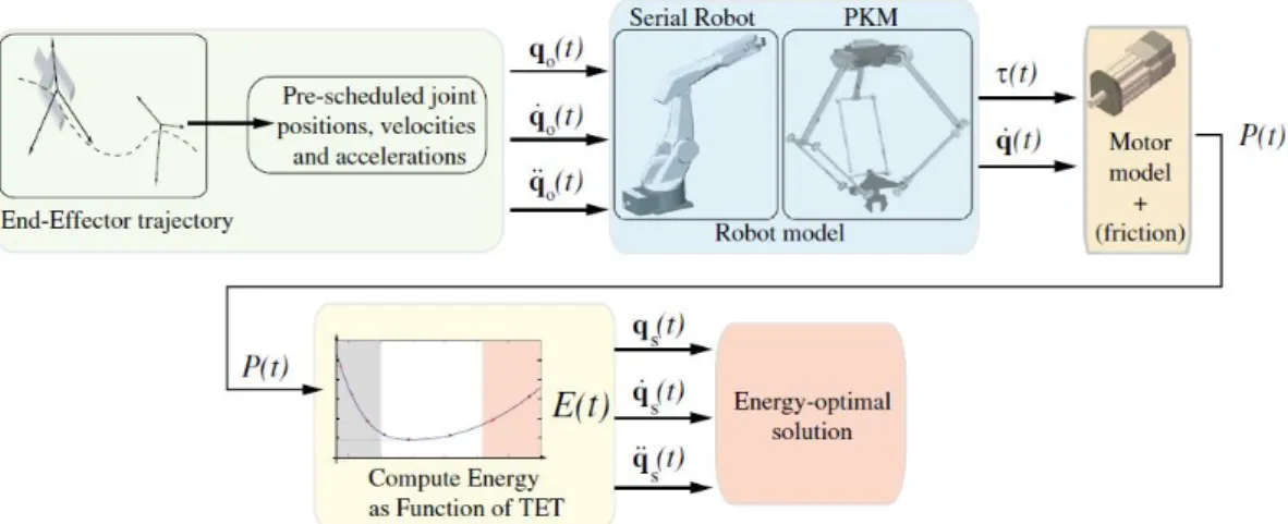
1.16 Block diagram proposed for the time scaling strategy to minimize the en-ergy consumption (TET stands for Task Execution Time). [Pellicciari 2013]. 26 1.17 DC-based power architecture [Pellicciari 2015]. . . 28
1.18 Classical AC power system [Pellicciari 2015]. . . 28
1.19 Schematic of SEA . . . 30
1.20 Examples of SEAs applied on applications related to absorbing impacts and increase peak power (walking robots) and for human-interaction for increasing safety. . . 31
1.21 Schematic of variable stiffness actuator. . . 32
1.22 Examples of designs by following the port-based modeling approach pre-sented in [Visser 2010]. . . 33
1.23 Actuator with Adjustable Stiffness (AwAS) developed by IIT from the
VIACTORS project. . . 34
1.24 Schematic of constant stiffness spring in parallel to the motor. . . 36
1.25 Examples of robots with constant stiffness springs in parallel [Barreto 2016]. 37 1.26 Slow serial manipulator with VSS in parallel [Goya 2012]. . . 39
2.1 On the left, a 2R serial robot with variable stiffness linear springs in parallel arrangement with the links is shown. On the right the same 2R serial robot with variable stiffness torsional springs is presented (the grey circles denote the actuated joints). . . 47
2.2 On the left, a five-bar mechanism with variable stiffness linear springs in parallel arrangement with the actuated links is shown. On the right the same parallel robot with variable stiffness torsional springs is presented (the grey circles denote the actuated joints). . . 47
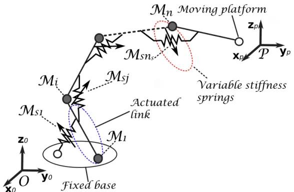
2.3 A general serial robot with variable stiffness linear springs in parallel con-figuration with the links. . . 48
2.4 A general serial robot with variable stiffness torsional springs in parallel configuration with the links. . . 48
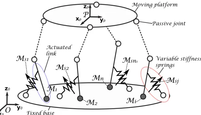
2.5 A general parallel robot with variable stiffness linear springs in parallel configuration with the actuated links. . . 49
2.6 A general parallel robot with variable stiffness torsional springs in parallel configuration with the actuated links. . . 49
2.7 one-degree-of-freedom robot with torsional spring of constant k in parallel. 51 2.8 one-degree-of-freedom robot with VSS in parallel. . . 53
2.9 Virtual tree structure . . . 55
2.10 Power transmission system of variable stiffness springs in parallel to the motors. qai and qsj represent the parallel robot joints and variable stiffness joints coordinates, respectively, and i = 1, ..., n, j = 1, ..., ns. . . 58
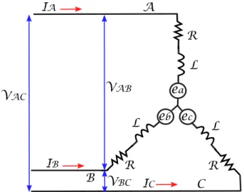
2.11 Schematic of three-phase brushless motor drive system . . . 61
2.12 Electric circuit of the brushless motor with three phases . . . 61
2.13 Electromotive forces [Chapman 1991] . . . 62
2.14 Motor scheme with load attached to the rotor. . . 64
2.15 Motoring mode . . . 65
2.16 Freewheeling motoring mode . . . 66
2.18 Freewheeling generating mode . . . 67 2.19 Five-bar mechanism parameterization with two actuated joints q11 and q21
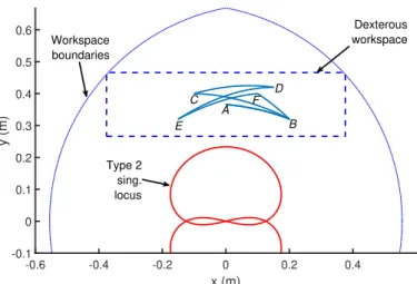
located at A11 and A21, respectively, and three passive joints q12, q22 and q13 located at A12, A22 and A13, respectively. . . 70 2.20 Multiple-point pick-and-place sequence in the five-bar mechanism workspace:
A → B (travel time: 0.27 s), B → C (travel time: 0.23 s), C → D (travel time: 0.21 s), D → E (travel time: 0.3 s), E → F (travel time: 0.29 s), F → B (travel time: 0.25 s), B → A (travel time: 0.18 s). . . 72 2.21 Input torque for the first joint of the parallel robot for nominal actuation. . 73 2.22 Input torque for the second joint of the parallel robot for nominal actuation. 73 2.23 Energetic losses for the nominal actuation, i.e. the losses from the two
motors in the active joints q11 and q21 of the five-bar mechanism. . . 74 2.24 Energy losses decoupled from the energetic model in order to show how
preponderant is each loss when performing a nominal high-speed pick-and-place operation. . . 74 3.1 Decomposition of a video taken from real a pick-and-place application in
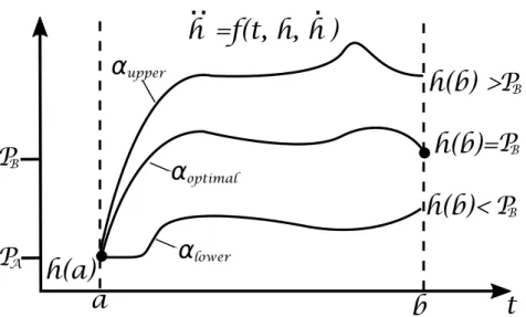
the bread industry. The desired pick-and-place positions are represented by PA, PB, PC, PD, PE and PF. The time connecting these desired positions are defined according to the following sequence: PA → PB (travel time: ≈ 0.3 s), PB → PC (travel time: ≈ 0.1 s), PC → PD (travel time: ≈ 0.27 s), PD → PE (travel time: ≈ 0.23 s), PE → PF (travel time: ≈ 0.3 s). The red dot represents the end-effector position [Kawasaki robotics]. . . 79 3.2 Graphical interpretation of classic solution of shooting method for a BVP. 82 3.3 Graphical interpretation of shooting method for solving the BVP for the
robot-plus-VSS system. . . 85 3.4 Five-bar mechanism parameterization with two actuated joints q11 and q21,
and three passive joints q12, q22 and q13. The variable stiffness torsional springs are located in parallel to the two actuated joints defined by qs1 and qs2. . . 91 3.5 Multiple-point pick-and-place sequence in the five-bar mechanism workspace:
A → B (travel time: 0.2 s), B → C (travel time: 0.4 s), C → D (travel time: 0.4 s), D → E (travel time: 0.2 s), E → F (travel time: 0.4 s). The pick-and-place points are connected through the trajectories generated from the shooting method. . . 93
3.6 Input torques for the first joint of the parallel robot for the two cases: Nom-inal fifth-degree polynomial and variable stiffness with trajectories from BVP with constant payload. . . 93 3.7 Input torques for the second joint of the parallel robot for the two cases:
Nominal fifth-degree polynomial and variable stiffness with trajectories from BVP with constant payload. . . 94 3.8 Input torques from the joints that actuate the variable stiffness joints from
the VSS for the task with constant payload. . . 94 3.9 Energetic losses for the two cases compared: Nominal fifth-degree
polyno-mial and variable stiffness with trajectories from BVP with constant payload. 94 3.10 Input torques for the first joint of the parallel robot for the two cases:
Nom-inal fifth-degree polynomial and variable stiffness with trajectories from BVP with variable payload. . . 95 3.11 Input torques for the second joint of the parallel robot for the two cases:
Nominal fifth-degree polynomial and variable stiffness with trajectories from BVP with variable payload. . . 95 3.12 Input torques from the joints that actuate the variable stiffness joints from
the VSS for the task with variable payload. . . 96 3.13 Energetic losses for the two cases compared: Nominal fifth-degree
polyno-mial and variable stiffness with trajectories from BVP with variable payload. 96 3.14 Multiple-point pick-and-place sequence in the five-bar mechanism workspace:
A → B (travel time: 0.2 s), B → C (travel time: 0.4 s), C → D (travel time: 0.2 s), D → E (travel time: 0.4 s), E → F (travel time: 0.2 s). The pick-and-place points are connected through the trajectories generated from the shooting method. . . 97 3.15 Energetic losses for the two cases compared: Nominal fifth-degree
polyno-mial and variable stiffness with trajectories from BVP with constant payload. 98 3.16 Energetic losses for the two cases compared: Nominal fifth-degree
polyno-mial and variable stiffness with trajectories from BVP with variable payload. 99 3.17 Delta robot parameterization with three actuated joints q1, q2 and q3. The
variable stiffness torsional springs are located in parallel to the three actu-ated joints defined by qs1, qs2 and qs3. . . 100
3.18 Pick-and-place sequence in the workspace of the Delta robot: G → H (travel time: 0.12 s), H → I (travel time: 0.06 s), I → J (travel time: 0.14 s), J → K (travel time: 0.08 s), K → L (travel time: 0.11 s). The pick-and-place points are connected through the trajectories generated from the shooting method. . . 101 3.19 Pick-and-place sequence for the Delta robot in the three planes: G → H
(travel time: 0.12 s), H → I (travel time: 0.06 s), I → J (travel time: 0.14 s), J → K (travel time: 0.08 s), K → L (travel time: 0.11 s). The pick-and-place points are connected through the trajectories generated from the shooting method. . . 102 3.20 Input torques for the first joint of the Delta robot for the two cases:
Nom-inal fifth-degree polynomial and variable stiffness with trajectories from BVP for the first set of pick-and-place conditions and for a constant payload.103 3.21 Input torques for the second joint of the Delta robot for the two cases:
Nom-inal fifth-degree polynomial and variable stiffness with trajectories from BVP for the first set of pick-and-place conditions and for a constant payload.103 3.22 Input torques for the third joint of the Delta robot for the two cases:
Nom-inal fifth-degree polynomial and variable stiffness with trajectories from BVP for the first set of pick-and-place conditions and for a constant payload.104 3.23 Energetic losses for the two cases compared: Nominal fifth-degree
polyno-mial and variable stiffness with trajectories from BVP on the Delta robot for the first set of pick-and-place conditions and for a constant payload. . . 104 3.24 Energetic losses for the two cases compared: Nominal fifth-degree
polyno-mial and variable stiffness with trajectories from BVP on the Delta robot for the first set of pick-and-place conditions and for a variable payload. . . 105 3.25 Pick-and-place sequence for the Delta robot: G → H (travel time: 0.12 s),
H → I (travel time: 0.06 s), I → J (travel time: 0.1 s), J → K (travel time: 0.06 s), K → L (travel time: 0.1 s), L → M (travel time: 0.08 s). The pick-and-place points are connected through the trajectories generated from the shooting method. . . 106
3.26 Pick-and-place sequence for the Delta robot in the three planes: G → H (travel time: 0.12 s), H → I (travel time: 0.06 s), I → J (travel time: 0.1 s), J → K (travel time: 0.06 s), K → L (travel time: 0.1 s), L → M (travel time: 0.08 s). The pick-and-place points are connected through the trajectories generated from the shooting method. . . 107 3.27 Input torques for the first joint of the Delta robot for the two cases:
Nom-inal fifth-degree polynomial and variable stiffness with trajectories from BVP for the second set of pick-and-place conditions and for a constant payload. . . 107 3.28 Input torques for the second joint of the Delta robot for the two cases:
Nom-inal fifth-degree polynomial and variable stiffness with trajectories from BVP for the second set of pick-and-place conditions and for a constant payload. . . 108 3.29 Input torques for the third joint of the Delta robot for the two cases:
Nom-inal fifth-degree polynomial and variable stiffness with trajectories from BVP for the second set of pick-and-place conditions and for a constant payload. . . 108 3.30 Energetic losses for the two cases compared: Nominal fifth-degree
polyno-mial and variable stiffness with trajectories from BVP on the Delta robot for the second set of pick-and-place conditions and for a constant payload. 108 3.31 Energetic losses for the two cases compared: Nominal fifth-degree
polyno-mial and variable stiffness with trajectories from BVP on the Delta robot for the second set of pick-and-place conditions and for a variable payload. . 109 3.32 Block diagram of online solution of the BVB combined with adaptation
law for dealing with dynamics uncertainties. . . 110 3.33 BVP solved online for generating the desired optimal trajectories within
the control system. . . 113 3.34 Online motion generator, adaptation law and feedback linearization
inte-grated in the complete control scheme. . . 116 3.35 Multiple-point pick-and-place sequence in the five-bar mechanism workspace:
A → B (travel time: 0.3 s), B → C (travel time: 0.4 s), C → D (travel time: 0.3 s), D → E (travel time: 0.4 s), E → F (travel time: 0.25 s). . . . 118 3.36 Energetic losses for the two cases compared: Nominal and by using VSS. . 119 3.37 Adaptation of inertial parameter zz11R. . . 120
3.38 Adaptation of inertial parameter zz21R. . . 121 3.39 Energetic losses for the two cases compared: Nominal and by using VSS. . 121 4.1 CAD of five-bar mechanism. . . 127 4.2 CAD of variable stiffness system. . . 128 4.3 Spring schematic . . . 128 4.4 CAD of five-bar mechanism with VSS in parallel. . . 130 4.5 Real prototype in isometric view. . . 130 4.6 Real prototype in front view. . . 131 4.7 Detailed description of robot active joint and variable stiffness joint. . . 132 4.8 Detailed description of passive joints. . . 132 4.9 Motor drive system [Siemens]. . . 133 4.10 Motor drive system connection diagram [Siemens]. . . 134 4.11 Comparison between measured and calculated input torques from robot
actuated joint 1. . . 143 4.12 Comparison between measured and calculated input torques from robot
actuated joint 2. . . 143 4.13 Comparison between measured and calculated input torques from variable
stiffness system associated to the VSS in parallel to the first actuated link. 144 4.14 Comparison between measured and calculated input torques from variable
stiffness system associated to the VSS in parallel to the second actuated link.144 4.15 Real-time control system for experimental validation with dSPACE
con-troller card. Once the task finished, the data from velocities and input torques are saved from ControlDesk in order to feed the energy consump-tion model from Eq. (2.43). . . 147 4.16 Multiple-point pick-and-place sequence in the five-bar mechanism workspace:
A → B (travel time: 0.32 s), B → C (travel time: 0.31 s), C → D (travel time: 0.30 s), D → E (travel time: 0.31 s), E → B (travel time: 0.34 s), B → A (travel time: 0.31 s). . . 151 4.17 Input torques grouping the first actuation chain considering a nominal case
and the case when using VSS for the first set of boundary pick-and-place constraints. . . 152 4.18 Input torques grouping the second actuation chain considering a nominal
case and the case when using VSS for the first set of boundary pick-and-place constraints. . . 153
4.19 Comparison of energetic losses for two types of actuation: nominal and case when using VSS and considering the friction effects due to the VSS for the first set of boundary pick-and-place constraints. . . 154 4.20 Comparison of energetic losses for two types of actuation: nominal and
case when using VSS and without considering the friction effects due to the VSS for the first set of boundary pick-and-place constraints. . . 155 4.21 Tracking errors along the trajectory generated for the first set of boundary
pick-and-place conditions in order to show that thanks to the direct power connection between the motors and the proximal links of the five-bar robot we can ensure accuracy at high-speeds. . . 155 4.22 Multiple-point pick-and-place sequence in the five-bar mechanism workspace:
A → B (travel time: 0.33 s), B → C (travel time: 0.32 s), C → D (travel time: 0.32 s), D → E (travel time: 0.31 s), E → B (travel time: 0.33 s), B → A (travel time: 0.31 s). . . 157 4.23 Input torques grouping the first actuation chain considering a nominal case
and the case when using VSS for the second set of boundary pick-and-place constraints. . . 158 4.24 Input torques grouping the second actuation chain considering a nominal
case and the case when using VSS for the second set of boundary pick-and-place constraints. . . 158 4.25 Comparison of energetic losses for two types of actuation: nominal and
case when using VSS and considering the friction effects due to the VSS for the second set of boundary pick-and-place constraints. . . 159 4.26 Comparison of energetic losses for two types of actuation: nominal and
case when using VSS and without considering the friction effects due to the VSS for the second set of boundary pick-and-place constraints. . . 160 4.27 Tracking errors along the trajectory generated for the second set of
bound-ary pick-and-place conditions in order to show that thanks to the direct power connection between the motors and the proximal links of the five-bar robot we can ensure accuracy at high-speeds. . . 161 5.1 Reciprocating mass driven rolling robots . . . 169 5.2 Schematic of the rolling robot without elastic elements . . . 169 5.3 Schematic of the rolling robot with VSS . . . 174 5.4 Joint control scheme . . . 177
5.5 CAD models of the rolling robots . . . 181 5.6 ADAMS models of the rolling robots . . . 182 5.7 Trajectories from the four reciprocating masses in order to move the center
of mass of the sphere. . . 184 5.8 Trajectories computed from the optimal motion planner for the spring bases
of the VSS. . . 184 5.9 Forces computed along the masses trajectories without springs. . . 184 5.10 On the left the forces computed along the masses trajectories are shown
when VSS are place in parallel. On the right the forces from adjusting the VSS springs bases are shown. . . 185 5.11 Energy consumed from the two types of actuation. . . 185 5.12 On the left, the graphical interpretation of the disconnection between
as-pects due to actuation limits on a 2R serial robot workspace. A and B represent the boundary conditions which seek to be joined thanks to the BVP. On the right, the kinematic structure of the 2-DOF robot with pay-load is shown. . . 191 5.13 Torques computed from the exciting-plus-BVP trajectory for the case 1. . . 193 5.14 Optimal trajectory for connecting two points by solving the BVP from
boundaries of case 1. A and B represent the boundary conditions of case 1 and they are joined thanks to the solution of the BVP. . . 193 5.15 Torques computed from the exciting-plus-BVP trajectory for the case 2. . . 194 5.16 Optimal trajectory for connecting two points by solving the BVP from
boundaries of case 2. A and B represent the boundary conditions of case 2 and they are joined thanks to the solution of the BVP. . . 194 5.17 Torques computed from the exciting-plus-BVP trajectory for the case 3. . . 195 5.18 Optimal trajectory for connecting two points by solving the BVP from
boundaries of case 3. A and B represent the boundary conditions of case 3 and they are joined thanks to the solution of the BVP. . . 195 5.19 Torques computed from the exciting-plus-BVP trajectory for the case 4. . . 196 5.20 Optimal trajectory for connecting two points by solving the BVP from
boundaries of case 4. A and B represent the boundary conditions of case 4 and they are joined thanks to the solution of the BVP. . . 196
List of Tables
3.1 RMS values of input torques for nominal case and for case when using VSS in parallel (constant payload). . . 92 3.2 RMS values of input torques for nominal case and for case when using VSS
in parallel (variable payload). . . 93 3.3 RMS values of input torques for nominal case and for case when using VSS
in parallel (constant payload). . . 98 3.4 RMS values of input torques for nominal case and for case when using VSS
in parallel (variable payload). . . 98 3.5 RMS values of input torques for nominal case and for case when using VSS
in parallel for the Delta robot for the first set of pick-and-place conditions and for constant payload. . . 102 3.6 RMS values of input torques for nominal case and for case when using VSS
in parallel for the Delta robot for the first set of pick-and-place conditions and for a variable payload. . . 102 3.7 RMS values of input torques for nominal case and for case when using
VSS in parallel for the Delta robot for the second set of pick-and-place conditions and for a constant payload. . . 106 3.8 RMS values of input torques for nominal case and for case when using
VSS in parallel for the Delta robot for the second set of pick-and-place conditions and for a variable payload. . . 109 3.9 RMS values of input torques for nominal case and for case when using VSS
in parallel without using the adaptation law. . . 119 3.10 RMS values of input torques for nominal case and for case when using VSS
in parallel by considering adaptation of the inertial parameters. . . 120 4.1 Spring specifications . . . 129 4.2 Inertial dynamic parameters from CAD model. . . 137
4.3 RMS values of input torques for nominal case and for case when using VSS in parallel for the first set of boundary pick-and-place conditions consider-ing the friction effects. . . 153 4.4 RMS values of input torques for nominal case and for case when using VSS
in parallel for the first set of boundary pick-and-place conditions without considering the friction effects. . . 153 4.5 RMS values of input torques for nominal case and for case when using VSS
in parallel for the first set of boundary pick-and-place conditions consider-ing the friction effects and by analyzconsider-ing the distribution of torques for the actuation with VSS. . . 154 4.6 RMS values of input torques for nominal case and for case when using VSS
in parallel for the first set of boundary pick-and-place conditions without considering the friction effects and by analyzing the distribution of torques for the actuation with VSS. . . 154 4.7 RMS values of input torques for nominal case and for case when using
VSS in parallel for the second set of boundary pick-and-place conditions considering the friction effects. . . 159 4.8 RMS values of input torques for nominal case and for case when using VSS
in parallel for the second set of boundary pick-and-place conditions without considering the friction effects. . . 159 4.9 RMS values of input torques for nominal case and for case when using
VSS in parallel for the second set of boundary pick-and-place conditions considering the friction effects and by analyzing the distribution of torques for the actuation with VSS. . . 160 4.10 RMS values of input torques for nominal case and for case when using VSS
in parallel for the second set of boundary pick-and-place conditions without considering the friction effects and by analyzing the distribution of torques for the actuation with VSS. . . 160 5.1 Mass properties: ADAMS model . . . 182 5.2 Relevant parameters: ADAMS model . . . 183 5.3 ADAMS Contact Model Parameters . . . 183 5.4 Maximum values of input torques and optimal values for ˙qA from the
C.1 Components of the joints from the variable stiffness system and the five-bar active joints. . . 213
Nomenclature
In this nomenclature, the main variables and abbreviations used in this manuscript are presented. Additionally, it should be noted that the following conventions were used:
vectors and matrices in bold style;
scalar variables and names of points in italic styles; abbreviations of terms in regular style
Symbols
F0(O, x0, y0, z0) global frame Fp(P , xp, yp, zp) platform frame
P represents moving platform
Mi motors that actuate n robot actuated joints Msj motors that actuate ns variable stiffness joints
lOA distance from point O to point A qa vector of robot active joints
qs vector of variable stiffness joints associated to the VSS
t time
x vector of platform pose
β amplitude of periodic trajectory
ω angular velocity
f frequency
zz moment of inertia
m mass of a rigid body
g gravity vector
A parallel kinematic Jacobian matrix B serial kinematic Jacobian matrix
Lt Lagrangian of the virtual tree structure Lp Lagrangian of the platform
τta vector of virtual input efforts wp wrench of the platform τ vector of robot input efforts λ vector of Lagrange multipliers M matrix of inertia
c vector of Coriolis, centrifugal and gravitational effects fa vector grouping the active joint friction terms
τs vector of force/displacement relation associated to the VSS coupled to the robot in parallel
K stiffness matrix grouping the stiffness constants of the springs k Ms matrix of inertia associated to the VSS dynamics
hs vector of Coriolis, centrifugal and gravitational effects fs vector grouping the variable stiffness joint friction terms Pmotor resistive losses due to resistances in the motor phases Pbrake resistive losses due to braking resistance
Pdamp damping losses Pcond conduction losses Pswitch switching losses Prectif ier rectification losses Plosses model of power losses
α slope of a differential equation ˙
τ time differentiation of τ to obtain the robot jerk equations ˙
τvss time differentiation of τvss to obtain VSS jerk equations h differential equation
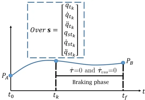
E vector of boundary constraints from BVP s decision variable vector for BVP
zzR regrouped inertial effects in the active joint axes
J1, J2 regrouped inertial effects on the two axes of the VSS joints fs static friction effects associated to the robot active joints fvss static friction effects associated to the variable stiffness system
from the VSS
χ vector of dynamic parameters related to the robot χs vector of dynamic parameters related to the VSS
Ws matrix of VSS configuration variables for identification Kp, Ki, Kd symmetric positive definite matrices
νa, νs auxiliary control inputs
A coordinate system BR C rotation matrix ˆ pi; i = 1, . . . , 4 unit vector J cost function F input force
xDecVar decision variable
Abbreviations
VSS variable stiffness springs VSA variable stiffness actuator DOF degrees-of-freedom
PUMA Programmable Universal Machine for Assembly SCARA Selective Compliance Assembly Robot Arm RMS root means square
SEA series elastic actuator BVP boundary value problem CTC Computed Torques Control LM Levenberg-Marquardt
Introduction
Context of the thesis
During the last decades, robotics research communities and companies have kept special attention on addressing the problem of increasing the energy efficiency of high-speed industrial robots. Typically, the most common tasks for high-speed robots in industrial applications are to pick and place objects in different positions of the robot workspace. For such types of high-speed operations, a significant amount of energy is required to move and stop the robot in the desired positions. This mainly occurs when achieving a desired high speed since a large amount of energy must be brought to make the robot move, and then this energy is dissipated to stop the robot in the braking phase. This is not efficient at all.
The literature review shows that, in order to solve this problem, the conventional techniques developed over the last few years are mainly three (see Chapter 1):
designing lightweight robot architectures, thus permitting the use of less powerful motors;
for slow motions, gravity-balancing techniques have been proposed in order to reduce the input efforts;
classical motion planning techniques for optimizing the robot trajectory and oper-ation.
Even if the aforementioned techniques have shown their effectiveness to increase the energy efficiency, firstly, designing a lightweight robot structure leads to worsen the robot stiffness, affecting the accuracy of the robot. Although gravity-balancing techniques can compensate the input efforts to move slow pick-and-place robots, these techniques cannot be applied for high-speed robots for which the inertial effects are preponderant. Finally, even if classical motion planning techniques have been used to optimize the robot trajec-tory to keep the input torques constrained, these methods do not fully exploit the robot dynamics, leading to lower percentages of energy reduction.
More recently, variable stiffness actuators (VSAs) have been introduced for decreas-ing the energy consumption of pick-and-place robots by smartly stordecreas-ing energy in their springs. Nevertheless, the serial arrangement of springs and motors of the VSAs decreases the accuracy of the robot end-effector due to uncontrolled deflections at high-speeds.
In order to solve this problem and to increase the energy efficiency while ensuring accuracy at high-speeds, this thesis proposes the use of parallel arrangement of variable stiffness springs (VSS) and motors. The idea is to smartly tune online the stiffness of the VSS so that the robot is put in near a resonance mode, thus considerably decreasing the energy consumption during fast quasi-periodic pick-and-place motions. Furthermore, the parallel configuration of VSS and motors ensures the load balancing at high-speed without losing the accuracy of the robot.
Contributions of the thesis
This manuscript presents several major contributions which are listed as follows:
The design of an energy-efficient actuation chain for performing high-speed pick-and-place motions: It appears in Chapter 1 that, in order to reduce the energy consumption of robots, three approaches are developed in most of the cases: i) conventional techniques based on designing lightweight robot architectures, thus allowing the use less powerful motors; ii) generation of classical motion plan-ning techniques that do not fully exploit the robot natural dynamics; iii) the use of variable stiffness springs (VSS), in series and in parallel to the motors, in order to have an energy storage to carry out the reduction of the energy consumption, being this latter the most attractive for seeking to exploit the robot natural dynamics. Despite rather encouraging results, the works done for reducing the energy con-sumption by using springs have drawbacks, such as lack of accuracy when placing VSS in series, lack of energetic analysis due to the fact that the energy consumed by the motors that adjust the VSS are not taken into account, and the fact that they have been only applied for slow robots. For this reason in Chapter 2, we present the actuation concept based on VSS in parallel configuration to the motors, for high-speed robots. This actuation chain is constituted of a variable stiffness spring which is placed in parallel to the actuated joints of a high-speed robot manipulator, which can be either serial or parallel. This means that there is a motor to actuate the robot joint, and there is an additional motor which modifies the equilibrium
position, and thus the stiffness of the VSS placed in parallel. This additional motor controlling the stiffness of the VSS, and thus the exchange from potential to kinetic energy, will allow to exploit the natural dynamics of the robot for fast quasi-periodic motions. Additionally, in Chapter 2, we propose an energy consumption model in order to estimate the energetic losses of the full actuation, i.e. robot-plus-VSS, when performing high-speed tasks, thus considering the energy consumed by the motors that actuate the VSS.
The proposition of a motion generator that exploits the natural dynamics of pick-and-place robots: In Chapter 3, we propose an energy-efficient motion generator that exploits the robot natural motions. This is done by matching the desired pick-and-place motions with the robot free-response. The main idea is to exploit the combined motion of the parallel robot active joints and the variable stiffness joints from the VSS placed in parallel. This is done in order to exploit the force/displacement relation of the VSS associated to the VSS optimal stiffness, so that we minimize the robot and VSS input torques simultaneously, and thus the full actuation chain energy consumption for fast quasi-periodic motions. In addition to that, thanks to the developed energy consumption model, we compare our actuation principle, i.e. robot-plus-VSS, with a nominal type of actuation in which there is no elastic element, and the trajectories are typically defined by polynomial laws. Simulations of the suggested approach on a five-bar mechanism and on a Delta robot are performed and show the drastic reduction of energy consumption.
Experimental proof of the new actuation concept: In addition to the nu-merical simulations, an experimental prototype was designed and commissioned to perform fast quasi-periodic motions in order to validate the theoretical formula-tions. These experimental results are shown in Chapter 4, and demonstrate the successful validation of the new actuation concept to perform fast energy-efficient pseudo-periodic motions, and thus to exploit the natural dynamics of the robot. The experimental results show a considerable increase on the energy efficiency of the robot while performing pick-and-place-like motions.
Extending the concept of exploiting natural dynamics to robots in other applications: One of the advantages of the concept of exploiting the natural dy-namics is that it can be applied for any robot in which an exchange from potential to kinetic energy may appears. That is why in Chapter 5, we present an extension
of this concept of exploiting the natural motions of robots, for robotic systems in other applications: i) for reducing the energy consumption of a mobile robot by using VSS in parallel, and ii) for increasing the feasible static-wrench workspace of robots carrying a payload for which the reachable workspace is usually limited due to the maximal value of the torque that each actuator of the robot joints can deliver.
Let us now start with a bibliographical overview of high-speed robots and a review of existing solutions for energy consumption reduction.
Chapter 1
State of the art
1.1. Historical evolution of high-speed robots p. 6 1.2. Towards designing energy-efficient high-speed robots p. 18 1.3. Existing strategies for increasing the energy efficiency of high-speed robots p. 41
1.3. Summary p. 42
This Chapter is dedicated to present a review on the historical evolu-tion of industrial robots, emphasizing their use for high-speed industrial operations, such as pick-and-place tasks. First of all, a bibliographical review on the well-known architectures for performing high-speed tasks in industrial applications, is presented.
On the second part of this Chapter, a review on some already avail-able solutions, such as lightweight robots or classical motion planning techniques, for increasing the energy efficiency of robot manipulators will be presented. The efficiency of such robots is shown and their ad-vantages and drawbacks are discussed. Additionally, we will recall some preceding works on passive compliant actuation, which is a recently in-troduced type of actuation for reducing the energy consumption of pick-and-place robots, and from which this thesis is motivated. We will thus firstly introduce the so-called variable stiffness actuators (VSAs), which is a type of compliant actuation based on serial arrangement of springs and motors, and finally on a second stage we will present a bibliograph-ical review of the actuation concept based on parallel elastic actuation. Finally, it is proposed to use a new actuation concept for high-speed robots based on variable stiffness springs (VSS) in parallel to the mo-tors, for increasing the energy efficiency at high-speeds. The VSS are used as energy storage for carrying ot the reduction of the energy con-sumption and their parallel configuration with the motors ensure the load balancing at high speed without losing the accuracy of the robot.
1.1
Historical evolution of high-speed robots
In this Section, we propose to make a brief review of the evolution of industrial robots, emphasizing their importance for high-speed applications. The most significant milestones of the history of industrial high-speed robots are mentioned, combined with a description of the most representative robots designed in the last decades. It is worth noticing that we do not make an exhaustive list of all existing high-speed robots, but rather to give key points in the development of these robotic systems.
1.1.1
Origins
In order to talk about high-speed robots, it is firstly necessary to make a brief overview of the beginnings of industrial robots. The idea of designing and prototyping robots for industrial applications dates back to the 1950’s with the beginning of Industrial Robotics [Gasparetto 2019]. Nevertheless, some inventions in automation took place before, e.g. a programmable paint-sprayer device in 1938 [Koetsier 2019], or a teleoperated manipulator invented by Goertz in 1949. There are several works dealing with the true origins of indus-trial robotics, such as [Ceccarelli 2001][Ceccarelli 2004][Siciliano 2008][Gasparetto 2016]. However, the history of industrial robots is typically set in the 1950’s with the inventor George Devol, who designed in 1954 a Programmable Article Transfer [Devol 1954]. Such device was the basis for designing and prototyping the Unimate robot (Fig. 1.1), which is considered the first true industrial robot in history [Malone 2011]. The Unimate robot, which was hydraulically actuated, was used for first time in a production line of General Motors for transporting die castings from an assembly line (Fig.1.2).
Figure 1.2: Unimate robot in production lines of General motors [Malone 2011].
After this breakthrough towards the development of industrial robots, several robot manufacturing companies appeared with the objective of building such types of machines. One of the first companies that emerged for getting involved on the designing of industrial robots was AMF Corporation. For instance, in 1962 the first cylindrical robot called Versatran was designed and manufactured by this company [Birnie 1974]. The robot Versatran was used in the production lines of Ford in Ohio USA and in some production companies of Japan (See Fig. 1.3a).
The expansion of industrial robots in Europe took place in the 1960’s with the company Svenska Metallverken in Sweden, which implemented Unimate robots for very first tasks involving pick-and-place tasks [Westerlund 2000]. Years later, in Norway, the first painting robot was manufactured by the Trallfa Company [IFR] (Fig. 1.3b). It is worth mentioning that the appearance of robots allowed to automatize other important production tasks such as welding. Unimation was the first company to manufacture welding robots, while General Motors was the first company to install this kind of systems in their automotive plants, in 1969. Years after, FIAT installed the first welding robot in Europe at their plants in Turin (Italy) [IFR] (See Fig. 1.3d). For a non-exhaustive list of the existing industrial robots from 1950 to 1970, the reader can refer to the list of figures stacked in Fig. 1.3.
(a) The first cylindrical robot, the Versatran from AMF Corpo-ration in 1962 [Birnie 1974].
(b) First commercial painting robot in 1969 [IFR].
(c) First production line with hy-draulic actuated robots at Daimler Benz, Sindelfingen by KUKA in 1971 [IFR].
(d) First production line of welding robots in Europe in 1972 [IFR]. Figure 1.3: Expansion of industrial robots from 1950 to 1970.
As it can be seen from the aforementioned generation of industrial robots, between 1954 and 1970, most of the prototypes of industrial robots were mainly actuated by means of hydraulic actuators. The shifting from hydraulic to electric actuators took place in 1970 with the developments of electronic components and microprocessors. This change to electric motors allowed to implement control systems able to deal with more complex and computationally expensive tasks, thus approaching to an era of industrial robots which could react fast enough to perform faster industrial operations.
(a) Vicarm/Stanford arm at Vicarm Inc, USA in 1973 [Scheinman 1973].
(b) The first fully electric robot, IRB 6 from ASEA in 1974 [IFR].
(c) ABB developed an industrial robot with a payload up to 60 kg in 1975 [IFR].
(d) PUMA was developed by Uni-mation/Vicarm; USA, with sup-port from General Motors in 1978 [Gasparetto 2019].
Figure 1.4: Expansion of industrial robots from 1970 to 1980.
Continuing with the evolution of industrial robots and with the shifting from hy-draulic to electric actuation, in 1973 Prof. Scheinman developed the famous Stanford Arm (Fig. 1.4a) [Scheinman 1973]. This prototype was the first six-degree-of-freedom robot actuated by six electric motors and controlled by six microprocessors. It had five revolute joints and one prismatic joint designed by a combination of harmonic drives and gearbox composed of spur gears.
was designed by ASEA (now ABB) [IFR]. This industrial robot was called IRB6 and it had an anthropomorphic design as it can be seen in Fig. 1.4b. The arm of this robot mimicked the arm of a human, and it had a payload of 6 kg, with five DOF. It was used in industrial applications to polish stainless steel tubes [IFR]. A year after, in order to meet with the demands of the automotive industry of having more payload, ABB developed an industrial robot with a payload up to 60 kg called IRB60 (Fig. 1.4c). It was first used by the company Saab in Sweden for welding car assemblies [IFR]. Continuing with the evolution of robots actuated by electric motors, in 1978 Unimation/Vicarm with support of General Motors, developed the well-known Programmable Universal Machine for Assembly (PUMA) weighted less than five pounds and able to perform tasks involving handling small parts in production lines (Fig. 1.4d) [Gasparetto 2019].
Towards the designing of faster robots, in 1978 the Japanese scientist Hiroshi Makino developed the SCARA-robot (Selective Compliance Assembly Robot Arm), which was made of three revolute joints with parallel axis and a prismatic joint placed at the end of the kinematic chain (Fig. 1.5a) [Makino 1980]. Its structure lightness allowed to imple-ment faster controllers allowing to speed-up tasks such as the assembly of small objects. Another relevant invention towards the designing of faster robots was the appearance of direct drive actuated robots. The first prototype implementing direct drive actuators was the CMU Direct Drive Arm [Asada 1983]. It is shown in Fig. 1.5b and it was developed by Kanade and Asaka at Carnegie Mellon University. This robot could perform tasks with high accuracy and faster operational speeds due to the fact that there was no need of intermediate gears or chain systems for the transmission system.
Finally, in 1984, what is considered the first commercially industrial high-speed robot was developed by AdeptOne (See Fig. 1.6), combining the SCARA-based design and the use of direct drive actuators [Gasparetto 2019]. From this time in history of industrial robotics, the career towards the design of high-speed robots started by creating new kinematic structures, implementing faster controllers, designing new transmission systems, etc.
These scientific and technical inventions allowed to use robots in other applications different from the automotive industry, such as in the electronics, food and pharmaceutical sectors. Additionally, it is worth mentioning that SCARA robots were included in the assembly lines in the Japanese industries. This impulses Japan to become in the 1980’s, not only the leader on robot manufacturing, but also in the production of electronic components [Adept].
(a) First prototype of SCARA robot [Makino 1980].
(b) The first prototype of direct-driven robot [Asada 1983]. Figure 1.5: Two main inventions towards the designing of faster robots. On the left a SCARA robot is shown, and on the right the first direct-driven robot is presented.
Figure 1.6: AdeptOne SCARA robot [Adept].
1.1.2
Towards achieving more speed for robots in industrial
ap-plications
The great advances on electric-driven robots due to the development of faster processors, servo controllers and direct-drive motors, allowed to take industrial robots from the 1990’s to nowadays to another level of operational speeds.
The need of robots that could perform high-speeds attract the attention of several industrial sectors due to the possibility of increasing their productivity, and thus their
Figure 1.7: Schematic of patent of Delta robot by Reymond Clavel [Clavel 1990].
economical incomes. That is why between the end of the 1980’s and the beginnings of the 1990’s, the scientific research communities were pushed to design innovative kinematic structures capable of performing high-speed industrial operations. It was then that the idea of implementing parallel kinematic chains instead of the classical serial chain took relevance within the research communities. This is due to the fact that a parallel kine-matic chain could lead to a type of lightweight robot capable of performing high speeds. Additionally, in terms of accuracy, the parallel robots divide the load among their several legs of the system, allowing to create more rigid mechanisms.
Thus, by following this boom on the developing of kinematic architectures that could perform faster operational speeds, in 1986 the Swiss scientist Reymond Clavel conceived the so-called Delta robot [Clavel 1990]. This parallel mechanism had three translational DOFs and one rotational DOF (See. Fig. 1.7). This parallel robot was a breakthrough towards the design of several high-speed parallel manipulators, devoted mainly for pick-and-place operations.
In Fig. 1.7, the schematic of the patent of the Delta robot from Prof. Clavel is shown. The main idea of its conception is the use of parallelograms, from which three articulated arms are connected. The three parallelograms restrict completely the orientation of the platform which remains with only three translational DOFs. The actuators are mounted
(a) Delta robots packaging pretzels [Bonev 2001].
(b) The Flex-Picker robot from ABB [Pierrot 1999].
Figure 1.8: Applications of Delta robots.
on the base and the links are made from a low-weighted material allowing for the mobile platform to achieve accelerations up to 50 G in experimental environments and 12 G in industrial applications [Clavel 1990]. This makes the Delta robot an ideal mechanism for performing pick-and-place operations.
The first application of a Delta-like robot in a commercial-industrial sector was in 1992 by the company Demaurex, which had six Delta robots operating in a robotized work-cell for loading pretzels into trays [Bonev 2001] (See Fig. 1.8a). Later in 1998, ABB developed the Flex-Picker robot (Fig. 1.8b), which is based on a Delta kinematic structure and it was considered the fastest pick-and-place robot in the world [Pierrot 1999]. It is an industrial version of the Delta robot with 4-DOF, and can produce accelerations and velocities above 10 G and 10 m/s, respectively. The cycle period can be below to 0.4 s.
The appealing characteristics in terms of operational speeds that parallel manipula-tors had brought to industrial applications, such as pick-and-place tasks, attracted the attention of several researchers and companies. That is why from the 1998 to nowadays, they started to design and build new mechanisms based on parallel structures in order to operate at high speeds. Among several examples of high-speed pick-and-place robots, we can list non-exhaustively:
prototypes were presented within the development of a new family of 4-DOF high-speed parallel manipulators at LIRMM [Pierrot 1999][Pierrot 2009][Pierrot 2001]. The first prototype for validating this family of high-speed robots was equipped with rotatory drives, and it achieved accelerations higher than 5 G.
the double SCARA robot (Fig. 1.9c): It is one of the most popular 4-DOF mecha-nism, together with the Flex-Picker robot. It can perform pick-and-place tasks with a precision of 0.005 mm in a workspace of 150 mm x 105 mm. It can perform tasks with pick-and-place cycles below to 0.5 s;
the Par4 (future Quattro) (Fig. 1.9d): It is based on an architecture of a Delta robot, but it has four legs instead of three. It is a 4-DOF dedicated to pick-and-place operations. It can reach accelerations up to 13 G with pick-and-pick-and-place cycle times below to 0.25 s;
the Heli4 (Fig. 1.9e): It is a 4-DOF parallel robot, inspired from a Delta architecture, but overcoming its limitations by using an articulated traveling plate. It has a symmetrical design with accelerations above 100 m/s2 and velocity of 10 m/s. The moving parts are made from carbon fiber materials.
the X4 robot (Fig. 1.9f): It is a 4-DOF high-speed robot developed in the University of Tsinghua. It can achieve accelerations of the order of 120 m/s2 and velocities of 8 m/s. The repeatability of this robot is of 0.2 mm, and can carry payload up to 4 kg in cycle times of 0.8 s.
the Veloce robot (Fig. 1.10a): It is 4-DOF high-speed parallel robot developed at LIRMM. It is mainly designed for high-speed pick-and-place operations. It consists of four kinematic chains and 4-DOF, from which 3 are independent translation degrees in the three dimensions, and 1 rotational degree around the vertical axis. It is able to reach 10 m/s of maximum velocity and accelerations of 200 m/s2, with a payload up to 10 kg.
the Ragnar (Fig. 1.10b): It is 4-DOF high-speed robot producing three translational and one rotational motion. The payload of this robot is 3 kg, with maximum accelerations of 10 G with pick-and-place cycles of 0.5 s. This robot is an industrial robot typically dedicated for food handling industry [Bai 2016].
the Schoenflies Motion Generator (SMG Fig. 1.10c): It was designed at the McGill University by the Prof. Angeles [Angeles 2006]. It has three translation degrees of freedom and one rotational motion. It can perform pick-and-place operations of 0.5 s of cycle period;
the IRSBot-2 prototype (Fig. 1.10d): It is a 2-DOF translational robot able to reach 20 G of acceleration with repeatability lower than 30 microns in its operational workspace. In addition to that the parallelogram configuration of its proximal links increases the intrinsic stiffness of the architecture. As compared to the Par2 robot, the only spatial architecture robot with 2-translational DOF found in the literature, the IRSBot-2 is simpler, and therefore less subject to uncontrolled parasitic effects, and has a larger workspace, since it has only two legs.
the Par2 (Fig. 1.10e): It is a 2-DOF robot for high-speed pick-and-place operations. It is based on the Quattro robot and it has the following characteristics. All the elements of the distal parts of the legs are only subject to traction/compression effects. This leads to a lighter structure with better acceleration capacities. The authors successfully built a prototype that can reach 53 G. However, even if its acceleration capacities are impressive, its accuracy is poor.
(a) H4 robot with symmetrical design [Pierrot 2001].
(b) H4 robot with asymmetri-cal design [Pierrot 2001].
(c) SCARA robot from Mit-subishi [MitMit-subishi].
(d) the Quattro from Adept [Nabat 2005].
(e) Heli4 prototype
[Nabat 2007]. (f ) X4 prototype [Mo 2017].
(a) Veloce prototype
[Penta Robotics 2004]. (b) Ragnar robot [Bai 2016].
(c) the SMG from McGill University [Angeles 2006].
(d) IRSbot-2 from IRCCYN (LS2N) [Germain 2013].
(e) Par2 robot [Company 2011].
To summarize this Section, it can be seen that most of the developments of robots for performing industrial applications, such as pick-and-place operations, since the 1990’s, have been with the objectives of designing not only accurate robots, but also robots that can operate at high speeds.
In the recent decades, nonetheless, the design trends to operate at high-speeds have shifted to the design of robots that in addition to be fast, they could perform as energy-efficient as possible [Brossog 2015]. The motivations to do that rely on the environmental impacts of processing a robot, which includes the motors and the drivers with their respective energetic losses, the materials for manufacturing the robot links, chassis and joints, electrical cabinet, etc.
The literature review shows that there are two main directions from which the envi-ronmental impacts of an industrial robot may be reduced [Carabin 2017]:
Decrease of the electrical consumption:
– By re-designing the robot architecture, the electrical cabinet, etc; – Motion planning;
– New types of actuators;
Decrease of the use of impacting materials – Lightweight robots;
– Design by using materials with low environmental impacts.
In this thesis, we will concentrate on decreasing the environmental impact by following the direction of reducing the electrical consumption of high-speed robots. In what follows, in Section 1.2, we will thus perform a short review on the conventional techniques for minimizing the energy consumption of robots. The most significant achievements in terms of percentages of energy reduction will be mentioned, combined with a brief description of the most representative techniques for energy minimization.
1.2
Towards designing energy-efficient high-speed
robots
In order to improve the energy efficiency of high-speed robots, researchers from differ-ent disciplines have come up with several strategies which can involve control-based
![Figure 1.7: Schematic of patent of Delta robot by Reymond Clavel [Clavel 1990].](https://thumb-eu.123doks.com/thumbv2/123doknet/7893252.264312/47.892.274.586.177.520/figure-schematic-patent-delta-robot-reymond-clavel-clavel.webp)
![Figure 1.17: DC-based power architecture [Pellicciari 2015].](https://thumb-eu.123doks.com/thumbv2/123doknet/7893252.264312/63.892.244.615.173.434/figure-dc-based-power-architecture-pellicciari.webp)
![Figure 1.26: Slow serial manipulator with VSS in parallel [Goya 2012].](https://thumb-eu.123doks.com/thumbv2/123doknet/7893252.264312/74.892.262.673.168.449/figure-slow-serial-manipulator-vss-parallel-goya.webp)