HAL Id: inria-00439171
https://hal.inria.fr/inria-00439171
Submitted on 6 Dec 2009
HAL is a multi-disciplinary open access
archive for the deposit and dissemination of
sci-entific research documents, whether they are
pub-lished or not. The documents may come from
teaching and research institutions in France or
abroad, or from public or private research centers.
L’archive ouverte pluridisciplinaire HAL, est
destinée au dépôt et à la diffusion de documents
scientifiques de niveau recherche, publiés ou non,
émanant des établissements d’enseignement et de
recherche français ou étrangers, des laboratoires
publics ou privés.
Manal El Dick, Esther Pacitti
To cite this version:
Manal El Dick, Esther Pacitti. Content Distribution in P2P Systems. [Research Report] RR-7138,
INRIA. 2009. �inria-00439171�
a p p o r t
d e r e c h e r c h e
ISRN
INRIA/RR--7138--FR+ENG
Thème COM
Content Distribution in P2P Systems
Manal El Dick — Esther Pacitti
N° 7138
Manal El Dick
†, Esther Pacitti
‡Th`eme COM — Syst`emes communicants ´
Equipe-Projet Atlas
Rapport de recherche n° 7138 — D´ecembre 2009 — 63 pages
Abstract: The report provides a literature review of the state-of-the-art for content distribution. The report’s contributions are of threefold. First, it gives more insight into traditional Content Distribution Networks (CDN), their re-quirements and open issues. Second, it discusses Peer-to-Peer (P2P) systems as a cheap and scalable alternative for CDN and extracts their design challenges. Finally, it evaluates the existing P2P systems dedicated for content distribution according to the identified requirements and challenges.
Key-words: CDN, P2P, content distribution
∗Work partially funded by the DataRing project of the french ANR. †INRIA et LINA, Universit´e de Nantes
R´esum´e : Dans ce rapport, nous dressons un ´etat de l’art des syst`emes de distribution de contenu. Nous apportons trois contributions principales. En premier lieu, nous donnons un aper¸cu global sur les r´eseaux de distribution de contenu, leurs exigences et leurs probl`emes. En second lieu, nous ´etudions les syst`emes P2P en tant qu’alternative efficace aux CDNs et nous identifions leurs d´efis. Enfin, nous ´evaluons les syst`emes P2P existants qui sont con¸cus pour la distribution de contenu.
1
Introduction
The explosive growth of the Internet has triggered the conception of massive scale applications involving large numbers of users in the order of thousands or millions. According to recent statistics [37], the world had 1.5 billion Internet users by the end of 2007. The client-server model is often not adequate for applications of such scale given its centralized aspect. Under this model, a content provider typically refers to a centralized web-server that exclusively serves its content (e.g., pages) to interested clients. Eventually, the web-server suffers congestion and bottleneck due to the increasing demands on its content [96]. This substantially decreases the service quality provided by the web-server. In other terms, the web-server gets overwhelmed with traffic due to a sudden spike in its content popularity. As a result, the website becomes temporarily unavailable or its clients experience high delays mainly due to long download times, which leaves them in frustration. That is why the World Wide Web is often pejoratively called World Wide Wait [58].
In order to improve the Internet service quality, a new technology has emerged that efficiently delivers the web content to large audiences. It is called Content Distribution Network or Content Delivery Network (CDN) [5]. A commercial CDN like Akamai1is a network of dedicated servers that are strategically spread across the Internet and that cooperate to deliver content to end-users. A con-tent provider like Google and CNN can sign up with a CDN so that its concon-tent is deployed over the servers of the CDN. Then, the requests for the deployed content are transparently redirected to and handled by the CDN on behalf of the origin servers. As a result, CDNs decrease the workload on the web-servers, reduce bandwidth costs, and keep the user-perceived latency low. In short, CDNs strike a balance between the costs incurred on content providers and the QoS provided to the users [63]. CDNs have became a huge market for generating large revenues [36] since they provide content providers with the highly required scalabiliy, reliability and performance. However, CDN services are quite expensive, often out of reach for small enterprises or non-profit orga-nizations.
The new web trend, Web 2.0, has brought greater collaboration among Inter-net users and encouraged them to actively contribute to the Web. Peer-to-Peer (P2P) networking is one of the fundamental underlying technologies of the new world of Web 2.0. In a P2P system, each node, called a peer, is client and server at the same time – using the resources of other peers, and offering other peers its own resources. As such, the P2P model is designed to achieve self-scalability : as more peers join the system, they contribute to the aggregate resources of the P2P network. P2P systems that deal with content sharing (e.g., sharing files or web documents) can be seen as a form of CDN, where peers share content and deliver it on each other’s behalf [80]. The more popular the content (e.g., file or web-page), the more available it becomes as more peers download it and eventually provide it for others. Thus, the P2P model stands in direct contrast to traditional CDNs like Akamai when handling increasing amounts of users and demands. Whereas a CDN must invest more in its infrastructure by adding servers, new users bring their own resources into a P2P system. This implies that P2P systems are a perfect match for building cheap and scalable CDN
infrastructures. However, making use of P2P self-scalability is not a straight-forward endeavor because designing an efficient P2P system is very challenging. This report reviews the state-of-the-art for both traditional and P2P content distribution in order to identify the shortcomings and highlight the challenges. Roadmap. The rest of the report is organized as follows. Section2 gives more insight into traditional CDNs and highlights their requirements which are needed for the design of novel and cheaper alternatives. Section 3 presents P2P systems and identifies their fundamental design requirements. Section 4 investigates the recent P2P trends that are useful for content distribution and identifies their challenges. Then, Section 5 deeply explores the state-of-art in P2P solutions for content distribution. It evaluates the existing approaches against the previously identifed requirements (for both P2P and CDN) and enlightens open issues.
2
Insights on Content Distribution Netwoks
Content distribution networks is an important web caching application. First, let us briefly review the different web caching techniques in order to position and understand the CDN technology. Then, we shed lights on CDNs, their requirements and their open issues.
2.1
Background on Web Caching
A web cache is a disk storage of predefined size that is reserved for content requested from the Internet (such as HTML pages and images)2. After an
original request for an object has been successfully fulfilled, and that object has been stored in the cache, further requests for this object results in returning it from the cache rather than the original location. The cache content is temporary as the objects are dynamically cached and discarded according to predefined policies (further details in Section 2.2.1).
Web caching is widely acknowledged as providing three major advantages [6]. First, it reduces the bandwidth consumption since fewer requests and responses need to go over the network. Second, it reduces the load on the web-server which handles fewer requests. Third, it reduces the user-perceived latency since a cached request is satisfied from the web cache (which is closer to the client) instead of the origin web-server. Together, these advantages make the web less expensive and better performing.
Web caching can be implemented at various locations using proxy servers [96, 58]. A proxy server acts as an intermediary for requests from clients to web-servers. It is commonly used to cache web-pages from other web-servers and thus intercepts requests to see if it can fulfill them itself. A proxy server can be placed in the user’s local computer as part of its web browser or at various points between the user and the web-servers. Commonly, proxy caching refers to the latter schemes that involve dedicated servers out on the network while the user’s local proxy cache is rather known as browser cache.
2Web caching is different from traditional caching in main memory that aims at limiting
Figure 1: Web caching: different placements of proxy servers.
Depending on their placement and their usage purpose, we distinguish two kinds of proxies, forward proxies and reverse proxies. They are illustrated in Figure 1.
A forward proxy is used as a gateway between an organisation (i.e., a group of clients) and the Internet. It makes requests on behalf of the clients of the organisation. Then, it caches requested objects to serve subsequent requests coming from other clients of the organisation. Large corporations and Internet Service Providers (ISP) often set up forward proxies on their firewalls to reduce their bandwidth costs by filtering out repeated requests. As illustrated in Figure 1, the university of Nantes has deployed a forward proxy that interacts with the Internet on behalf of the university users and handles their queries.
A reverse proxy is used in a network in front of web-servers. It is dele-gated the authority to operate on behalf of these web-servers, while working in close cooperation with them. Typically, all requests addressed to one of the web-servers are routed through the proxy server which tries to serve them via caching. Figure 1 shows a reverse proxy that acts on behalf of the web-servers of wikipedia.com, cnn.com and youtube.com by handling their received queries. A CDN deploys reverse proxies throughout the Internet and sells caching to websites that aim for larger audience and lower workload. The reverse proxies of a CDN are commonly known as surrogate survers.
2.2
Overview of CDN
A CDN deploys hundreds of surrogate servers around the globe, according to complex algorithms that take into account the workload pattern and the network topology [65]. Figure 2 gives an overview of a CDN that distributes and delivers the content of a web-server in the US.
Figure 2: Overview of a CDN.
Examples of commercial CDNs are Akamai 3 and Digital Island 4. They
mainly focus on distributing static content (e.g., static HTML pages, images, documents, audio and video files), dynamic content (e.g., HTML or XML pages that are generated on the fly based on user specification) and streaming audio or video. Further, ongoing research aims at extending CDN technology to support video on demand (VoD) and live streaming. In this paper, we mainly focus on static content. This type of content has a low frequency of change and can be easily cached; its freshness can be maintained via traditional caching policies [96].
A CDN stores the content of different web-servers and therefore handles related queries on behalf of these web-servers. Each website selects specific or popular content and pushes it to the CDN. Clients requesting this content are then redirected to their closest surrogate server via DNS redirection or URL rewriting. The CDN manages the replication and/or caching of the content among its surrogate servers. These techniques are explained in more detail below.
The interaction between a user and a CDN takes place in a transparent manner, as if it is done with the intended origin web-server. Let us consider a typical user interaction with the well-known CDN, Akamai [91], which mainly deals with objects embedded in a web-page (e.g., images, scripts, audio and video files). First, the user’s browser sends a request for a web-page to the website. In response, the website returns the appropriate HTML page as usual, the only difference being that the URLs of the embedded objects in the page have been modified to point to the Akamai network. As a result, the browser
3http://www.akamai.com
next requests and obtains the embedded objects from an optimal surrogate server.
How is this transparent interaction achieved from a technical perspective? In the following, we investigate this issue by exploring CDN techniques for replication and caching on one hand, and location and routing on the other hand.
Figure 3: Typical user interaction with a website using Akamai services [91].
2.2.1 Replication and Caching in CDN
According to [14] and [87], replication involves creating and permanently main-taining duplicate copies of content on different nodes to improve content avail-ability. One the other hand, caching consists in temporarily storing passing by request responses (e.g., web-pages, embedded objects like images) in order to reduce the response time and network bandwidth consumption on future, equivalent requests. Note that web documents are typically accessed in read-only mode: requests read a document without changing its contents.
Replication. In a CDN, replication is typically initiated when the origin web-servers pushes content to any surrogate web-servers [63, 5]. The surrogate web-servers then manage the replication of the content among each other, either on-demand or beforehand.
In on-demand replication, the surrogate server that has received a query and experienced a cache miss, pulls the requested content from the origin web-server or other surrogate web-servers. In the latter case, it might use a centralized or distributed index to find a nearby copy of the requested content within the CDN.
Beforehand replication implies different strategies that replicate objects a priori and dynamically adjust their placement in a way that brings them closer to the clients and balances the load among surrogate servers [65].
However, due to replication requirements in terms of cost and time, any replicas’ placement should be static for a large amount of time.
Caching. Given that popularity of objects may fluctuate with time, some replicas may become redundant and unnecessary. This leads to unoptimized storage management at surrogate servers. That is why caching can be seen as an interesting alternative to replication, especially in cases where unpredictable numerous users have suddenly interest in the same content.
Content objects are dynamically cached and evicted from the cache according to cache replacement policies. More precisely, each cached object is assigned a cache expiration policy which defines how long it is fresh based on its own characteristics [96]. Upon receiving a request for an object, the server first checks the freshness of its cached version before serving it. In case it has expired, the surrogate server checks with the origin server if the object has changed (by sending a conditional GET (cGET) request, e.g. If-Modified-Since request). Subsequently, the origin server either validates the cached copy or sends back a fresh copy. Since the cache has a limited storage size, the server might need to evict cached objects via one of the cache replacement policies that have been studied in [96]. In the policy LRU, the rarely requested objects stored in the local cache are replaced with the new incoming objects. Additionnaly, the cache may regularly check for expired objects and evict them.
An evaluation of caching and replication as seperate approaches in CDNs is covered in [46], where caching outperforms but replication is still preferred for content availability and reliability of service. If replication and caching cooperate they may greatly fortify the CDN since both deal with the same problem but from a different approach. Indeed, [87] has proved that potential performance improvement is possible in terms of response time and hit ratio if both techniques are used together in a CDN. CDNs may take advantage of the dynamic nature of cache replacement policies while maintaining static replicas for availability and reliability.
2.2.2 Location and Routing in CDN
To serve a query in a CDN, there are two main steps, server location and query routing. The first step defines how to select and locate an appropriate surrogate server holding a replica of the requested object whereas the second step consists in routing the query to the selected surrogate server. In several existing CDNs, these two steps are combined together in a single operation.
A query routing system uses a set of metrics in selecting the surrogate server that can best serve the query. The most common metrics include proximity to the client, bandwidth availability, surrogate load and availability of content. For instance, the distance between the client and a surrogate server can be measured in terms of round-trip-time(RTT) via the common tool of ”ping”.
Actually, each CDN uses its proprietary algorithms and mechanisms for location and routing and does not always reveal all the technology details. Here, we try to give a generic description of the mechanisms commonly used by CDNs, based on the materials in [5, 65]. The most common query routing technique are DNS redirection and URL rewriting.
DNS Redirection. CDNs can perform dynamic request routing using the Internet’s Domain Name System (DNS). The DNS is a distributed directory service for the Internet whose primary role is to map fully qualified domain
names (FQDNs) to IP addresses. For instance, hostname.example.com trans-lates to 208.77.188.166. The DNS distributes the responsibility of assigning domain names and mapping those names to IP addresses over authoritative name servers: an authoritative name server is designated to be responsible for each particular domain, and in turn can designate other authoritative name servers for its sub-domains. This results in a hierarchical authority structure that manages the DNS. To determine an FQDN’s address, a DNS client sends a request to its local DNS server which resolves it by recursively querying a set of authoritative DNS servers. When the local DNS server receives an answer to its request, it sends the result to the DNS client and caches it for future queries. Normally, DNS mapping from an FQDNs to an IP address is static. However, CDNs use modified authoritative DNS servers to dynamically map each FQDN to multiple IP addresses of surrogate servers. The query answer may vary depending on factors such as the locality of the client and the load on the surrogate servers. Typically, the DNS server returns, for a request, several IP addresses of surrogate servers holding replicas of the requested object. The DNS client chooses a server among these. To decide, it may issue pings to the servers and choose based on resulting RTTs. It may also collect historical information from the clients based on previous access to these servers.
URL Rewriting. In this approach, the origin web-server redirects the clients to different surrogate servers by rewriting the URL links in a web-page. For example, with a web-page containing an HTML file and some embedded objects, the web-server would modify references to embedded objects so that they point to the CDN or more particularly to the best surrogate server. Thus, the base HTML page is retrieved from the origin web-server, while embedded objects are retrieved from CDN servers. To automate the rewriting process, CDNs provide special scripts that transparently parse web-page content and replace embedded URLs. URL rewriting can be pro-active or reactive. In the pro-active URL rewriting, the URLs for embedded objects of the main HTML page are formulated before the content is loaded in the origin server. In reactive approach involves rewriting the embedded URLs of a HTML page when the client request reaches the origin server.
2.3
Requirements and Open Issues of CDN
As introduced previously, a CDN has to fulfill stringent requirements which are mainly reliability, performance and scalability [63].
Reliability guarantees that a client can always find and access its de-sirable content. For this, the network should be robust and avoid single point of failure.
Performance mainly involves the response time perceived by end-users submitting queries. Slow response time is the single greatest contributor to clients abandoning web-sites [92].
Scalability refers to the adaptability of the network to handle more amounts of content, users and requests without significant decline in per-formance. For this, the network should prevent bottlenecks due to over-load situations.
The reliability and performance of a CDN is highly affected by the mecha-nisms of content distribution as well as content location and routing. Content distribution defines how the content is distributed over the CDN and made available for clients. It mainly deals with the placement of content and involves caching and replication techniques in order to make the same content accessi-ble from several locations. Thus, with these techniques, the content is located near to the clients yielding low response times and high content availability since many replicas are distributed. Content location and routing defines how to locate the requested content and route requests towards the appropriate and relevant servers. Locality-awareness refers to any topological information about the localities of peers to be able to evaluate their physical proximity. Locality-awareness is a top priority in routing mechanisms in order to find content close to the client in locality.
To expand and scale-up, CDNs need to invest siginficant time and costs in provisioning additional infrastructures [92]. Otherwise, they would compromise the quality of service received by individual clients. Further, they should dy-namically adapt their resource provisioning in order to address unexpected and varying workloads. This inevitably leads to more expensive services for web-sites. In the near future, the clients will also have to pay to receive high quality content (in some of today’s websites like CNN.com, users have already started to pay a subscription to view videos). In this context, scalability will be an issue to deliver high quality content, maintaining low operational costs [5].
Most recently, traditional CDNs [5] have turned towards P2P technology to reduce investments in their own infrastructure, in the context of video stream-ing. The key idea is to dynamically couple traditional CDN distribution with P2P distribution. Basically, the CDN serves a handful of clients which in turn provide the content to other clients. Joost5 and BitTorrent6 are today’s most
representative CDN companies using P2P technology to deliver Internet televi-sion and video streaming, respectively.
To conclude this section, we observe that P2P technology is being progres-sively accepted and adopted as a mean of content distribution. The existing CDNs still depend –at least partly- on a dedicated infrastructure, which re-quires investment and centralized administration. If the CDN could rely on a cheap P2P infrastructure supported only by end-users, this would provide a cheap and scalable alternative that avoids the considerable costs. In the follow-ing, we further investigate the feasibility of pure P2P content distribution.
3
P2P Systems
In the past few years, P2P systems have emerged as a popular way to share con-tent. The most representative systems include Gnutella [30, 42, 41], BitTorrent7 [66] and Fastrack/Kazaa [51]. The popularity of P2P systems is attested by the
5http://www.joost.com
6The technology is called BitTorrent DNA (Delivery Network Accelerator ). Available at
http://www.bittorrent.com/dna/
7
fact that the P2P traffic accounts for more than 70% of the overall Internet traffic according to a recent study8.
The P2P model holds great promise for decentralized collaboration among widespread communities with common interests. This communal collaboration lies at the heart of the Web 2.0 paradigm and stems from the principle of resource sharing. By distributing storage, bandwidth and processing across all participating peers, P2P systems can achieve high scalability, that would otherwise depend on expensive and dedicated infrastructure.
Let us first give an overview of P2P systems by defining their main concepts then we can explore them in more detail.
3.1
Overview of P2P Systems
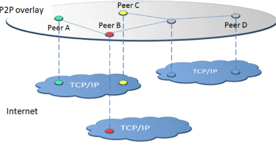
P2P systems operate on application-level networks referred to as overlay net-works or more simply overlays. In other words, peers are connected via a logical overlay network superposed on the existing Internet infrastructure. When two peers are connected via a logical link, this implies that they know each other and can regularly share information across this link. We say that the peers are neighbors in the P2P network. Figure 4 shows a P2P overlay network where Peer A and Peer B are neighbors, independently of their Internet location. A
Figure 4: P2P overlay on top of the Internet infrastructure.
P2P overlay network serves as an infrastructure for applications that wish to exploit P2P features. It relies on a topology and its associated routing protocol. The overlay topology defines how the peers are connected whereas the routing protocol defines how the messages are routed between peers. According to their degree of structure, P2P overlays can be classified into two main categories: structured and unstructured. Typically, they differ on the constraints imposed on how peers are organized and where shared objects are placed [67].
8Available at
http://www.ipoque.com/resources/internet-studies/ internet-study-2008_2009.
The P2P overlay has a direct impact on the performance, reliability and scal-ability of the system. Given that P2P networks operate in open and vulnerable environments, peers are continuously connecting and disconnecting, sometimes unexpectedly failing. The arrival and departure of peers by thousands creates the effect of churn [90] and requires a constant restructuring of the network core. For the purpose of reliability, the P2P overlay must be designed in a way that treats failures and churn as normal occurences. For the purpose of scal-ability, the P2P overlay should dynamically accommodate to growing numbers of participants. The performance of P2P systems refers to their efficiency in locating desirable content, which tightly depends on the P2P overlay, mainly on the routing protocol.
Basically, when a peer searches for a given object, it originates a query and routes it over the P2P overlay. Whenever a peer receives the query, it searches its local repository for the requested object. Eventually, the query reaches a peer that can satisfy the query and respond to the requester. The responder peer is either able to provide a copy of the requested object or has a pointer to the location of the object. Accordingly, the responder peer generates a query response that contains along with the object information (e.g., filename, id), the address of the provider peer. Upon receiving the query response, the query originator downloads a copy of the object from the provider peer.
In the following, we present the two categories of P2P overlays, i.e., unstruc-tured and strucunstruc-tured overlays. For each category, we discuss its behavior under churn as well as its strengths and weaknesses. Then, we summarize by stating the requirements of P2P systems and accordingly compare both categories.
3.2
Unstructured Overlays
Often referred to as the first generation P2P systems, unstructured overlays remain highly popular and widely deployed in today’s Internet. They impose loose constraints on peer neighborhood (i.e, peers are connected in an ad-hoc manner) and content placement (i.e., peers are free to place content anywhere) [67].
3.2.1 Decentralization Degrees
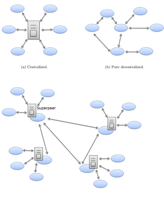
Although P2P systems are supposed to operate in a fully decentralized man-ner, in practice, we observe that various degrees of decentralization can be applied to the routing protocols of unstructured overlays. Accordingly, we clas-sify unstructured overlays into three groups: centralized, pure decentralized and partially decentralized with superpeers.
Centralized In these overlays, a central server is in charge of indexing all the peers and their shared content as shown in Figure 5a. Whenever a peer requests some content, it directly sends its query to the central server which identifies the peer storing the requested object. Then, the file is transferred between the two peers. The now-defunct Napster9 [8] adopted such a centralized architecture.
9
(a) Centralized. (b) Pure decentralized.
(c) Partially decentralized with superpeers.
Figure 5: Types of unstructured P2P overlays.
Pure Decentralized In pure decentralized overlays, all peers have equal roles as shown in Figure 5b. Each peer can issue queries, serve and forward queries of other peers. Query routing is typically done by blindly flooding the query to neighbors. The flooding mechanism has been further refined, in a way that nowadays we find several variants of flooding like random walks and iterative deepening. These techniques are explained in more detail in Section 3.2.2. Of the many existing unstructured P2P systems, Gnutella [30, 42, 41] is one of the original pure decentralized networks.
Partially Decentralized with Superpeers In these overlays, high-capacity peers are assigned the role of superpeers, and each superpeer is reponsible of a set of peers, indexing their content and handling queries on their behalf. Superpeers are then organized in a pure decentralized P2P network and can communicate to search for queries (see Figure 5c). They can be dynamically elected and replaced in the presence of failures. Gnutella2 [82] is another version of Gnutella that uses superpeers; Edutella [59] and FastTrack/Kazaa [51] are also popular examples of hybrid networks.
The higher is the degree of decentralization, the more the network is fault-tolerant and robust against failures, because there will be no single point of failure due to the symmetry of roles. However, the higher is the degree of cen-tralization, the more efficient is the search for content. Thus, the hybrid overlay strikes a balance between the efficiency of centralized search, and the load bal-ancing and robustness provided by means of decentralization. Furthermore, it can take advantage of the heterogeneity of capacities (e.g., bandwidth, process-ing power) across peers. That is why recent generations of unstructured overlays are evolving towards hybrid overlays.
3.2.2 Decentralized Routing Techniques
In decentralized routing, blind techniques are commonly used to search for con-tent in unstructured networks. Blind techniques route the query without any information related to the location of the requested object. A peer only keeps references to its own content, without maintaining any information about the content stored at other peers. Blind techniques can be grouped into three main categories: breadth-first-search, iterative deepening and random walk.
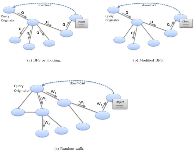
Breadth-First-Search (BFS). Originally, unstructured systems relied on the flooding mechanism which is more formally called Breadth-First-Search (BFS). Illustrated in Figure6a, the query originator sends its query Q to its neighbors, which in turn forward the message to all their neighbors except the sender and so on. The query is associated with a Time-To-Live (TTL) value, which is de-creased by one when it travels across one hop in the P2P overlay. At a given peer, the message comes to its end if it becomes redundant (i.e., no further neighbors) or the TTL value becomes zero. Query responses follow the reverse path of the query, back to the requester peer. The main merits of this ap-proach are its simplicity, reliability, and its high network coverage, i.e., a large number of peers could be reached within a small number of hops. However, measurements in [74] have shown that although 95% of any two peers are less than 7 hops away, flooding generates 330 TB/month in a Gnutella network with only 50,000 nodes. This heavy traffic compromises the benefits of unstructured systems and drastically limits their scalability. The reasons behind the traffic burden of flooding are blindness and redundancy. First, a peer blindly forwards the query without any knowledge about how the other peers can contribute to the query. Second, a peer may receive the same query message multiple times because of the random nature of connections in an unstructured overlay. This can result in huge amounts of redundant and unnecessary messages.
In [43], modified BFS has been proposed in attempt to reduce the traffic overhead of flooding. Upon receiving a query, a peer randomly chooses a ratio
of its neighbors to send or forward the query (see Figure6b). However, this approach may loose many of the good answers which could be found by BFS.
(a) BFS or flooding. (b) Modified BFS.
(c) Random walk.
Figure 6: Blind routing techniques of unstructured overlays.
Iterative Deepening. This approach [98, 54] is also called expanding ring. The query originator performs consecutive BFS searches with successively larger TTL. A new BFS follows the previous one by expanding the TTL, if the query has not been satisfied after a predefined time period. The algorithm ends when the required number of answers is found or the predefined maximum TTL is reached. In case the results are not in the close neighborhood of the query originator, this approach does not address the duplication issue and adds con-siderable delay to the response time.
Random Walk. In the standard algorithm, the query originator randomly selects one of its neighbors and forwards the query to that neighbor. The latter, in turn, forwards the query to one randomly chosen neighbor, and so on until
the query is satisfied. Compared to the basic BFS, this algorithm reduces the network traffic, but massively increases the search latency.
In the k-walker random walk algorithm [54], the query originator forwards k query messages to k randomly chosen neighbors (k is a value specified by the application). Each of these messages follows its own path, having intermediate peers forward it to one randomly chosen neighbor at each step. These query messages are also known as walkers and are shown in (Figure6c) as W 1 and W 2. When the TTL of a walker reaches zero, it is discarded. Each walker periodically contacts the query originator, asking whether the query was satisfied or not. If the response is positive, the walker terminates. This algorithm achieves a significant message reduction since it generates, in the worst case, k ∗ T T L routing messages, independently of the underlying network. Nevertheless, a major concern about this algorithm is its highly variable performance because success rates are highly variable and dependable on the network topology and the random choices made. In addition, the random walk technique does not learn anything from its previous successes or failures.
3.2.3 Behavior under Churn and Failures
It is well known that P2P networks are characterized by a high degree of churn [31]. Therefore, it is vital to examine the behavior of P2P networks in highly dynamic environments where peers join and leave frequently and concurrently.
The maintenance of unstructured overlays merely rely on the messages ping, pong and bye: pings are used to discover hosts on the network, pongs are replies to pings and contain in formation about the responding peer and other peers it knows about, and byes are optional messages that inform of the upcoming closing of a connection.
After joining the overlay network (by connecting to boostrap peers found in public databases), a peer sends out a ping message to any peer it is connected to. The peers send back a pong message identifying themselves, and also propagate the ping message to their neighbors. When a peer gets in contact with a new peer, it can add it as a neighbor in its routing table in a straigthforward manner. A peer that detects the failure or leave of a neighbor simply removes it from its routing table. If a peer becomes disconnected by the loss of all of its neighbors, it can merely repeat the bootstrap procedure to re-join the network [10].
The measurements in [67] show that the bandwidth consumption due to maintenance messages is reasonably low in the unstructured Gnutella system. Peers joining and leaving the Gnutella network have little impact on other peers or on the placement of shared objects, and thus do not result in significant maintenance traffic.
To resume, there are few constraints on the overlay construction and content placement in unstructured networks: peers set up overlay connections to an arbitrary set of other peers they know, and shared objects can be placed at any peer in the system. The resulting random overlay topology and content distribution provides high robustness to churn [67]. Furthermore, the routing mechanism greatly rely on flooding which yields randomness and repetitiveness and thus more robustness. Given that a query takes several parallel routes, the disruption of some routes due to peer failures does not prevent the query from being propagated throughout the P2P network.
3.2.4 Strengths and Weaknesses
Unstructured P2P systems exhibit many simple yet attractive features, such as high flexibility and robustness under churn and failures. For instance, the freedom in content placement provides maximum flexibility in selecting policies for replication and caching.
Unstructured overlays are particularly used to support file-sharing applica-tions for two main reasons. First, since they introduce no restriapplica-tions on the man-ner to express a query, they are perfectly capable of handling keyword search, i.e., searching for files using keywords instead of the exact filenames. Second, file popularity derives a kind of natural file replication among peers, which induces high availability. Indeed, peers replicate the copies of files they request when they download them.
However, the main Achilles heel of unstructured systems are their blind rout-ing mechanisms which incur severe load on the network and give no guarantees on lookup efficiency. Because of the topology randomness, a query search ne-cessitates O(n) hops (where n is the total number of peers), generates many redundant messages and is not guaranteed to find the requested object. Many studies such as [74] and [75] claim that the high volume of search traffic threat-ens the continued growth of unstructured systems. Indeed, the measurements in [74] have shown that although 95% of any two peers are less than 7 hops away, flooding generates 330 TB/month in a Gnutella network with only 50,000 nodes.
3.3
Structured Overlays
The evolution of research towards structured overlays has been motivated by the poor scaling properties of unstructured overlays. Structured networks discard randomness and impose specific constraints on the overlay topology [67]. They remedy to the blind search by tightly controlling the content placement. As a result, they provide an efficient, deterministic search: they can locate any object within a bounded number of hops.
More precisely, a structured overlay provides a distributed index scheme, by mapping content to locations (e.g., an object identifier is mapped to a peer address). To achieve this, objects and peers are assigned unique identifiers (re-spectively keys and IDs) from the same identifier space (e.g., hashing filename or url for an object and the IP address for a peer). Then, this identifier space is dynamically partitionned among peers, so that each peer is responsible for a specific key space partition. Accordingly, a peer stores the objects or point-ers related to objects with respect to its key partition. The topology dictates for each peer a certain number of neighbors. The peer holds a routing table that associates its neighbors’s identifiers to their IP addresses. Then a routing algorithm is defined to allow a deterministic key-based search. The main repre-sentative of structured overlays is the Distributed Hash Table (DHT ) which is presented and dicussed in the following.
3.3.1 DHT Routing
At a fundamental level, DHTs can be viewed as content addressing and lookup engines. A DHT provides content and peer addressing via consistent hashing
[45]. This technique enables a uniform hashing of values and thereby evenly places or maps content to peers. The addressing mechanism serves as a dis-tributed and semantic-free index, because it gives information about the location of content based on hash-based keys.
The lookup engine of the DHT mainly consists in locating the target peer by means of routing over the overlay. The routing protocol tightly depends on the different implementations of DHT and more precisely the routing geometries [32]. Nonetheless, all routing protocols aim at providing efficient lookups as well as minimizing the routing state10that should be maintained at each peer.
Most of them exhibit almost similar space and time complexity. That is, the routing table of peer contains at most O(log N ) entries and a lookup is normally performed in O(log N ) hops where N is the total number of nodes in the DHT [34].
The routing geometry mainly defines the manner in which neighbors and routes are established. According to [32], there are 6 basic types of routing geometries: tree, hypercube, ring, butterfly, XOR and hybrid. The main factor that distinguishes these geometries is the degree of flexibility they provide in the selection of neighbors and routes.
Neighbor selection refers to how the routing table entries of a peer are es-tablished, whereas route selection refers to how the next-hop can be determined in a routing process. Flexibility in the selection of neighbors and routes has a significant impact on the robustness and locality-awareness properties of the DHT-based system [32]. When allowing some freedom in the selection of neigh-bors and routes, one can choose neighneigh-bors and next routes, respectively, based on proximity. For instance, if the choice of neighbors is completely deterministic, it prevents the addition of features on top of the initial DHT proposal in order to achieve locality-aware routing tables. Further, flexible selections interfere in failures because they describe how many alternatives are there for the neighbor or the next-hop in case they are down. For instance, if there are no option for a next-hop, or only a few, this may destabilize or interrupt the routing process, which can greatly increase the number of hops or/and the latency.
In the following, we look at 4 geometries, tree, hypercube, ring and hybrid and discuss their flexibility degrees.
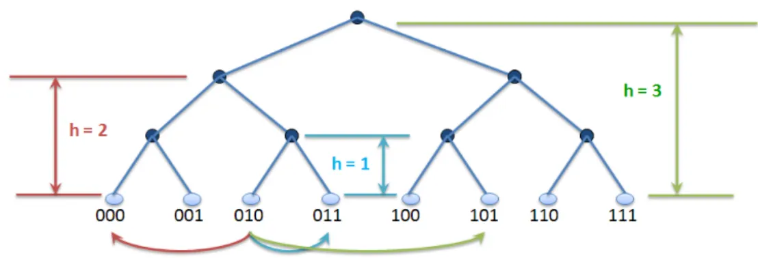
Tree. Peer IDs are the leaves of a binary tree of height log N , where N is the number of nodes in the tree (see Figure7). The responsible for a given key is the peer whose identifier has the highest number of prefix bits which are common with the key. The distance between any two peers is the height of their smallest common subtree. Each peer has log N neighbors, such that the hth neighbor is at distance h from the peer. Let us consider the tree of height equal to 3 in Figure7. The peer with ID = 010 has the peer with ID = 011 as its 1st neighbor because their smallest common subtree is of height h = 1. Their IDs share a prefix of two bits and differ on the last bit. Similarly, the peer with ID = 010 has chosen the peer with ID = 000 as its 2nd because their smallest common subtree is of height h = 2. Their IDs share a prefix of one bit and differ on the two others. Routing is performed such that the prefix match between the target key and the ID of the intermediate peer is increased by one at each
Figure 7: Tree routing geometry.
hop, until reaching the responsible peer. The well-known DHT implementation Tapestry [99] falls into this category.
The tree geometry gives a great deal of freedom to peers in choosing their neighbors; when choosing the ith neighbor, a peer has 2i−1options. In the tree
example, the peer with ID = 010 has 22−1 = 2 choices for its 2nd neighbor:
the peer with ID = 000 and the peer with ID = 001 because they both belong to the subtree of height h = 2. However, this approach has no flexibility in the selection of routes: there is only one neighbor which the message must be forwarded to, i.e., this is the neighbor that has the most common prefix bits with the given key.
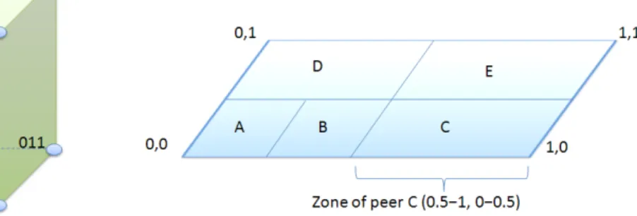
Hypercube. This geometry is based on a d-dimensional Cartesian coordinate space that is partitioned into a set of separate zones such that each peer is attributed one zone. Peers have unique identifiers with log N bits, where N is the total number of peers of the hypercube. Each peer p has log N neighbors such that the identifier of the ith neighbor and p differ only in the ith bit (see Figure8a). Query routing proceeds by greedily forwarding the given key via intermediate peers to the peer that has minimum bit difference with the key. Thus, it is somehow similar to routing on the tree. The difference is that the hypercube allows bit differences to be reduced in any order while with the tree, bit differences have to be reduced in strictly left-to-right order. CAN [69] uses a routing geometry similar to hypercubes. Figure8b shows a 2-dimensional [0; 1] ∗ [0; 1] coordinate space partitioned between 5 peers.
There are (log N )! possible routes between two peers, which provides high route flexibility. However, each peer in the coordinate space does not have any choice over its neighbours coordinates since adjacent coordinate zones in the coordinate space cannot change. Therefore, the high route selection flexibility provided by Hypercubes is at the price of poor neighbor selection flexibility. Ring. Peers are arranged in a one-dimensional cyclic identifier space and or-dered clockwise with respect to their identifiers. Chord [89] represents the pro-totypical DHT ring. In Chord, each peer has an m-bit identifier, and the re-sponsible for a key is the first peer whose identifier is equal to or greater that the
(a) Hypercube routing geometry. (b) Hypercube-like structure of CAN.
Figure 8: Hypercube routing geometry.
key. Each peer p has log N neighbors such that the ith neighbor has a distance from the peer clockwise in the circle equal to 2i−1mod N . Hence, any peer can route a given key to its responsible in log N hops because each hop cuts the distance to the destination by half. In Figure9, the Chord peer with ID = 8 maintains 8 entries in its routing table called finger table.
Although Chord specifies the set of neighbors for each peer, the ring ge-ometry does not necessarily needs such rigidity in neighbor selection. In fact, the log N lookup bound is preserved as long as the ith neighbor is chosen from the range [2i−1mod N, 2imod N ]. This provides a great deal of neighbour
se-lection flexibility because each peer would have 2i−1options in selecting its ith
neighbor. Moreover, to reach a destination, there are approximately (log N )! possible routes. Therefore, the ring geometry also provides good route selection flexibility.
Hybrid. This geometry employs a combination of geometries. As a represen-tative example, Pastry [76] is a popular DHT implementation that combines the tree and ring geometries, aiming at a locality-aware routing. To achieve this, each peer maintains a routing table, a leaf set, and a neighbourhood set. The routing table resembles the tree structure described previously, while the leaf set acts as the ring in routing. The neighbourhood set is used to maintain locality properties. During a lookup process, a peer uses first the tree structure represented by its routing table, and only falls-back to the ring via its leaf set if routing in the tree fails. This is why Pastry provides flexibility in neighbor selection, similar to the tree geometry. However, the matter is more sublte with respect to route selection flexibility. Given that a peer maintains an ordered leafset, it is able to take hops between peers with the same prefix (i.e., between branches of the tree) and still retain the bits that were fixed previously; this however does not necessarily preserve the log N bound on the number of hops. 3.3.2 Behavior under Churn and Failures
Preserving the topology constraints is crucial to guarantee the correctness of lookup in structured overlays. However, churn and failures highly affect DHTs.
Figure 9: Ring routing geometry. Example of Chord with 10 peers and a peer ID of m = 6 bits.
When peer failures or leaves occur, they deplete the routing tables of the existing peers. Recovery algorithms are used to repopulate the routing tables with live peers, so that routing can continue unabated. The recovery can be reactive (upon detecting the failure of a peer referenced by the routing table) like in Pastry [76] or periodic (upon regular time intervals in the background) like in Chord [89]. Basically, the peer exchanges entries from the routing table with peers from its routing table and accordingly update its routing table. After a single peer leaves the network, most DHTs require O(log N ) repair operations, i.e., updates of routing tables affected by the leave (N is the total number of peers) . When a peer unexpectedly fails, the DHT needs more time and effort to first detect the failure and then repair the affected routing tables. It should also notify the application to take specific measures so that the content held by failed peers is not lost. Several approaches have been proposed to prevent this problem, most notably the replication of content at peers with IDs numerically close to the content’s key [77].
When a new peer joins the overlay network, the DHT should detect the arrival and inform the application of the set of keys that the new peer is re-sponsible for so that the relevant content is moved to its new home. Similarly to leaves and failures, the recovery algorithms should update the routing tables of the peers concerned by the new arrival.
However, if the churn rate is too high, the overhead caused by these repair operations can become dramatically high and could easily overwhelm peers [10]. Furthermore, recovery protocols take some time to repair and update the routing tables affected by joins and/or leaves. Given that new arrivals and de-partures are frequent in P2P environments, one must check the static resilience of a DHT [32], i.e., how well the DHT routing algorithm can perform before the overlay has recovered (before routing tables are restored and keys migrated
to new homes). DHTs with low static resilience require much faster recovery algorithms to be similarly robust. In such DHTs, requests that fail in routing should retry the lookup after a pause. A DHT with routing flexibility provides high static resilience because it has many alternate paths available to complete a lookup (see Section 3.3.1).
The analysis in [73] has examined the effects of churn on existing DHT implementations and derived two main observations. A DHT may either fail to complete a lookup, or return inconsistent answers (e.g., return the address of a peer that is no more responsible for the requested key). On the other hand, a DHT may continue to return consistent answers as churn rates increase, but it can suffer from a substantial increase in lookup latency.
3.3.3 Strengths and Weaknesses
Structured overlays offer strong guarantees on lookup efficiency while limiting the routing overhead. In particular, the ring topology is the best compromise that supports many of the properties we desire from such overlays. They have been used in a variety of applications such as content storage (e.g., OceanStore [49], Pastry [77]), multicast services (e.g., Bayeux [100], Scribe [78]) or large-scale query processing engines (e.g., Pier [35]).
However, two criticisms arise against these overlays and constitue major hurdle in the adoption of such systems. First, the tightly controlled topology requires high maintenance in order to cope with the frequent joins and leaves of peers. Moreover, studies [73] have shown that structured systems exhibit less than desirable performance under high churn rates because routing tables are affected and take time to be repaired. A second criticism concerns the limited flexibility provided by structured systems wrt. the autonomy of peers and the lookup functionality. Peers cannot freely choose their neighbors nor their responsabilities. Further, structured systems are designed in a way to provide key-based lookup which is convenient to exact-match queries. Their ability to support keyword searches and more complex queries is still an open issue.
Thus, structured overlays are the perfect match for applications that seek a scalable and guaranteed lookup but do not witness highly dynamic populations.
3.4
Requirements of P2P Systems
Based on this preliminary study on P2P systems, we observe that they introduce new requirements in respect of content sharing. The study in [18] identifies the following requirements:
Autonomy defines the level of freedom granted to peers, mainly with respect to the placement of content. This is required to give peers proper incentives to cooperate. Indeed, it is usually not desired and rarely enabled to force storing content on peers.
Expressiveness refers to the flexibility in query formulation. It should allow the user to describe the desired content at the level of detail that is appropriate to the target application.
Quality of service has the most influence on user satisfaction. It can be defined with metrics like response time and hit ratio.
Efficiency refers to the efficient use of resources of the P2P network (bandwidth, processing power, storage). Given the high rate of failures and churn, the maintenance protocol should neither compromise the gains with its overhead nor degrade the system performance. Also, efficiency implies that the routing protocol does not overload the network or the peers while not missing the available content.
Robustness means that efficiency and quality of service are provided despite the occurrence of peer failures.
Security is a major challenge given the open nature of P2P networks. With respect to content distribution, one of the most critical issues is the content authenticity which deals with the problem of distinguishing fake documents from original ones. We do not focus on this requirement in our study.
REQUIREMENTS UNSTRUCTURED STRUCTURED
Autonomy free to choose neighbors and content tight control on neighbors and content
Expressiveness keywords exact-match
Quality of service no guarantees deterministic
Efficiency efficient maintenance efficient lookup
Robustness suitable for high churn problems under high churn
Table 1: Comparison of P2P overlays.
Table 1 summarizes how the requirements are achieved by the two main classes of P2P networks. This is a rough comparison to understand the respec-tive merits of each class. Obviously, there is room for improvement in each class of P2P networks. Regarding efficiency, structured systems provide a highly ef-ficient lookup at the cost of a significant maintenance overhead, in opposition to unstructured systems.
Beyond this classical classification of P2P systems, there exist new trends in the P2P literature, that focus on other considerations and incur new challenges on the design of a P2P system. This is further investigated in Section 4.
4
Recent Trends for P2P Content Distribution
We have, so far, discussed P2P systems from a classical perspective. However, today’s research is evolving towards more sophisticated issues about P2P sys-tems, from the perspective of content distribution.
Recently, some have started to justify that unstructured and structured over-lays are complementary, not competing. It is actually easy to demonstrate that depending on the application, one or the other type of overlay is clearly more adapted. In order to make use of the desirable features provided by each topol-ogy, there are efforts underway for combining both in the same P2P systems.
Further, the overlay can be refined through extracting and leveraging in-herent structural patterns from P2P networks. These patterns can stem from the underlying physical network (e.g., physical proximity between peers) or be defined at the application layer (e.g., interest-based proximity between peers).
Matching the overlay with the underlying physical network greatly contributes in reducing communication and data transfer costs as well as user-perceived latencies. Additionally, leveraging interests of peers to organize them can ease the search for content and guide the routing of queries.
Another recent trend is the usage of gossip protocols as a mean to build and maintain the P2P overlay. Gossiping is also used to feed the overlay with indexing information in order to facilitate content search.
In the following, we present in more detail the aforementioned trends. In Section 4.0.1, we detail locality-based overlay matching and the existing so-lutions along these lines. Then, we present interest-based overlay matching in Section 4.0.2. In Section 4.0.3, we introduce the usage of gossip protocols in P2P systems. Finally, we review the existing approaches that combine several over-lays in Section 4.0.4. Finally, we identify the major challenges to be met when aiming to achieve these new trends and accordingly discuss the aforementioned approaches.
4.0.1 Trend 1: Locality-Based Overlay Matching
As introduced in Section 3, the overlay topology defines application-level connec-tions between peers and completely abstracts all features about the underlying physical network (e.g., IP level). In other terms, the neighborhood of a node is set without much knowledge of the underlying physical topology, causing a mismatch between the P2P overlay and the physical network. Figure4 clearly illustrates the mismatch between a P2P overlay and the underlying Internet. As an example, peer A has peer B as its overlay neighbor while peer C is its physical neighbor. This can lead to inefficient routing in the overlay because any application-level path from peer A towards the nearby peer C traverses distant peers.
More precisely, the scalability of a P2P system is ultimately determined by its efficient use of underlying resources. The topology mismatch problem imposes substancial load on the underlying network infrastructure, which can eventually limit the scalability [74]. Furthermore, it can severely deteriorate the performance of search and routing techniques, typically by incurring long latencies and excessive traffic. Indeed, many studies like [80] have revealed that the P2P traffic contributes the largest portion of the Internet traffic and acts as a leading consumer of Internet bandwidth. Thus, a fundamental challenge is to incorporate IP-level topological information in the construction of the overlay in order to improve routing performance. This topological information could also be used in the selection of close-by search results to ensure a good user experience. Topological information refers to locality-awareness because it aims at finding peers close in locality. Below, we present the main representative approaches that propose locality-based matching schemes.
Physical Clustering. In [48], clustering has been used to group physically close peers into clusters. The approach relies on a centralized engine to identify clusters of close peers under common administrative control. To achieve this, the central server uses IP-level routing information which is not directly avail-able to end-user applications. Thus, the main drawbacks of this approach are the centralized topology control and the topological information itself, which prevents it from being scalable and robust to churn.
In the context of application-level multicast and media streaming, many solutions aim at constructing a locality-aware overlay because of the strong requirements on the delivery quality. The NICE protocol [2] builds a hierarchy of clusters rooted at the source, whith close peers belonging to the same part of the hierarchy. However, maintaining the hierarchy under churn may incur high overhead and affect performance.
LTM Technique. The LTM (Location-aware Topology Matching ) technique [53] targets unstructured overlays. It dynamically adapts connections between peers in a completely decentralized way. Each peer issues a detector in a small region so that the peers receiving the detector can record the relative delay. Ac-cordingly, a receiving peer can detect and cut most of the inefficient logical links and add closer peers as neighbors. However, this scheme operates on long-time scales where the overlay is slowly improved over time.Given that participants join and leave on short time-scales, a solution that operates on long-time scales would be continulally reacting to fluctuating peer membership without stabiliz-ing.
Locality-Aware Structured Overlays. While the original versions of struc-tured overlays did not take locality-awareness into account, almost all of the re-cent versions make some attempt to deal with this primary issue. [71] identifies three main approaches.
Geographic layout: the peer IDs are assigned in a manner that ensures that peers that are close in the physical network are close in the peer ID space.
Proximity routing: the routing tables are built without locality-awareness but the routing algorithm aims at selecting, at each hop, the nearest peer among the ones in the routing table. For this, flexibility in routing selec-tion is required as layed out in Secselec-tion 3.3.1.
Proximity neighbor selection: the construction of routing tables takes locality-awareness into account. When several candidate peers are avail-able for a routing tavail-able entry, a peer prefers the one that is close in locality. To achieve this, flexibility in neighbor selection is required as pointed out in Section 3.3.1.
Pastry [76] and Tapestry [99] adopt proximity neighbor selection. In or-der to preferentially select peers and fill routing tables, these systems assume the existence of a function (e.g., round-trip-time RTT) that allows each peer to determine the physical distance between itself and any another peer. Al-though this solution leads to much shorter query routes, it requires expensive maintenance mechanisms under churn. As peers arrive and leave, routing tables should be repaired and updated. Without timely repairing, the overlay topology will diverge from optimal condition as inefficient routes gradually accumulate in routing tables.
A design improvement [70] of CAN aims at achieving geographic layout. It relies on a set of well-known landmarks spread across the network. A peer mea-sures its round-trip time (RTT) to the set of landmarks and orders them by increasing latency (i.e., network distance). The logical space of CAN is then
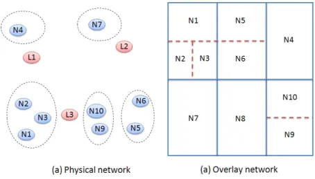
divided into bins such that each possible landmarks ordering is represented by a bin. Physically close nodes are likely to have the same ordering and hence will belong to the same bin. This is illustrated in Figure 10. We have 3 landmarks (i.e., L1, L2, and L3) and, accordingly, the CAN coordinate space is divided into 6 bins (3! = 6). Since peers N1, N2, and N3 are physically close (see Figure 10 (a)), such peers produce the same landmark ordering, i.e., L3¡L1¡ L2. As a result, N1, N2, and N3 are placed in the same bin of the overlay network, and they take distinct neighbor zones (see Figure 10 (b)). The same approach applies to other peers. Notice that such approach is not perfect. For instance, peer N10 is closer to N3 than N5 in the physical network whereas the oppo-site situation is observed in the overlay network. Despite its limited accuracy, this technique achieves fast results and copes well with dynamicity. In addi-tion, binning has the advantage of being simple to implement and scalable since peers independently discover their bins without communicating with other par-ticipants. Furthermore, it does not incur high load on the landmark machines: they need only echo ping messages and do not actively initiate measurements nor manage measurement information. To achieve more scalability, multiple close-by nodes can act as a single logical landmark.
Figure 10: Locality-aware construction of CAN
An observation about the aforementioned locality-aware schemes is that the technique used in Pastry and Tapestry is very protocol-dependent and thereby cannot be extended to other contexts in a straigthforward manner, whereas the binning technique can be more generally applied in contexts other than in structured overlay, like unstructured overlays.
4.0.2 Trend 2: Interest-Based Topology Matching
In attempt to improve the performance of P2P systems and the efficiency of search mechanisms, some works have addressed the arbitrary neighborhood of peers from a semantic perspective. Recent measurement studies [33, 28, 85] of
P2P workloads have demonstrated the inherent presence of semantic proximity between peers, i.e., similar interests between peers. They have shown that exploiting the implicit interest-based relationships between peers may lead to improvements in the search process. In short, they have reached the following conclusion: “if a peer has an object that I am interested in, it is very likely that he will have other objects that I am (or will be) interested in”.
These interest-based relationships can be translated into logical connections between peers that can either replace or be added on top of a peer neighborhood. If we consider Figure 4, peer A has peer B as a neighbor specified by its overlay topology and could have extra connections with semantically similar peers like peer D. Then, these semantic connections can be used to achieve efficient search. In the following, we discuss two representative works along these lines. They were initially proposed for unstructured overlays. When applying one of them, a peer maintains two types of neighbors: its neighbors in the unsructured overlay (e.g., random peers) and its interest-based neighbors. Upon receiving a query, the peer uses its interest-based neighbors first; if this first phase fails the normal search phase is performed via its normal neighbors. In superpeer overlays, the first phase can be used to bypass the superpeers thus alleviating their load. Semantic Clustering. Garcia-Molina et al. [16] introduces the concept of se-mantic overlays and advocates their potential performance improvement. Peers with semantically similar content are grouped into clusters together. Clusters can overlap because a peer can simultaneously belong to several clusters related to its content. To achieve this, the authors assume global knowledge of the se-mantic grouping of the shared documents and accordingly choose a predefined classification hierarchy. Then, each peer decides which clusters to join by clas-sifying its documents against this hierarchy. To join its clusters, the peer finds peers belonging to these clusters by flooding the network. However, It is not clear how this solution performs in the presence of dynamic user preferences. Interest-Based Shortcuts. In [85], the concept of shortcut is proposed, al-lowing peers to add direct connections to peers of similar interests besides their neighbors. The similarity of interests are captured implicitly based on recent downloads and accordingly, interest-based shortcuts are dynamically created in the network: basically, a peer adds shortcuts to peers among those from which it had recently downloaded content. In practice, these shortcuts are discovered progressively while searching for content via flooding. Furthermore, the time for building interest-based groups is non-trivial, and these groups may be no more useful when the peer goes offline and then online again, due to the dynamic nature of P2P networks.
The aforementioned schemes may also be applied to structured overlays. In addition to its routing table, a peer may maintain interest-based neighbors and use them conjunctly. However, this increases the routing state at each peer and incurs extra storage and update overhead.
4.0.3 Trend 3: Gossip Protocols as Tools
We now present the usage of gossip protocols in P2P systems. They can serve as efficient tools to achieve new P2P trends in a scalable and robust manner.
Gossip has recently received considerable attention from researchers in the field of P2P systems [47]. In addition to their inherent scalability, they are simple to implement, robust and resilient to failures. They are designed to deal with continuous changes in the system, while they exhibit reliability despite peer failures and message loss. This makes them ideally suited for large-scale and dynamic environments like P2P systems. In this section, we provide generic definition and description of gossip protocols, then we investigate how P2P systems can leverage these protocols.
Generic Definition Gossip algorithms mimic rumor mongering in real life. Just as people pass on a rumor by gossiping to their contacts, each peer in a distributed system relays new information it has received to selected peers which in their turn, forward the information to other peers, and so on. They are also known as epidemic protocols in reference to virus spreading [19].
Generic Algorithm Description The generic gossip behavior of each peer can be modeled by means of two separate threads: an active thread which takes the initiative to communication, and a passive thread which reacts to incom-ing initiatives [47]. Peers communicate to exchange information that depends strictly on the application. The information exchange can be performed via two strategies : push and pull. A push occurs in the active thread, i.e., the peer that initiates gossiping shares its information upon contacting the remote peer. A pull occurs in the passive thread, i.e., the peer shares its information upon being contacted by the initiating peer. A gossip protocol can either adopt one of these strategies or the combination of both (i.e., push-pull which implies a mutual exchange of information during each gossip communication).
Figure 11 illustrates in more detail a generic gossip exchange. Each peer A knows a group of other peers or contacts and stores pointers to them in its view. Also, A locally maintains information denoted as its state. Periodically, A selects a contact B from its view to initiate a gossip communication. In a pull-push scheme, A selects some of its information and sends them to B which, in its turn, does the same. Upon receiving the remote information, each one of A and B merges it with its local information and update their state. At that point, how a peer deals with the received information and accordingly update its local state is highly application dependent.
How P2P Systems Leverage Gossip Protocols Gossip stands as a tool to achieve 4 main purposes [47]: dissemination, resource monitoring, topology construction and peer sampling. Figure 12 illustrates these gossip-based services and how they interfere in a P2P system that is represented by an overlay layer and a search layer.
Introduced by Demers et al. [19], dissemination has traditionally been the purpose of gossiping. In short, the aim [26] is to spread some new information throughout the newtork by letting peers forward messages to each other. The information gets propagated exponentially through the network. In general, it takes O(logN ) rounds to reach all peers, where N is the number of peers. Figure 12 shows that gossip-based dissemination can be used to feed the search layer with indexing information useful to route queries. Basically, a peer can
(a) Select contact. (b) Exchange state information.
(c) Merge and update local state.
Figure 11: Peer A gossiping to Peer B.
maintain and gossip information about the content stored by other peers and decide accordingly to which peers it should send a query.
Then, gossiping has turned out to be a vehicule of resource monitoring in highly dynamic environments. It can be used to detect peer failures [72], where each peer is in charge of monitoring its contacts, thus ensuring a fair balance of the monitoring cost. Further, gossip-based monitoring can guarantee that no node is left unattended, resulting in a robust self-monitoring system. In Figure 12, the monitoring service is used to maintain the overlay under churn by monitoring a peer’s neighbors. In addition, it interferes in the search layer to monitor indexing information in face of content updates and peer failures.
Recently, various researches have explored gossiping as a mean for over-lay construction and maintenance according to certain desirable topolo-gies (e.g., interest-based, locality-based, random graphs), without requiring any global information or centralized administration. In such systems, peers self-organize under the target topology, via a selection function that determines which neighbors are optimal for each peer (e.g., semantic or physical


![Figure 3: Typical user interaction with a website using Akamai services [91].](https://thumb-eu.123doks.com/thumbv2/123doknet/7798474.260749/10.892.203.689.341.578/figure-typical-user-interaction-website-using-akamai-services.webp)