To link to this article: DOI:10.1007/s12008-015-0272-5
URL:
http://dx.doi.org/10.1007/s12008-015-0272-5
This is an author-deposited version published in:
http://oatao.univ-toulouse.fr/
Eprints ID: 13716
To cite this version:
Cailhol, Simon and Fillatreau, Philippe and Zhao, Yingshen and Fourquet,
Jean-Yves A hierarchic approach for path planning in Virtual Reality.
(2015) International Journal on Interactive Design and Manufacturing
(IJIDeM), vol. 9. ISSN 1955-2513
O
pen
A
rchive
T
oulouse
A
rchive
O
uverte (
OATAO
)
OATAO is an open access repository that collects the work of Toulouse researchers
and makes it freely available over the web where possible.
Any correspondence concerning this service should be sent to the repository
A hierarchic approach for path planning in Virtual Reality
Simon Cailhol
Philippe Fillatreau
Yingshen Zhao
Jean-Yves Fourquet
March 20, 2015
Abstract
This work considers path-planning processes for manipu-lation tasks such as assembly, maintenance or disassem-bly in a virtual reality (VR) context. The approach con-sists in providing a collaborative system associating a user immersed in VR and an automatic path planning process. It is based on semantic, topological and geometric repre-sentations of the environment and the planning process is split in two phases: coarse and fine planning. The au-tomatic planner suggests a path to the user and guides him trough a haptic device. The user can escape from the proposed solution if he wants to explore a possible better way. In this case, the interactive system detects the users intention and computes in real-time a new path starting from the users guess. Experiments illustrate the different aspects of the approach: multi-representation of the en-vironment, path planning process, users intent prediction and control sharing.
1 Introduction
The industrial product development process is going faster and faster with more and more complex products. This leads to a need of tools allowing to rapidly test a product at all the PLM stages during the design phase. Performing such tests with virtual prototypes accelerates the design process while reducing its cost. There is a particular need for performing the tasks that involve hu-man operator hu-manipulation with virtual prototypes. Here comes the interest of Virtual Reality (VR) to run these tests [11].
Among these tasks, VR community has studied assem-bly/disassembly, dismantling and maintenance. To per-form such tasks in VR simulation, the means for
inter-action allowing manipulating the CAD models is one of the main issues [12, 5, 18]. Another issue is to identify the system mechanical constraints to provide the VR operator with an assembly/disassembly plan [14, 15].
The main issue of such tasks is to find paths for the sys-tems CAD models. For this issue of such applications, we propose a collaborative path-finding system based on the interaction of a user immersed in a VR simulation and an automatic path planning process inspired from robotics.
Collaboration is defined as follows. The system pro-vides a initial planned path and the user is guided along a computed trajectory through an haptic device. However, the user can disagree the proposed path and try to go in another direction. The system must compute a new path every time the user tries to test another solution. Thus, it must be able to take into account the users interactions in real time to update the suggested path and it requires control sharing between the user and the planner while performing the task.
Robotics path planners mainly deal with geometric as-pects of the environment. The VR context of our plan-ner involves a human in the loop with a different environ-ment representation. Thus, we chose to split the planning process in two phases: a coarse planning dealing with topological and semantic models of the environment (the places, their semantics and their connectivity) and a fine planning dealing with geometry and semantics (geometry of obstacles and places and their complexity). This plan-ning process partitioplan-ning provides a framework compati-ble with the human path planning process described in [3]. Thus, the proposed interactive path planner is based on a multi-layer environment representation (semantic, topo-logical and geometric). All these environment models are used by distinct planner layers to perform the coarse (se-mantic and topological aspects) and fine (se(se-mantic and 1
Table 1: Main path planning methods
Global approaches Local approaches
Deterministic strategies
Cells decomposi-tion,
Roadmap Potential field
Probabilistic
strategies ProbabilisticRoadMap
Rapidly-exploring Random Tree, Rapidly-exploring Dense Tree geometric aspects) planning and to assist VR user.
2 State of the art
2.1 Automatic path planning
The automatic path planning issue has been deeply stud-ied in robotics. These works are strongly based on the Configuration Space (CS) model proposed by [20]. This model aims at describing the environment from a robots Degrees of Freedom (DoF) point of view. The robot is described using a vector where each dimension represents one of his DoF. A value of this vector is called a config-uration. So, all the possible values of this vector form the CS. This CS can be split into free space and colliding space (where the robot collides with obstacles of the envi-ronment). With this model, the path planning from a start point to a goal point consists in finding a trajectory in the free space between these two points in the CS.
The main methods for path planning are given in the Table 1 where we distinguished the deterministic from the probabilistic ones, but also, the ones involving global ap-proach from the ones involving local one. More details on path planning algorithms and techniques are available in [7, 17].
2.2 Control Sharing
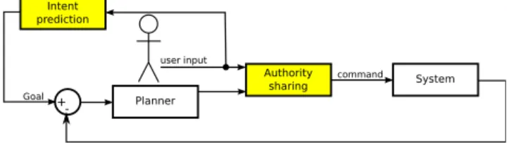
There already exist some applications involving path planners with human interactions (robot tele-operation, semi-autonomous vehicles, virtual environment explo-ration,...). These applications allow us to identify two as-pects in control sharing:
+-Goal command System Authority sharing user input Intent prediction Planner
Figure 1: Sharing control model in semi-automated sys-tems (yellow boxes are responsible for the control shar-ing)
• Authority sharing: it aims at defining how the au-thority on the system is shared between automatic planner and human. To deal with this issue, differ-ent strategies can be found in the literature. The use of virtual fixtures [21], authority switched to robot for fine motion operations [2], authority progres-sively transferred to robot while reaching the goal [23], for an anthropomorphic robot, Cartesian (posi-tion and orienta(posi-tion of end effector) control by user and joint control by planner [24]. The authority shar-ing through haptic devices were studied for semi-autonomous vehicles driving. In this case, from the horse riding experience, [13] suggests to use an hap-tic interface with a H-mode to perceive users involve-ment and allocate the authority according to it (the more the user is involved, the more authority he has). • Intent prediction: it aims at predicting the intent of the human to define the goal of an automatic con-troller and so to assist the human performing the task. These techniques are strongly based on behav-ior or trajectory recognition [1, 10, 18, 25], on mini-mum jerk criterion [23], on model predictive control [4, 19]. Dragan also recently proposed to find the targeted goal among a set of potential ones from the current movement direction [9].
We summarize these two control sharing aspects in Fig 1 where the yellow boxes illustrate the control sharing. These techniques allow involving human and automatic planning system to perform a task. However, the users ac-tions do not affect the automatic planner strategy to com-pute the path.
Interactive planning Pla nner co m p utati o nal l o a d
User cognitive load
Autom atic planni ng Proba bilistic p lanni ng wi th global appro ach (real ti me pla nner) Proba bilistic p lanni ng driven b y the user (IRRT) Local planni ng Manua l planni ng
Figure 2: Computational vs cognitive load for interactive planning
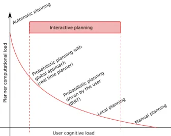
2.3 Interactive path planning
Some works propose collaboration between a human op-erator and an automatic planner in the path planning pro-cess. The simpler one [16] uses a potential field strategy. An attractive field to the goal is computed and used to guide the user through a haptic device. Another interac-tive planner from [16] guides the user along a computed trajectory. To compute this trajectory in real time, a cell decomposition of the free space is used to define a 3D tunnel. Then a RDT algorithm computes a path within this 3D tunnel. The whole trajectory computation pro-cess is restarted if user goes away the proposed trajec-tory. Finally, an interactive planner build from a proba-bilistic strategy [22] uses the users action to constraint the random sampling of the configuration space in the RRT growing.
These three planners do not involve the human user in the same way. The first one gives a strong responsibil-ity to the user (its up to him to deal with the obstacles and to avoid collisions). The second one suggests a whole trajectory the user can go away from to restart the whole planning process. The last one allows the user to point a direction that gives to the planner a preferred direction to explore. These differences of roles induce different com-putational load for the planner and cognitive load for the user as illustrated in Fig 2.
3 Proposed interactive planner
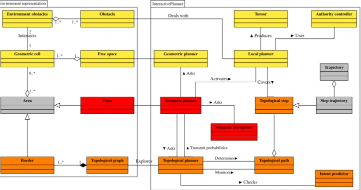
This section presents the concepts of the strategy used in the interactive planner shown in the Fig 3 where colors are linked to the environment and planning layers: yellow for geometry, orange for topology and red for semantics. The concepts used are illustrated here with 2D illustrations for clarity, but the model stands identical for 3D simulations. We argue that involving semantic and topological as-pects in path planning in addition to the common geomet-ric ones allows adapting the planning strategy to the local complexity of the environment. To deal with it, a coarse planning is performed first using semantic and topological information. Then, heavy geometric path planning strate-gies are used merely locally, (according to the place com-plexity). This allows us to plan path in real time (without disturbing users immersion in the VR simulation), and to take into account users action while performing the task to interactively update the planned path.
3.1 Environment representation
The environment example given in Fig 4.a to illustrate the concepts is made of a square workspace cluttered by 3 fixed obstacles (O1to O3) and 1 moving obstacle (O4).
The semantic layer of environment representation given in Fig 3 is made of Places. A Place is identified (Fig 4.b) taking into account only the static obstacles to build a static representation of the environment. Semantic at-tributes are assigned to the Places to describe their com-plexity (size, shape, cluttering,...) for path planning.
The topological layer connects the Places through Bor-ders. A Border Bi, j represents the overlapping area of
Places Piand Pj. These Borders are then used to build the
Topological graph of the environment shown in Fig 4.c. In this Topological graph, the nodes correspond to the Borders, and the edges to Places (and so to their seman-tics). The Fig 5.a shows the distance between the Borders centers in Place P4. These distances are set to the edges
of the Topological graph as attributes (Fig 5.b for Place P4). In Fig 4.c, the Place attribute corresponding to the
edges are given in a color linked to their complexity (from (green) low to very high (red)).
The geometric environment representation consists in a geometric description of the obstacles surfaces using meshes (Obstacle and Environment obstacle). Then, a cell 3
Environment representation InteractivePlanner 1..* 1..* 1 2 1 1..* 1..* 0..* 1 1..* H Asks I Asks DeterminesI N Asks MonitorsI N Transmit probabilities Environment obstacles Obstacle
Geometric cell
Intersects
Free space
Area Place
Border Topological graph
Semantic planner
Topological planner
Semantic interpreter
Topological path Topological step Geometric planner Local planner
ActivatesI CoversH Authority controller I Uses Torsor N Produces Trajectory Step trajectory Intent predictor I Checks Explores Deals with
Figure 2: UML Domain model of environment representation and interactive planner.
⇥
⇥
⇥
⇥
d
1d
2d
3d
4d
5d
6B
1,6B
4,6B
4,8B
2,8B
3,9B
3,10B
4,9B
4,10d
1P
8P
6P
9P
10d
2d
3d
4d
6d
5a.Place P
4distances.
b.Place P
4topological graph.
Figure 4: Topological graph building for place P
4.
in 3D) (Fig. 3.d).
This muli-layer environment model is built as
given in algorithm 1. First (line 2), the 3D mesh
of environment Objects are loaded. Second (line 3),
the Free space decomposition is computed. Third
(line 4), the free space decomposition is used to
iden-tify the place. Fourth (line 5), the Places found are
used to define the Borders. Then (line 6), the Borders
are connected building the Topological graph. Last
(line 7), semantic attributes are set to the Places.
Algorithm 1: build environment model
1
begin
2
load Objects 3D Meshes ;
3
build Free space decomposition ;
4
build Places ;
5
build Borders ;
6
build Topological graph ;
7
assign attributes to Places ;
3.2 Planning aspects
According to these environment models, the planning
process is split in two stages: the coarse planning
in-volving semantic and topological layers and the fine
planning involving semantic and geometric layers
3.2.1 Coarse planning
To adapt the geometric planning strategy to local
complexity, the whole path is split in steps. A step
refers to a place of environment representation. A step
also refers to a border to reach to fulfill the step. The
geometric planning strategy is thus chosen according
to the semantic information of step’s place.
Algorithm 2: coarse planning
1
begin
2
update Topological graph (start & goal) nodes ;
3
update Topological graph’s costs ;
4
explore Topological graph ;
5
build Topological path and Topological steps ;
6
for Topological step 2 Topological path do
7
define milestone for Topological step ;
Algorithm 2 describes this stage. Two nodes
cor-responding to start (S) and goal (G) configurations
are added to the topological graph (line 2). To direct
the graph exploration the Semantic planner, thanks to
the Semantic interpreter, assigns costs (C) to graph’s
nodes (n
i, j) and edges (e
k) (line 3). These costs are
Figure 3: UML domain model of environment representation and interactive planner (red classes handle semantics, orange classes handle topology, and yellow classes handle geometry)
O1 O2 O3 O4 not comple x not comple x complex complex very complex very complex very comple x comple x cluttered not complex fix ed fix ed fixed mo ving
a.2D environment. b.Semantic model.
B1,5 B2,7 B1,6 B2,8 B3,5 B3,7 B4,6 B4,8 B3,9 B3,10 B4,9 B4,10 P1 P2 P3 P4 P5 P7 P8 P6 P9 P10 P3 P3 P3 P3 P4 P4 P4 P4
c.Topological graph. d.Free space decomposition. Fig. 1. Different perceptions of environment for user and planner.
S G B1,5 B2,7 B1,6 B2,8 B3,5 B3,7 B4,6 B4,8 B3,9 B3,10 B4,9 B4,10 P1 P1 P1 P2 P3 P4 P5 P7 P8 P6 P9 P10 P3 P3 P3 P3 P4 P4 P4 P4 P2 P2 S G M M M M M M M M M M
a.Topological path. b.Geometrical path.
Fig. 2. Topological and geometrical paths.
C. Interactions and control sharing
The automatic path planner described above assists a human operator immersed in VR simulation to perform assembly tasks. Thus we propose novel interaction modes to guide the user, but also, to let the user suggest new directions to the automatic path planner. The interaction ergonomics have been improved thanks to control sharing techniques inspired from semi-autonomous vehicle driving (authority sharing) and robot tele-operation (intent prediction).
1) Interactions: Two interaction modes allow the au-tomatic path planner and the immersed human operator collaborating while performing the assembly task:
• the trajectory defined by the automatic path planner is
used to guide the user through a haptic device. To do so, the guidance pulling the human operator is computed from a linear interpolation toward the next geometrical milestone (the next geometrical milestone being updated as the task is being performed Figure 3.a).
• the movements performed by the human operator are
used to detect if he goes away the proposed trajectory at the topological layer. If so, his intent is predicted and
G C C !g M M M M M M M M M M C C C C C C C C C C C C C C C CC GG !g M M M M M M M M M M C C C C C M M M M M M C M M C
a.Guidance update. b.Path re-planning.
Fig. 3. Planning interaction modes
used to re-plan a new path (Figure 3.b).
2) Authority sharing: The H-mode proposed in [2] has been adapted to dynamically balance the authority of the automatic path planner (by modulating the guidance norm) according to the user involvement. This allows having a strong guidance while the operator is following it, and a reduced one when he is exploring other paths.
3) Intent prediction: The intent prediction from [3] in-spired us to define a way to predict user’s intent at topologi-cal level and then use it to guide a coarse re-planning toward the user’s preferred path.
IV. CONCLUSION
This paper presents a novel architecture for interactive path planning in VR simulations. This architecture is based on multi-layer environment model and planner. This architecture involves semantic topological and geometric information while path planning traditionally handle geometric informa-tion only. The contribuinforma-tion of such architecture is two-fold:
• First, it provides the user with real-time path planning
assistance thanks to the semantic and topological layers by splitting the path in steps and then by adapting the geometric planning strategy to the local complexity of each step.
• Second, it integrates efficiently a human in the loop:
real-time re-planning is computed based on operator’s intent and motion control is shared by the user and the planner. Moreover, the user capabilities are used to overcome the automatic path planner weaknesses.
REFERENCES
[1] N. Ladev`eze, J.-Y. Fourquet, and B. Puel, “Interactive path planning for haptic assistance in assembly tasks,” Computers & Graphics, vol. 34, no. 1, pp. 17–25, 2010.
[2] F. O. Flemisch, M. Heesen, T. Hesse, J. Kelsch, A. Schieben, and J. Beller, “Towards a dynamic balance between humans and automation: authority, ability, responsibility and control in shared and cooperative control situations,” Cognition, Technology & Work, vol. 14, no. 1, pp. 3–18, 2012.
[3] A. D. Dragan and S. S. Srinivasa, “A policy blending formalism for shared control,” International Journal of Robotics Research, 2013.
a. 2D environment b. Places and semantic information
O1 O2 O3 O4 not comple x not comple x complex complex very complex very complex very comple x comple x cluttered not complex fix ed fix ed fixed mo ving
a.2D environment. b.Semantic model.
B1,5 B2,7 B1,6 B2,8 B3,5 B3,7 B4,6 B4,8 B3,9 B3,10 B4,9 B4,10 P1 P2 P3 P4 P5 P7 P8 P6 P9 P10 P3 P3 P3 P3 P4 P4 P4 P4
c.Topological graph. d.Free space decomposition. Fig. 1. Different perceptions of environment for user and planner.
S G B1,5 B2,7 B1,6 B2,8 B3,5 B3,7 B4,6 B4,8 B3,9 B3,10 B4,9 B4,10 P1 P1 P1 P2 P3 P4 P5 P7 P8 P6 P9 P10 P3 P3 P3 P3 P4 P4 P4 P4 P2 P2 S G M M M M M M M M M M
a.Topological path. b.Geometrical path.
Fig. 2. Topological and geometrical paths.
C. Interactions and control sharing
The automatic path planner described above assists a human operator immersed in VR simulation to perform assembly tasks. Thus we propose novel interaction modes to guide the user, but also, to let the user suggest new directions to the automatic path planner. The interaction ergonomics have been improved thanks to control sharing techniques inspired from semi-autonomous vehicle driving (authority sharing) and robot tele-operation (intent prediction).
1) Interactions: Two interaction modes allow the au-tomatic path planner and the immersed human operator collaborating while performing the assembly task:
• the trajectory defined by the automatic path planner is
used to guide the user through a haptic device. To do so, the guidance pulling the human operator is computed from a linear interpolation toward the next geometrical milestone (the next geometrical milestone being updated as the task is being performed Figure 3.a).
• the movements performed by the human operator are
used to detect if he goes away the proposed trajectory at the topological layer. If so, his intent is predicted and
G C C !g M M M M M M M M M M C C C C C C C C C C C C C C C CC GG !g M M M M M M M M M M C C C C C M M M M M M C M M C
a.Guidance update. b.Path re-planning.
Fig. 3. Planning interaction modes
used to re-plan a new path (Figure 3.b).
2) Authority sharing: The H-mode proposed in [2] has been adapted to dynamically balance the authority of the automatic path planner (by modulating the guidance norm) according to the user involvement. This allows having a strong guidance while the operator is following it, and a reduced one when he is exploring other paths.
3) Intent prediction: The intent prediction from [3] in-spired us to define a way to predict user’s intent at topologi-cal level and then use it to guide a coarse re-planning toward the user’s preferred path.
IV. CONCLUSION
This paper presents a novel architecture for interactive path planning in VR simulations. This architecture is based on multi-layer environment model and planner. This architecture involves semantic topological and geometric information while path planning traditionally handle geometric informa-tion only. The contribuinforma-tion of such architecture is two-fold:
• First, it provides the user with real-time path planning
assistance thanks to the semantic and topological layers by splitting the path in steps and then by adapting the geometric planning strategy to the local complexity of each step.
• Second, it integrates efficiently a human in the loop:
real-time re-planning is computed based on operator’s intent and motion control is shared by the user and the planner. Moreover, the user capabilities are used to overcome the automatic path planner weaknesses.
REFERENCES
[1] N. Ladev`eze, J.-Y. Fourquet, and B. Puel, “Interactive path planning for haptic assistance in assembly tasks,” Computers & Graphics, vol. 34, no. 1, pp. 17–25, 2010.
[2] F. O. Flemisch, M. Heesen, T. Hesse, J. Kelsch, A. Schieben, and J. Beller, “Towards a dynamic balance between humans and automation: authority, ability, responsibility and control in shared and cooperative control situations,” Cognition, Technology & Work, vol. 14, no. 1, pp. 3–18, 2012.
[3] A. D. Dragan and S. S. Srinivasa, “A policy blending formalism for shared control,” International Journal of Robotics Research, 2013.
O1 O2 O3 O4 not comple x not comple x complex complex very complex very complex very comple x comple x cluttered not complex fix ed fix ed fixed mo ving
a.2D environment. b.Semantic model.
B1,5 B2,7 B1,6 B2,8 B3,5 B3,7 B4,6 B4,8 B3,9 B3,10 B4,9 B4,10 P1 P2 P3 P4 P5 P7 P8 P6 P9 P10 P3 P3 P3 P3 P4 P4 P4 P4
c.Topological graph. d.Free space decomposition. Fig. 1. Different perceptions of environment for user and planner.
S G B1,5 B2,7 B1,6 B2,8 B3,5 B3,7 B4,6 B4,8 B3,9 B3,10 B4,9 B4,10 P1 P1 P1 P2 P3 P4 P5 P7 P8 P6 P9 P10 P3 P3 P3 P3 P4 P4 P4 P4 P2 P2 S G M M M M M M M M M M
a.Topological path. b.Geometrical path.
Fig. 2. Topological and geometrical paths.
C. Interactions and control sharing
The automatic path planner described above assists a human operator immersed in VR simulation to perform assembly tasks. Thus we propose novel interaction modes to guide the user, but also, to let the user suggest new directions to the automatic path planner. The interaction ergonomics have been improved thanks to control sharing techniques inspired from semi-autonomous vehicle driving (authority sharing) and robot tele-operation (intent prediction).
1) Interactions: Two interaction modes allow the au-tomatic path planner and the immersed human operator collaborating while performing the assembly task:
• the trajectory defined by the automatic path planner is
used to guide the user through a haptic device. To do so, the guidance pulling the human operator is computed from a linear interpolation toward the next geometrical milestone (the next geometrical milestone being updated as the task is being performed Figure 3.a).
• the movements performed by the human operator are
used to detect if he goes away the proposed trajectory at the topological layer. If so, his intent is predicted and
G C C !g M M M M M M M M M M C C C C C C C C C C C C C C C CC GG !g M M M M M M M M M M C C C C C M M M M M M C M M C
a.Guidance update. b.Path re-planning.
Fig. 3. Planning interaction modes used to re-plan a new path (Figure 3.b).
2) Authority sharing: The H-mode proposed in [2] has been adapted to dynamically balance the authority of the automatic path planner (by modulating the guidance norm) according to the user involvement. This allows having a strong guidance while the operator is following it, and a reduced one when he is exploring other paths.
3) Intent prediction: The intent prediction from [3] in-spired us to define a way to predict user’s intent at topologi-cal level and then use it to guide a coarse re-planning toward the user’s preferred path.
IV. CONCLUSION
This paper presents a novel architecture for interactive path planning in VR simulations. This architecture is based on multi-layer environment model and planner. This architecture involves semantic topological and geometric information while path planning traditionally handle geometric informa-tion only. The contribuinforma-tion of such architecture is two-fold:
• First, it provides the user with real-time path planning
assistance thanks to the semantic and topological layers by splitting the path in steps and then by adapting the geometric planning strategy to the local complexity of each step.
• Second, it integrates efficiently a human in the loop:
real-time re-planning is computed based on operator’s intent and motion control is shared by the user and the planner. Moreover, the user capabilities are used to overcome the automatic path planner weaknesses.
REFERENCES
[1] N. Ladev`eze, J.-Y. Fourquet, and B. Puel, “Interactive path planning for haptic assistance in assembly tasks,” Computers & Graphics, vol. 34, no. 1, pp. 17–25, 2010.
[2] F. O. Flemisch, M. Heesen, T. Hesse, J. Kelsch, A. Schieben, and J. Beller, “Towards a dynamic balance between humans and automation: authority, ability, responsibility and control in shared and cooperative control situations,” Cognition, Technology & Work, vol. 14, no. 1, pp. 3–18, 2012.
[3] A. D. Dragan and S. S. Srinivasa, “A policy blending formalism for shared control,” International Journal of Robotics Research, 2013.
c. Topological graph d. Free space decomposition
Figure 4: Different representations of the environment
Environment representation InteractivePlanner
1..* 1 2 1 1..* 1..* 0..* 1 1..* Asks
Asks Transmit probabilities Determines Monitors
Asks
Environment Object
Geometric cell Freespace
Area Place
Border Topological graph
Intersects
Torsor
Geometric planner
Local planner
Semantic planner
Topological planner Topological path
Topological step Semantic interpretor Activates Covers Produces Trajectory Step trajectory Authority controller Intent predictor Checks Uses Explores Dealswith 1..*
Fig. 3. UML Domain model of environment representation and interactive planner.
O1 O2 O3 O4 P1 P2 P5 P7 P8 P6 P9 P10 P3 P4
a.2D environment. b.Environment’s places.
B1,5 B2,7 B1,6 B2,8 B3,5 B3,7 B4,6 B4,8 B3,9 B3,10 B4,9 B4,10 P1 P2 P3 P4 P5 P7 P8 P6 P9 P10 P3 P3 P3 P3 P4 P4 P4 P4
c.Topological graph. d.Free space decomposition.
Fig. 4. Different perceptions of environment for user and planner.
The semantic information is attached to places. Semantic
attributes are assigned to the places to describe their
com-plexity (size, shape, cluttering,...) for path planning.
The geometric environment representation consists in a
geometric description of the environment’s objectsand a cell
decomposition of the Free space. The Objects are described
with meshes (Object. The free space decomposition is a
quadtree (an octree in 3D) to describe the 2D (3D) free space
(Fig. 4.d).
This muli-layer environment model is build as given in
the algorithm 1. First (line 2), the 3D mesh of
environ-ment Objects are loaded. Second (line 3), the Free space
decomposition is computed. Third (line 4), the free space
⇥ ⇥ ⇥ ⇥ d1 d2 d3 d4 d5 d6 B1,6 B4,6 B4,8 B2,8 B3,9 B3,10 B4,9 B4,10 d1 P8 P6 P9 P10 d2 d3 d4 d6 d5
a.Place P4 distances. b.Place P4 topological graph.
Fig. 5. Topological graph building for place P4.
decomposition is used to identify the place. Fourth (line 5),
the Places found are used to define the Borders. Then
(line 6), the Borders are connected building the Topological
graph. Last (line 7), semantic attributes are set to the places.
Algorithm 1: build environment model
1 begin
2 load Objects 3D Meshes ;
3 build Free space decomposition ;
4 build Places ;
5 build Borders ;
6 build Topological graph ;
7 assign attributes to Places ;
B. Planning aspects
According to these environment models, the planning
process is split in two stages: the coarse planning
involv-ing semantic and topological layers and the fine planninvolv-ing
involving semantic and geometric layers
1) Coarse planning: To adapt the geometric planning
strategy to local complexity, the whole path is split in steps.
A step refers to a place of environment representation. A
step also refers to a border to reach to fulfill the step. The
a. Distances in place P4 b.Topological graph of place P4
Figure 5: Topological graph of place P4
decomposition of the environment (Free space and Geo-metric Cell) is made with a quadtree (an octree in 3D) to describe the 2D (3D) free space (Fig 4.d).
3.2 Planning aspects
According to these environment models, the planning pro-cess is split in two stages: the coarse planning involving semantic and topological layers and the fine planning in-volving semantic and geometric layers.
3.2.1 Coarse planning
To adapt the geometric planning strategy to local com-plexity, the whole path is split in steps. A step refers to a Place of environment representation. A step also refers to a Border to reach to fulfill the step. The geometric planning strategy is thus chosen according to the seman-tic information of the steps place. To run this planning stage, two nodes corresponding to start and goal configu-rations are added to the Topological graph. To direct the graph exploration the Semantic planner, based on the Se-mantic interpreter, assigns costs (C) to graphs nodes (ni, j)
and edges (ek) accordingly to the semantic information of
involved places (1).
Cni, j=f (sem(Pi),sem(Pj)) Cek=f (dk,sem(P(ek)))
(1) Where sem(P) is the semantic information of Place P, ekis a graphs edge, dkits distance attribute and P(ek) its
place attribute; ni, j is the node linked to the border Bi, j
between Piand Pj.
These costs make the cost of a path (Cpath) computation
possible (2). Cpath=
∑
ni, j∈path Cni, j+∑
ek∈path Cek (2)Then the graph is explored by the Topological plan-ner using a Dijkstra algorithm [8] to find the less expen-sive Topological path between start and goal nodes. This Topological path is used to split the trajectory in Topolog-ical steps, each step corresponding to a Place to cross (a edge of Topological path) and a Border to reach (a node of Topological path).
3.2.2 Fine planning
This planning stage consists in finding the concrete ge-ometrical path. To do so, each Topological step is used to define a milestone configuration within the border to reach. Then, accordingly to the semantic information of the Place to cross, we adapt the geometric path planning strategy. Depending on the cluttering semantic attribute, an RRT algorithm can be ran on the place to set interme-diate milestones within the step. When all the milestones have been defined, the Local planner guides the user to-ward the next milestone. This one compute a Torsor from a linear interpolation applied on a haptic device.
3.2.3 Coarse and fine planning organization
The coarse and fine planning are used to manage the whole planning. The Topological path and its steps are concepts allowing the different planning layers to share the information. Once the Topological path found and the Topological steps defined, the steps information is used by the Semantic planner to accurately set the geometric layer.
3.2.4 Process monitoring
While the user is performing the task, he is guided to-ward the next milestone configuration through the hap-tic device. This next milestone must be updated while the user is progressing along the path. On the geometric layer, the next milestone is set to the Local planner for the guidance computation when the current one is consid-ered as reached. The goal is considconsid-ered as reached when the distance between the goal and the current position is smaller than θd. On the topological layer, the milestone is
a Border, so even if the user is guided toward a geomet-ric configuration set within the Border, the milestone is considered as reached as soon as the user enters the Bor-der. Thus, when the target Border is reached, the next Topological step is used to set the Local planner and to monitor the remaining process.
3.3 Control sharing aspects
The planner provides user with a guidance Torsor through the haptic device used for object manipulation. The Local planner computes this guidance Torsor. For each layer of
Table 2: Interaction means on the different layers
Authority sharing Intent prediction
Semantic layer
Learn from users action new seman-tics information or means to deal with them to accurately set the topological and geometric plan-ners
Interpret planning query expressed in natural language (assemble this part on this one, bring this object on this one,...)
Topological layer
Check if user
agrees the
pro-posed topological
path. Trying to
predict his in- tents on the topological layer (which place he is targeting)
Learn the kind of paces the user prefers to cross to advantage them during the topolog-ical path planning process
Geometric layer
Dynamically bal-ance the authority
on the object
manipulation (be-tween hu- man and
automatic
plan-ner) by modulating the au- tomatic
planner guidance
force
Find the targeted next place to rede-fine the geo- metric planner goal
such planner architecture, specific ways to share control can be envisaged as shown in Table 2.
In Table 2 it appears that the intent prediction for the geometric layer is directly linked to the authority sharing of topological layer. Indeed, within a Place, the set of potential goals to get out of this Place is made of the cor-responding Borders. The intent prediction is made with geometric movement and geometric information on Bor-ders. The re-planning is made by the Topological planner for a new Topological path definition.
The same applies for the intent prediction of the topo-logical layer and the authority sharing of the semantic layer. Cost functions of (1) may be learned from the Places the user prefers to cross. These preferred Places 6
attributes can be identified from all the re-planning done due to users action. The new cost value defined with these functions will thus change all the incoming topological re-planning.
The control sharing of the proposed planning architec-ture is focused on the geometric and topological layers. A H-mode from [13] had been implemented for geometric authority control. An intent prediction inspired from [9] had also been set to make the topological path re-planning available.
4 Implementation
4.1 VR platform
We implemented this architecture in VirtoolsTM4.1
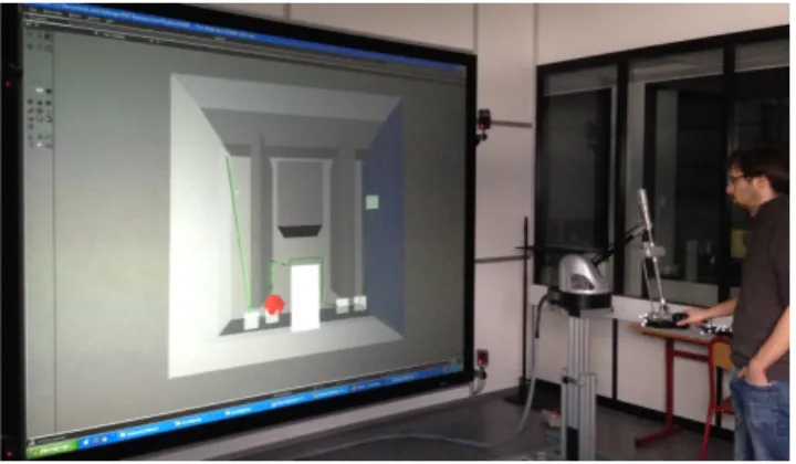
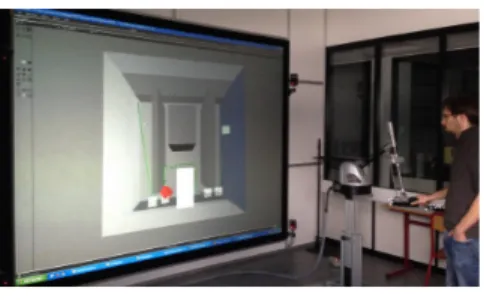
soft-ware through libraries developed in C++ language. We developed 3 distinct libraries: 2 autonomous libraries cor-responding to environment model and path planner and an interface library. The VR devices used are a large 3D display to immerse interacting user into the environment; a motion capture system to consider user’s point of view for scene display and to allow him to visually explore the environment; and a haptic arm to manipulate the objects. Fig 6 shows the corresponding VR platform. The devices used in these simulations are:
• A large passive stereo-visualization screen • A ART motion capture system ARTTRACK2 • A Haption virtuose 6D 35-45 haptic arm
4.2 Environment representation built
The environment model is implemented in a dedicated li-brary interfaced to VirtoolsTM with a specific library.
The environment representation we use is made of 4 models:
• The objects of the environment represented through meshes and positioning frames. We distinguish among them the fixed ones and the moving ones us-ing a flag parameter to be able to exclude the movus-ing ones while identifying the places (static mapping of the environment). All the objects of the environment
Figure 6: Simulation on VR platform
can have semantic attributes assigned. This part is strongly based on the CGAL project [6].
• The free space description through an octree decom-position of the 3D scene (in this case also, the nodes colliding with fixed object are distinguished from those colliding with only moving objects)
• The topological graph to model the places connectiv-ity (the graphs nodes are the borders, and the edges the places)
• The set of places and their borders. We defined some procedure to automatically identify the places from the octree structure and the semantic information at-tachment is manually made, choosing for each place the right attributes among a set of available ones. One attribute is automatically set: cluttered if the place contain moving obstacles
The attributes available in our simulations allow de-scribing the level of complexity of a place: low, average, high, and very high.
4.3 Planner implementation
The planner is also implemented in a dedicated library and interfaced to VirtoolsTM using the same interface library
used to interface the environment. 7
4.3.1 Planning classes
Four classes have been defined corresponding to the four planners. Each of these planner classes deals with an envi-ronment model. The Local Planner provides the user with the guidance. The Geometric planner finds, if necessary, a geometrical path to cross a cluttered Places. The Topo-logical planner explores the TopoTopo-logical graph to build the path and the steps managed by the local and the ge-ometric planners. The Semantic planner coordinates the whole planning process, asking the Topological planner for the Topological path and planning which strategy will be used on the geometric layer. For the weights computa-tion, we defined the function of (1) assigning the weights as given in (3). Cni, j= Ccomplexity 2 Cek=dk.Ccomplexity (3)
Where Ccomplexity is set according to the involved
Places’ complexity to 0, 0.5, 1 and 5 for low, average, high and very high complexity.
4.3.2 Control sharing classes
Two main classes improve the planner for the control sharing. The first one is correspond to the Authority con-troller. It aims at modulating the guidance norm corre-sponding to user involvement. It allows user to feel free when he is exploring for others ways. The second one is the Intent predictor. It detects the user intents to com-pute a new Topological path when the user goes away the proposed one. These two classes and there computation are strongly based on the instantaneous movement com-puted from the recorded trajectory in Trajectory and Step trajectory objects.
5 Simulation and results
We have implemented the following simulations on our VR platform (Fig. 7). The VR devices used here are a large screen using passive stereoscopy for the 3D visual-ization and immersion, an AR Track system for the user view-point capture and a Virtuose 6D 35-45 haptic device for the part handling.
Figure 7: Simulation on VR platform
The first simulation is a 3D instance of the 2D example used to illustrate the principles of our planning strategy in section 3. It has been used for development and allowed to test the collaboration of the planners. The second sim-ulation shows a richer semantics of the environment (se-mantic attributes that describe the shape of objects and places). This allows showing how the control of the plan-ning process, using the semantic information, increases the reliability of the planned path while reducing the pro-cessing time.
5.1 Semantic control and control sharing
application
5.1.1 Simulation scene
To test the multi-layer structure on the laboratory’s VR platform, the environment used is a 3D instance of the environment given in section 3. This environment is a cubic workspace with four obstacles cluttering the scene (3 fixed and 1 moving). Different environment config-urations have been tested moving the fixed obstacles to
change the complex passages locations (O1 and O2 are
moved vertically and O3horizontally). The
correspond-ing topological graphs are given in Fig. 8. This figure also illustrates the planning query in these environments. It aims at bringing a virtual object from a start point S in place P1to a goal point G in place P2. The topological
paths found by the topological planner are also displayed in bold blue lines in the topological graphs.
S G B1,5 B2,7 B1,6 B2,8 B3,5 B3,7 B4,6 B4,8 B3,9 B3,10 B4,9 B4,10 P1 P1 P1 P2 P3 P4 P5 P7 P8 P6 P9 P10 P3 P3 P3 P3 P4 P4 P4 P4 P2 P2 S G T1,5 T2,7 T1,6 T2,8 T3,5 T3,7 T4,6 T4,8 T3,9 T3,10 T4,9 T4,10 P1 P1 P1 P2 P3 P4 P5 P7 P8 P6 P9 P10 P3 P3 P3 P3 P4 P4 P4 P4 P2 P2 a.Environment 1. b.Environment 2. S G T1,5 T2,7 T1,6 T2,8 T3,5 T3,7 T4,6 T4,8 T3,9 T3,10 T4,9 T4,10 P1 P1 P1 P2 P3 P4 P5 P7 P8 P6 P9 P10 P3 P3 P3 P3 P4 P4 P4 P4 P2 P2 S G T1,5 T2,7 T1,6 T2,8 T3,5 T3,7 T4,6 T4,8 T3,9 T3,10 T4,9 T4,10 P1 P1 P1 P2 P3 P4 P5 P7 P8 P6 P9 P10 P3 P3 P3 P3 P4 P4 P4 P4 P2 P2 c.Environment 3. d.Environment 4.
Figure 9: Experimental environments.
5.1 First simulation
5.1.1 Simulation scene
To test the multi-layer structure on the laboratory’s VR platform, the environment used is a 3D instance of the environment described in section 3. This en-vironment is a cubic workspace with four obstacles cluttering the scene (3 fixed and 1 moving). Different environment configurations have been tested moving the fixed obstacles to change the complex passages
lo-cations (O1and O2are moved vertically and O3
hor-izontally). The corresponding topological graphs are given in Fig. 9. This figure also illustrates the plan-ning query in these environments. It aims at
bring-ing a piece from a start point S in place P1to a goal
point G in place P2. The topological paths found by
the topological planner are also displayed in bold blue lines in the topological graphs.
5.1.2 Path planning
Fig. 10 shows the real path computed in the environ-ment illustrated in Fig. 9. The object to move is the red cube and the targeted goal is the green one. The
path is displayed in green. The paths on place P3
avoid mobile obstacle O4thanks to the A* algorithm
performed on this cluttered place. To find such paths, the computational time for the Dijkstra algorithm in the topological graph was about 1ms, and the A* al-gorithm when necessary to cross the cluttered place took from 50ms to 750ms depending on the path to find. Thus, the whole path is find in less than 1s when using the A* algorithm alone without any semantics
a.Environment 1. b.Environment 2.
c.Environment 3. d.Environment 4.
Figure 10: Planning results.
a.Re-planning in step 1. b.Re-planning in step 3. Figure 11: Topological re-planning in environment 1. or topology planning process takes about 3.5s without avoiding complex passages (in this case the past com-puted is the shortest but not the easiest to perform). 5.1.3 Path re-planning
Fig. 11 illustrates the topological re-planning includ-ing real-time detection of user’s intent. In Fig. 11.a, in the first step, the user seems to prefer the narrow pas-sage. Detecting it, the topological path is recomputed taking into account this intent. In Fig. 11.b, the user doesn’t follow the guidance along the A* path in the third step. Thus, the topological planner computes a new topological path. The path re-planning including A* process is done in less than 150ms in this case.
5.2 Second simulation
5.2.1 Simulation scene
Our simulation scene (see Fig. 12) is made of a cubic workspace divided in three large places by two walls. The wall in the foreground is an obstacle with four holes. Each hole has a characteristic shape (square,
S G B1,5 B2,7 B1,6 B2,8 B3,5 B3,7 B4,6 B4,8 B3,9 B3,10 B4,9 B4,10 P1 P1 P1 P2 P3 P4 P5 P7 P8 P6 P9 P10 P3 P3 P3 P3 P4 P4 P4 P4 P2 P2 S G T1,5 T2,7 T1,6 T2,8 T3,5 T3,7 T4,6 T4,8 T3,9 T3,10 T4,9 T4,10 P1 P1 P1 P2 P3 P4 P5 P7 P8 P6 P9 P10 P3 P3 P3 P3 P4 P4 P4 P4 P2 P2 a.Environment 1. b.Environment 2. S G T1,5 T2,7 T1,6 T2,8 T3,5 T3,7 T4,6 T4,8 T3,9 T3,10 T4,9 T4,10 P1 P1 P1 P2 P3 P4 P5 P7 P8 P6 P9 P10 P3 P3 P3 P3 P4 P4 P4 P4 P2 P2 S G T1,5 T2,7 T1,6 T2,8 T3,5 T3,7 T4,6 T4,8 T3,9 T3,10 T4,9 T4,10 P1 P1 P1 P2 P3 P4 P5 P7 P8 P6 P9 P10 P3 P3 P3 P3 P4 P4 P4 P4 P2 P2 c.Environment 3. d.Environment 4.
Figure 9: Experimental environments.
5.1 First simulation
5.1.1 Simulation scene
To test the multi-layer structure on the laboratory’s VR platform, the environment used is a 3D instance of the environment described in section 3. This en-vironment is a cubic workspace with four obstacles cluttering the scene (3 fixed and 1 moving). Different environment configurations have been tested moving the fixed obstacles to change the complex passages
lo-cations (O1and O2are moved vertically and O3
hor-izontally). The corresponding topological graphs are given in Fig. 9. This figure also illustrates the plan-ning query in these environments. It aims at
bring-ing a piece from a start point S in place P1 to a goal
point G in place P2. The topological paths found by
the topological planner are also displayed in bold blue lines in the topological graphs.
5.1.2 Path planning
Fig. 10 shows the real path computed in the environ-ment illustrated in Fig. 9. The object to move is the red cube and the targeted goal is the green one. The
path is displayed in green. The paths on place P3
avoid mobile obstacle O4thanks to the A* algorithm
performed on this cluttered place. To find such paths, the computational time for the Dijkstra algorithm in the topological graph was about 1ms, and the A* al-gorithm when necessary to cross the cluttered place took from 50ms to 750ms depending on the path to find. Thus, the whole path is find in less than 1s when using the A* algorithm alone without any semantics
a.Environment 1. b.Environment 2.
c.Environment 3. d.Environment 4.
Figure 10: Planning results.
a.Re-planning in step 1. b.Re-planning in step 3. Figure 11: Topological re-planning in environment 1. or topology planning process takes about 3.5s without avoiding complex passages (in this case the past com-puted is the shortest but not the easiest to perform). 5.1.3 Path re-planning
Fig. 11 illustrates the topological re-planning includ-ing real-time detection of user’s intent. In Fig. 11.a, in the first step, the user seems to prefer the narrow pas-sage. Detecting it, the topological path is recomputed taking into account this intent. In Fig. 11.b, the user doesn’t follow the guidance along the A* path in the third step. Thus, the topological planner computes a new topological path. The path re-planning including A* process is done in less than 150ms in this case.
5.2 Second simulation
5.2.1 Simulation scene
Our simulation scene (see Fig. 12) is made of a cubic workspace divided in three large places by two walls. The wall in the foreground is an obstacle with four holes. Each hole has a characteristic shape (square,
a.Environment 1 b.Environment 2 S G B1,5 B2,7 B1,6 B2,8 B3,5 B3,7 B4,6 B4,8 B3,9 B3,10 B4,9 B4,10 P1 P1 P1 P2 P3 P4 P5 P7 P8 P6 P9 P10 P3 P3 P3 P3 P4 P4 P4 P4 P2 P2 S G T1,5 T2,7 T1,6 T2,8 T3,5 T3,7 T4,6 T4,8 T3,9 T3,10 T4,9 T4,10 P1 P1 P1 P2 P3 P4 P5 P7 P8 P6 P9 P10 P3 P3 P3 P3 P4 P4 P4 P4 P2 P2 a.Environment 1. b.Environment 2. S G T1,5 T2,7 T1,6 T2,8 T3,5 T3,7 T4,6 T4,8 T3,9 T3,10 T4,9 T4,10 P1 P1 P1 P2 P3 P4 P5 P7 P8 P6 P9 P10 P3 P3 P3 P3 P4 P4 P4 P4 P2 P2 S G T1,5 T2,7 T1,6 T2,8 T3,5 T3,7 T4,6 T4,8 T3,9 T3,10 T4,9 T4,10 P1 P1 P1 P2 P3 P4 P5 P7 P8 P6 P9 P10 P3 P3 P3 P3 P4 P4 P4 P4 P2 P2 c.Environment 3. d.Environment 4.
Figure 9: Experimental environments.
5.1 First simulation
5.1.1 Simulation scene
To test the multi-layer structure on the laboratory’s VR platform, the environment used is a 3D instance of the environment described in section 3. This en-vironment is a cubic workspace with four obstacles cluttering the scene (3 fixed and 1 moving). Different environment configurations have been tested moving the fixed obstacles to change the complex passages
lo-cations (O1and O2are moved vertically and O3
hor-izontally). The corresponding topological graphs are given in Fig. 9. This figure also illustrates the plan-ning query in these environments. It aims at
bring-ing a piece from a start point S in place P1 to a goal
point G in place P2. The topological paths found by
the topological planner are also displayed in bold blue lines in the topological graphs.
5.1.2 Path planning
Fig. 10 shows the real path computed in the environ-ment illustrated in Fig. 9. The object to move is the red cube and the targeted goal is the green one. The
path is displayed in green. The paths on place P3
avoid mobile obstacle O4thanks to the A* algorithm
performed on this cluttered place. To find such paths, the computational time for the Dijkstra algorithm in the topological graph was about 1ms, and the A* al-gorithm when necessary to cross the cluttered place took from 50ms to 750ms depending on the path to find. Thus, the whole path is find in less than 1s when using the A* algorithm alone without any semantics
a.Environment 1. b.Environment 2.
c.Environment 3. d.Environment 4.
Figure 10: Planning results.
a.Re-planning in step 1. b.Re-planning in step 3. Figure 11: Topological re-planning in environment 1. or topology planning process takes about 3.5s without avoiding complex passages (in this case the past com-puted is the shortest but not the easiest to perform). 5.1.3 Path re-planning
Fig. 11 illustrates the topological re-planning includ-ing real-time detection of user’s intent. In Fig. 11.a, in the first step, the user seems to prefer the narrow pas-sage. Detecting it, the topological path is recomputed taking into account this intent. In Fig. 11.b, the user doesn’t follow the guidance along the A* path in the third step. Thus, the topological planner computes a new topological path. The path re-planning including A* process is done in less than 150ms in this case.
5.2 Second simulation
5.2.1 Simulation scene
Our simulation scene (see Fig. 12) is made of a cubic workspace divided in three large places by two walls. The wall in the foreground is an obstacle with four holes. Each hole has a characteristic shape (square,
S G B1,5 B2,7 B1,6 B2,8 B3,5 B3,7 B4,6 B4,8 B3,9 B3,10 B4,9 B4,10 P1 P1 P1 P2 P3 P4 P5 P7 P8 P6 P9 P10 P3 P3 P3 P3 P4 P4 P4 P4 P2 P2 S G T1,5 T2,7 T1,6 T2,8 T3,5 T3,7 T4,6 T4,8 T3,9 T3,10 T4,9 T4,10 P1 P1 P1 P2 P3 P4 P5 P7 P8 P6 P9 P10 P3 P3 P3 P3 P4 P4 P4 P4 P2 P2 a.Environment 1. b.Environment 2. S G T1,5 T2,7 T1,6 T2,8 T3,5 T3,7 T4,6 T4,8 T3,9 T3,10 T4,9 T4,10 P1 P1 P1 P2 P3 P4 P5 P7 P8 P6 P9 P10 P3 P3 P3 P3 P4 P4 P4 P4 P2 P2 S G T1,5 T2,7 T1,6 T2,8 T3,5 T3,7 T4,6 T4,8 T3,9 T3,10 T4,9 T4,10 P1 P1 P1 P2 P3 P4 P5 P7 P8 P6 P9 P10 P3 P3 P3 P3 P4 P4 P4 P4 P2 P2 c.Environment 3. d.Environment 4. Figure 9: Experimental environments.
5.1 First simulation
5.1.1 Simulation scene
To test the multi-layer structure on the laboratory’s VR platform, the environment used is a 3D instance of the environment described in section 3. This en-vironment is a cubic workspace with four obstacles cluttering the scene (3 fixed and 1 moving). Different environment configurations have been tested moving the fixed obstacles to change the complex passages
lo-cations (O1and O2are moved vertically and O3
hor-izontally). The corresponding topological graphs are given in Fig. 9. This figure also illustrates the plan-ning query in these environments. It aims at
bring-ing a piece from a start point S in place P1 to a goal
point G in place P2. The topological paths found by
the topological planner are also displayed in bold blue lines in the topological graphs.
5.1.2 Path planning
Fig. 10 shows the real path computed in the environ-ment illustrated in Fig. 9. The object to move is the red cube and the targeted goal is the green one. The
path is displayed in green. The paths on place P3
avoid mobile obstacle O4thanks to the A* algorithm
performed on this cluttered place. To find such paths, the computational time for the Dijkstra algorithm in the topological graph was about 1ms, and the A* al-gorithm when necessary to cross the cluttered place took from 50ms to 750ms depending on the path to find. Thus, the whole path is find in less than 1s when using the A* algorithm alone without any semantics
a.Environment 1. b.Environment 2.
c.Environment 3. d.Environment 4. Figure 10: Planning results.
a.Re-planning in step 1. b.Re-planning in step 3. Figure 11: Topological re-planning in environment 1.
or topology planning process takes about 3.5s without avoiding complex passages (in this case the past com-puted is the shortest but not the easiest to perform). 5.1.3 Path re-planning
Fig. 11 illustrates the topological re-planning includ-ing real-time detection of user’s intent. In Fig. 11.a, in the first step, the user seems to prefer the narrow pas-sage. Detecting it, the topological path is recomputed taking into account this intent. In Fig. 11.b, the user doesn’t follow the guidance along the A* path in the third step. Thus, the topological planner computes a new topological path. The path re-planning including A* process is done in less than 150ms in this case.
5.2 Second simulation
5.2.1 Simulation scene
Our simulation scene (see Fig. 12) is made of a cubic workspace divided in three large places by two walls. The wall in the foreground is an obstacle with four holes. Each hole has a characteristic shape (square,
c.Environment 3 d.Environment 4
Figure 8: Experimental environments 5.1.2 Path planning
Figure 9 shows the real path computed in the environment illustrated in Fig. 8. The manipulated object is the red cube and the targeted goal is the green one. The path is displayed in green. The paths on place P3avoid the
mo-bile obstacle O4because of the RRT algorithm performed
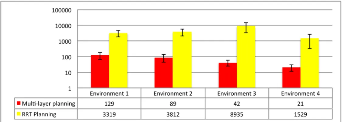
on this cluttered place. The number of random configura-tion used to find such paths is given in Fig.10. Depending on the crossed places and the paths defined by the RRT algorithm the number of random configuration needed is between 21 (Environment 4) and 129 (Environment 1). When using the RRT algorithm only, defining similar path needs from 1529 (Environment 4) to 8939 (Environment 3) random configurations.
5.1.3 Path re-planning
Figure 11 illustrates the topological re-planning includ-ing real-time prediction of user’s intent. In Fig. 11.a, in the first step, the user seems to prefer the narrow passage. Predicting it, the topological path is recomputed taking into account this intent. In Fig. 11.b, the user doesn’t fol-low the guidance along the geometrical path in the third topological step. Thus, the topological planner computes
a.Environment 1. b.Environment 2.
c.Environment 3. d.Environment 4.
Figure 9: Planning results
a new topological path. The path re-planning including fine planning process is performed enough fast to allow real-time interaction.
5.2 Shape as semantic information
5.2.1 Simulation scene
The simulation scene (Fig. 12) is made of a cubic workspace divided in three large places by two walls (Fig. 12.a). The wall in the foreground is an obstacle with
a.Re-planning in step 1. b.Re-planning in step 3.
Figure 11: Topological re-planning in environment 1 9
Environment 1 Environment 2 Environment 3 Environment 4 Mul2-‐layer planning 129 89 42 21 RRT Planning 3319 3812 8935 1529 1 10 100 1000 10000 100000
Figure 10: Average and standard deviation of number of random configurations used for path planning in the design application
a.Scene top view. b.Pierced wall.
Figure 12: Shape application environment four holes (Fig. 12.b). Each hole has a characteristic shape (square, triangular, round and pentagonal). The wall in the background is an obstacle leaving a passage on each side (a large one on the bottom and a narrow one on the top in Fig. 12.a). A moving obstacle clutters the place between these two walls.
The topological places of this environment are: the three large places, the two passages around the back-ground wall (Fig. 12.a), and the holes through the fore-ground wall, each hole corresponds to a place (Fig. 12.b). The semantic attributes attached to the places are: ”low complexity” for the three large places; ”high complex-ity” for the large passage around the background wall, and ”very high” for the narrow one. The additional ”clut-tered” semantic attribute is assigned to the places con-taining moving objects. Attributes are also set to the
Object\ Hole Circle Square Triangle Pentagon
Circle X X X
Square X X X
Triangle X X X
Pentagon X
Star X
Table 3: Object/hole compatibility
wall holes to describe their shape (”square”, ”triangular”, ”round” and ”pentagonal”). These shape attributes allow the automatic path planner finding an accurate topological path being guided according to the semantic information. However, to provide the VR user with topological path alternatives, shaped objects can cross the wall through differently shaped holes. The corresponding object/hole compatibility is given in Table 3.
The planning query here consists in passing the two walls to move one of the shaped object (colored) from one side of the cube to the other.
5.2.2 Path planning
Figure 13 shows the path (green rays) computed for the triangular object with our proposed architecture. What-ever the shape of the object (except the star object) is, the path planned crosses the first wall through the hole with the same shape. For the star object, as there is no hole with the same shape, the Topological path crosses the triangu-10
Figure 13: Planning results for triangular object lar hole and thus provide an inaccurate path that doesn’t allow to define non colliding path. Thus, to handle this query, the VR user have to move toward the pentagon hole to start a re-planning guided toward this shaped hole.
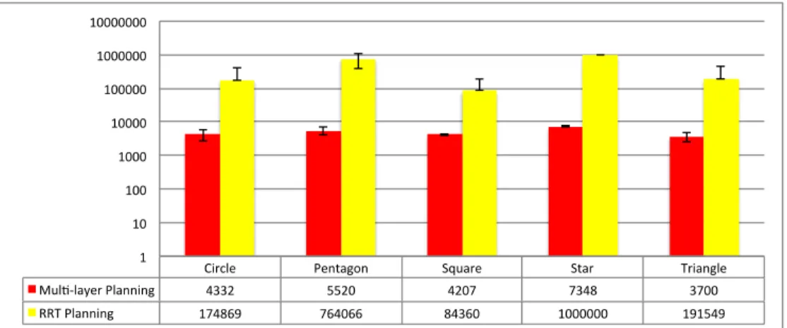
The number of configuration randomly defined to find a path for each objects is given in Fig.14. To get such re-sults, for the multi-layer planning, the non collision con-straint have been relaxed in the topological milestones (explaining that the automatic path planner find a path with colliding milestones in the triangular hole for the star object). For the RRT planning, the number of ran-dom configuration used have been limited to one million. Thus, for the RRT planning the nearer to one million the average number of random configurations is, the higher the failing rate is.
5.2.3 Path re-planning
Figure 15 illustrates the path re-planning in the case of the triangular object manipulation. Here, the user did not follow the haptic guidance along the geometrical path. In the first place, he moved toward the pentagonal hole starting thus the re-planning process. The resulting path goes through the pentagonal hole (Fig.15.a). In the mid-dle place between the two walls, he moved toward the
a.From first place. b.From middle place.
Figure 15: Interactive path re-planning
narrow passage, then the re-planned path goes that way (Fig.15.b). Thus, in both cases, a new multi-layer path planning is performed to take into account the operator’s intents. Once the new Topological path defined the guid-ance is updated to assist the operator along is preferred path.
6 Conclusion
This paper presents a novel multi-layer architecture for interactive path planning in VR simulations. This archi-tecture is based on a multi-layer environment model and a multi-layer planner. Each layer deals with specific infor-mation (semantic, topological and geometric). The con-tribution of such an architecture is two-fold :
• First, it provides the user with real-time manipula-tion guidance by involving the semantic and topo-logical information in the path planning process. The path planning process is accelerated by splitting the path in steps and then by adapting the geometric planning strategy to the local complexity of each step.
• Second, it integrates efficiently a human in the loop: path re-planning is computed based on real-time user’s intent prediction and motion control is shared by the user and the planner.
The interest of such a planner architecture had been demonstrated here with semantic information of the en-vironment based on ”complexity”, ”shape” and ”clutter-ing”. This information allowed this novel architecture to 11
Circle Pentagon Square Star Triangle Mul3-‐layer Planning 4332 5520 4207 7348 3700 RRT Planning 174869 764066 84360 1000000 191549 1 10 100 1000 10000 100000 1000000 10000000
Figure 14: Average and standard deviation of number of random configurations used for path planning in the shapes application
deal efficiently with an abstract example using only sim-ple geometrical path planning techniques.
However, real manipulation task for industrial pro-cesses involves more complex semantic information (functional surface, multi-physics interactions, surfaces or material properties). Future work will be done to further define both the meaningful semantic information needed for such tasks and the corresponding planning strategies. For instance, in assembly tasks, sliding motions are com-monly used. We are planning to develop interactive geo-metric path planning methods with contact. We also plan to enrich the topological and semantic layer of our envi-ronment model in order to use our global architecture to plan paths with or without contact according to the func-tional context of the assembly tasks (or subtasks) to be performed. The proposed architecture meets the require-ments for such semantic information.
Moreover, with an accurate semantic description, such a planner structure seems also well suited for off-line path planning allowing to rapidly find hard passages using the topological planning and to rapidly adapt the geometric planning strategy according to the local planning context.
References
[1] Aarno, D., Ekvall, S., Kragic, D.: Adaptive virtual fixtures for machine-assisted teleoperation tasks. In:
International Conference on Robotics and Automa-tion, pp. 1139–1144. IEEE (2005)
[2] Abbink, D.A., Mulder, M.: Neuromuscular analysis as a guideline in designing shared control. Advances
in haptics109, 499–516 (2010)
[3] Ahmadi-Pajouh, M.A., Towhidkhah, F.,
Gharibzadeh, S., Mashhadimalek, M.: Path
planning in the hippocampo-prefrontal cortex path-way: An adaptive model based receding horizon
planner. Medical hypotheses 68(6), 1411–1415
(2007)
[4] Anderson, S.J., Peters, S.C., Iagnemma, K., Over-holt, J.: Semi-autonomous stability control and haz-ard avoidance for manned and unmanned ground ve-hicles. Tech. rep., DTIC Document (2010)
[5] Bordegoni, M., Cugini, U., Belluco, P., Aliverti, M.: Evaluation of a haptic-based interaction system for virtual manual assembly. In: VMR, Conf´erence on Virtual and Mixed Reality, pp. 303–312. Springer (July 2009, San Diego (USA))
[6] CGAL: CGAL, Computational Geometry Algo-rithms Library (2014). http://www.cgal.org
[7] Choset, H., Lynch, K.M., Hutchinson, S., Kantor, G., Burgard, W., Kavraki, L.E., Thrun, S.: Princi-12