Open Archive TOULOUSE Archive Ouverte (OATAO)
OATAO is an open access repository that collects the work of Toulouse researchers and
makes it freely available over the web where possible.
This is an author-deposited version published in :
http://oatao.univ-toulouse.fr/
Eprints ID : 16758
To link to this article : DOI:10.1038/NENERGY.2016.70
URL :
http://dx.doi.org/10.1038/NENERGY.2016.70
To cite this version :
Salanne, Mathieu and Rotenberg, Benjamin
and Naoi, Katsuhiko and Kaneko, Katsumi and Taberna,
Pierre-Louis and Grey, Clare P. and Dunn, Bruce and Simon, Patrice
Efficient storage mechanisms for building better supercapacitors.
(2016) Nature Energy, vol. 1. pp. 1-10. ISSN 2058-7546
Any correspondence concerning this service should be sent to the repository
administrator:
[email protected]
T
he urgent need for efficient energy storage devices has resulted in a widespread and concerted research effort into electro-chemical capacitors, also called supercapacitors, in the past ten years. These devices consist of two high-conductivity electrodes separated by an electrolyte containing mobile ionic species. As in conventional capacitors, charge is stored at the surface of the elec-trodes through an excess of electrons on one side of the device and electron holes on the other side, on application of a voltage between the electrodes1. Unlike conventional capacitors, however, the chargeon the electrodes is then balanced by the adsorption of cations and anions, respectively, at their surface. The excellent performance of supercapacitors is due to the highly reversible ion adsorption mech-anism. In contrast to batteries, charging is not limited by diffusion of ions in the bulk of the electrodes, and hence higher power den-sities can be achieved. Supercapacitors can therefore complement and sometimes even replace batteries when high power delivery or uptake is needed2.
Two distinct families of supercapacitors can be considered. The principal one, electrochemical double-layer capacitors (EDLCs), uses porous carbon electrodes with high accessible surface area. This acts as an ‘electric sponge’, which adsorbs the ions from the electrolytes on charging and releases them at discharge. After years of incremental developments, the discovery of a different charg-ing mechanism in nanoporous carbons (with pore size smaller than 1 nm) has spurred further research into EDLCs3. As a
con-sequence, recent work has not only been directed towards new materials and architectures, but is also aimed at understanding the physical mechanisms underlying the charge storage in such materials. The development of in situ experiments, in particu-lar spectroscopy and diffraction, as well as advanced simulation techniques for the realistic description of complex interfacial
Efficient storage mechanisms for building
better supercapacitors
M. Salanne
1,2,3, B. Rotenberg
1,2, K. Naoi
4, K. Kaneko
5, P.-L. Taberna
2,6, C. P. Grey
7, B. Dunn
8and P. Simon
2,4,6*
Supercapacitors are electrochemical energy storage devices that operate on the simple mechanism of adsorption of ions from an electrolyte on a high-surface-area electrode. Over the past decade, the performance of supercapacitors has greatly improved, as electrode materials have been tuned at the nanoscale and electrolytes have gained an active role, enabling more efficient storage mechanisms. In porous carbon materials with subnanometre pores, the desolvation of the ions leads to sur-prisingly high capacitances. Oxide materials store charge by surface redox reactions, leading to the pseudocapacitive effect. Understanding the physical mechanisms underlying charge storage in these materials is important for further development of supercapacitors. Here we review recent progress, from both in situ experiments and advanced simulation techniques, in under-standing the charge storage mechanism in carbon- and oxide-based supercapacitors. We also discuss the challenges that still need to be addressed for building better supercapacitors.
processes, has radically modified our understanding of nanoporous carbon-based supercapacitors.
The second family of supercapacitors, known as pseudo-capacitors, is based on redox reactions that occur largely (but not exclusively) on oxide-based material surfaces4. Fundamental
stud-ies on pseudocapacitors remain scarce, because of the difficulty of characterizing the oxide surfaces and determining the details of the charge transfer mechanism. But the recent development of nanostructured oxides and of hybrid carbon/oxide electrodes is progressively changing the way we think about pseudocapacitive charge storage.
Despite the recent progress in both the performance and funda-mental understanding of the mechanisms involved in super capacitors, this body of work has not been placed in the broader context of capac-itive storage. Existing reviews in the literature either focus on the properties of the materials5–7 or on the electrolytes8,9. Here we review
both chemical and physical aspects of the capacitive storage mecha-nism in carbon- and oxide-based supercapacitors. We discuss the lat-est advances, which have implications not only for supercapacitors but also for other applications in which voltage-driven ion adsorption in nanoporous structures plays a key role.
Electrochemical double-layer capacitors
Charge storage in supercapacitor electrodes makes use of the electrostatic attraction between the ions of an electrolyte and the charges present at the electrode surface, which allows the formation of oppositely charged layers at the electrolyte/electrode interface. Supercapacitors use mainly porous carbon as electrode materials, thus benefiting from the high surface area available for ion adsorp-tion. The charge separation occurring upon polarization at the elec-trode/electrolyte interface can be described in a crude approach
1Sorbonne Universités, UPMC Univ. Paris 06, CNRS, Laboratoire PHENIX, F-75005 Paris, France. 2Réseau sur le Stockage Electrochimique de l’Energie
(RS2E), FR CNRS 3459, 80039 Amiens Cedex, France. 3Maison de la Simulation, USR 3441, CEA, CNRS, INRIA, Université Paris-Sud, Université de
Versailles, F-91191 Gif-sur-Yvette, France. 4Institute of Global Innovation Research, Tokyo University of Agriculture and Technology, 2-24-16 Naka-cho,
Koganei, Tokyo 184-8558, Japan. 5Research Center for Energy and Environmental Science, Shinshu University, 4-17-1 Wakasato, Nagano 380-8553, Japan. 6CIRIMAT, Université de Toulouse, CNRS, INPT, UPS, 118 route de Narbonne, 31062 Toulouse Cedex 9, France. 7Department of Chemistry, University
of Cambridge, Lensfield Road, Cambridge CB2 1EW, UK. 8Department of Materials Science and Engineering, University of California, Los Angeles,
using the double-layer capacitance model proposed by Helmholtz in 1853 (ref. 10):
C = εrε0A
d (1)
where εr is the electrolyte relative permittivity, ε0 is the vacuum
permittivity, d is the effective thickness of the double layer (charge separation distance) and A is the electrode surface area. Note, how-ever, that all these quantities (except for ε0) are ill-defined for the
interfaces at play in the present case of highly disordered materials. Until 2005, it was believed that the best strategy for increasing capacitance consisted in maximizing the electrochemical double-layer charging. The challenge at that time was therefore to develop new mesoporous carbons with the highest specific surface area. Then, following original work from the group of Aurbach11,12, the discovery
of a different, more efficient storage mechanism in nanopores (pore size less than 1 nm: that is to say, less than the size of solvated ions)3
led to a change of view: not only the surface area but also the pore size and the carbon nanostructure drive the electrochemical perfor-mance. The community thus had to reconsider the way that charge is stored at the carbon/electrolyte interface in ultra-small pores. Since then, much effort has been directed towards the basic understand-ing of charge storage mechanisms at the nano- and subnanoscales, considering both sides of the interface: the carbon structure and the electrolyte organization, including the (de)solvation of ions and their interactions under extreme confinement.
In this section, we show how the development and the use of new techniques, both theoretical and experimental, have been at the ori-gin of major advances in carbon-based supercapacitors. First, more realistic structural models for porous carbon structures have been developed by coupling modelling and characterization techniques such as small-angle X-ray scattering (SAXS) or neutron scattering (SANS), which greatly improve our understanding of their electro-chemical behaviour. In addition, the combination of advanced
electrochemical techniques such as electrochemical quartz crystal microbalance (EQCM), spectroscopies such as nuclear magnetic resonance (NMR) or infrared, and characterization techniques (SAXS), together with modelling, have led to the elucidation of electrolyte organization in carbon nanopores at null potential and under polarization, as well as the charge storage mechanism and the ion dynamics in the pores. These points are detailed below.
Structural models for nanoporous carbons. Nanoporous carbons
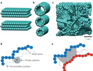
generally consist of defective nanoscale graphitic units, with pores ranging from micropores (pore size <2 nm) to mesopores (from 2 to 50 nm). Unlike slit pores or nanotubes (Fig. 1a,b), they do not display any three-dimensional (3D) long-range ordering (Fig. 1c). Because the electrochemical performance of carbons is driven by the porous carbon/electrolyte interface, accurate and reliable char-acterizations of the porous network are needed for designing better supercapacitors. Specific surface area and pore size distributions of porous material are generally obtained from gas adsorption tech-niques, using theoretical models. But such methods suffer from several limitations when applied to microporous carbons.
Choosing an appropriate molecular probe is essential, as pores inaccessible to gas molecules may be accessible to ions from the electro lyte, depending on thermodynamic conditions (Fig. 1d,e). This is specifically true when N2 adsorption at 77 K is used to measure the
carbon specific surface area. The quadrupole moment of the N2
mol-ecule limits the access of the gas to small micropores, and reduced flexibility of the porous carbon network structures at low tempera-tures does not necessarily reflect the ambient temperature properties. As a result, N2 sorption does not give accurate porosity values for
ultramicropores (<0.7 nm). Without a quadrupole moment and with a smaller diameter (0.335 nm compared with 0.363 nm), Ar atoms can access small micropores more easily than N2. Combined with a
higher experimental measurement temperature and a simpler theo-retical analysis, this makes Ar adsorption at 87 K more suited than N2 for the characterization of microporous carbons13. A
complemen-tary approach involves using the adsorption of supercritical gas or subcritical fluids (CO2) at ambient temperature, which improves the
adsorption kinetics.
The choice of the probe and of the experimental conditions is only part of the challenge, as the microscopic features must then be extracted from the experimental isotherm by means of an appro-priate model. The Brunauer–Emmett–Teller (BET) analysis14 is not
recommended for microporous carbons, as recently confirmed by the International Union of Pure and Applied Chemistry15, as it
over-estimates the surface of large micropores (>0.7 nm) by 10 to 40%, owing to enhanced bilayer gas adsorption on carbon pore walls. In addition, the BET surface area of ultramicropores (<0.7 nm) is underestimated owing to incomplete monolayer formation. Reliable porosity values for larger micropores (>0.7 nm) can be experimentally obtained by the subtracting pore effect method (SPE) using a high-resolution αs-plot, at low relative pressure (from
P/P0 = 10–6)16,17. Moving from measurements of surface area to
meas-urements of pore size distribution, quenched solid density func-tional theory analysis can provide reasonable structural information from high-resolution adsorption isotherms18.
All of this illustrates the difficulty of measuring the surface area of nanoporous carbons. Furthermore, the very concept of ‘surface’ by itself could be questionable, as it depends on the approach (that is, the probe) used to measure it19. Therefore, methods based on
molecular probes should be complemented by alternative direct characterization techniques such as SAXS and NMR spectroscopy, which can assess the whole pores of nanoporous carbons that are accessible to the electrolyte ions, and thus are directly relevant to the electrochemical measurement. Despite such limitations, it remains reasonable to discuss the dependence of the capacitance per unit surface area on pore size based on Ar adsorption data, to provide a
1 nm
a b c
Wall atom
dmin Probe sphere Accessible surface
d e
Figure 1 | Examples of nanoporous carbon structures. a–c, Although
ordered structures such as slit pores (a) and nanotubes (b) exist, most supercapacitors use disordered nanoporous carbons (c). The definition of the accessible surface depends on the choice of the probe and on the nature of the porosity. d,e, In mesopores, the whole surface is accessible (d), whereas in micropores (e) some regions of the pores are inaccessible to probe molecules or ions. In e, blue and red spheres represent wall atoms at opposite sides of a micropore, and the blue and red dashed lines represent the closest surfaces to these that are accessible by the probe sphere. Where the dashed lines cross, the pore wall is inaccessible, as indicated by the grey-shaded area in e.
method for comparison between samples and preparation method. Nevertheless, gravimetric capacitance (farad per gram of carbon) or volumetric capacitance (farad per volume of electrode) is preferred, as these are based on experimental, measured values, free from any theoretical model or structural considerations.
Revealing the ‘real’ structure of nanoporous carbons is much more complex, because it is not currently possible to resolve such structures by resorting only to experimental approaches. To that end, combinations of experimental and modelling techniques have been proposed. One may, for example, use synchrotron X-ray dif-fraction and SAXS experiments to obtain short- and long-range structural information on the porous carbon network. But scattering techniques usually give access to 1D structural information, and the corresponding data must be transformed into 3D structures by the use of hybrid reverse Monte Carlo simulation20,21. Combinations of
NMR, pair distribution function analysis of X-ray data, and Raman spectroscopy with lattice simulations have recently been used to evaluate the size of the graphene domains in the porous carbons22.
Alternatively, quenched molecular dynamics has been used success-fully to describe the structure of nanoporous carbons without resorting to experimental structural data23,24.
We finally note that most studies so far have focused on the structure of the nanoporous carbon only, whereas the ability to pre-dict the key features of the structure needed to optimize the charge storage also requires a deeper understanding of the structures and dynamics of the confined electrolyte.
Wetting of the pores at null potential. Until recently, the charging
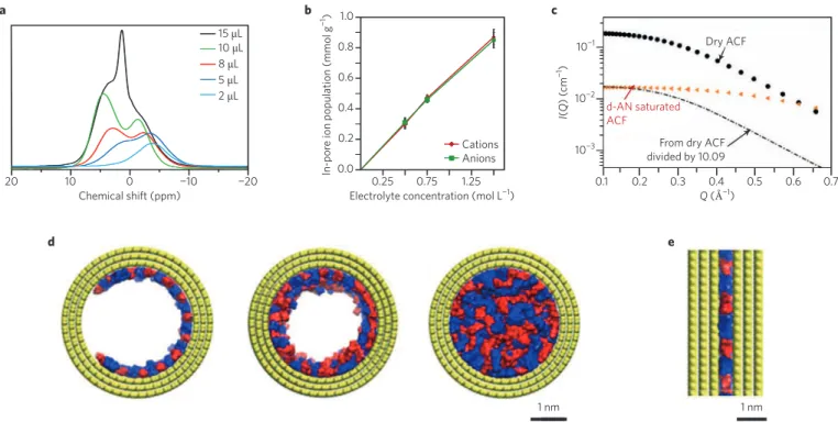
of supercapacitors was assumed to arise from a simple mechanism of the applied potential driving the ions into the porous carbon net-work. The first in situ NMR studies have shown that this is not the case: even at low electrolyte loadings, NMR signals are observed that are shifted towards lower frequencies, as shown in Fig. 2a (refs 25–29), owing to the aromatic ring-current effects of graphitic domains and magnetic susceptibility of the carbon. The results
indicate that ions (along with the solvent) are adsorbed within the pores. The starting situation at 0 V is therefore better characterized by the interpenetration of the two heterogeneous structures — the solid carbon material and the electrolyte. Molecular dynamics sim-ulations further confirmed this picture, showing that an ionic liquid in contact with a nanoporous carbon electrode spontaneously fills the highly confined nanopores, even without any applied field30–32.
NMR spectroscopy is quantitative and thus provides the con-centrations of ions adsorbed inside the electrode. The latter follow a linear trend with respect to their counterparts inside the bulk electro lyte26 (Fig. 2b), thereby confirming the affinity of the ions
for the carbon. As the ions diffuse between pores during the signal acquisition, however, they experience various environments, result-ing in relatively broad NMR spectra33. It is therefore not
straight-forward to determine the population of the various adsorption sites (for example mesopores versus micropores) using this technique. Another approach is SANS or X-rays. In an empty porous carbon, the signal at small wave vectors originates from the contrast between the carbon atoms and the pore voids. For example, nanopores with a characteristic length scale d of 1–2 nm display a signature around 2π/d ≈ 3–6 nm–1. When the pores are filled with the electrolyte, this
contrast vanishes and the signal decreases. An example of the appli-cation of in situ SANS to a typical activated carbon, either empty or loaded with an organic electrolyte, is shown in Fig. 2c (ref. 27). The decrease in the scattering intensity depends on the wave vector, revealing an incomplete wetting of the smallest pores.
In contrast, Bañuelos et al. combined SANS and molecular dynamics simulations to investigate the adsorption of a room- temperature ionic liquid (RTIL) inside a hierarchical porous carbon at various loadings28 and concluded that the RTIL covers the pore
surfaces uniformly, rather than leaving some pore surfaces unsatu-rated. Their pictures of the wetting of mesopores and micropores are shown in Fig. 2d and e, respectively. Different results were observed in the case of aqueous electrolytes34, suggesting that the surface
chemistry of the carbon and the nature of the electrolyte strongly
20 10 0 −10 −20 15 μL 10 μL 8 μL 5 μL 2 μL Chemical shift (ppm) a 0.25 0.2 0.4 0.6 0.8 0.75 1.25 Cations Anions 1.0 0.0
Electrolyte concentration (mol L−1)
In-por
e ion population (mmol g
−1) b 0.1 0.2 0.3 0.4 0.5 0.6 0.7 Q (Å−1) 10−3 10−2 10−1 I( Q ) ( cm −1) Dry ACF
From dry ACF divided by 10.09 d-AN saturated ACF c 1 nm 1 nm d e
Figure 2 | Characterization of pore wetting at null potential. a, NMR spectra with different electrolyte loadings inside nanoporous carbon. ppm, parts per
million. b, Number of ions adsorbed inside the pores with respect to the electrolyte concentration. c, Neutron scattering experiments on dry or electrolyte-saturated activated carbon electrodes. Q, scattering vector; I, intensity; ACF, activated carbon fabric; AN, acetonitrile. d,e, Adsorption of ionic liquids inside a mesopore and a micropore from molecular dynamics simulations (yellow, pore wall atoms; red, cations; blue, anions). Figure reproduced from: a, ref. 25, American Chemical Society; b, ref. 26, NPG; c, ref. 27, American Chemical Society; d,e, ref. 28, American Chemical Society.
affect the wetting properties. Recently, Kondrat and Kornyshev have proposed to use ‘ionophobic’ pores for designing a new generation of supercapacitors35. Their idea, which remains to be realized
exper-imentally, is built on the fact that such pores would be filled for high voltage only; this could potentially result in larger energy densities and rapid rates of charge and discharge.
Desolvation in nanopores. The discovery that ions could access
carbon pores smaller than their solvated ion size has revitalized research into ion confinement in carbon nanopores. From electro-chemical measurements, it was proposed that ions lose a part of their solvation shell to access these small nanopores (<1 nm). In addition, the capacitance was strongly enhanced when the carbon pore size was in the same range as the ion size3,36–38. Although such
observations were made using carbon with tailored pore sizes, the use of conventional electrochemical techniques failed to give quan-titative information on the extent of desolvation. The development of in situ techniques such as EQCM has led to important advances in addressing this issue. Figure 3a shows a schematic of an EQCM set-up; the change of the quartz resonance frequency reflects the change of weight of the active material during the polarization.
The use of EQCM to study ion adsorption in porous carbons was pioneered by Levi and Aurbach39–41. Figure 3b shows typical
changes of ion population as a function of the charge accumu-lated in a porous carbon electrode during polarization in aqueous electrolyte with varying alkali cations39. In this example, from the
associated mass change and comparison with the theoretical mass change expected for the adsorption of bare ions from Faraday’s law, it was shown that the adsorbed Li+, Na+, K+ and Cs+ ions are tightly
attached to 2.0, 0.8, 0.1 and 0.0 water molecules on average. The confinement of the ions is therefore accompanied by a substantial decrease in their solvation number (number of solvent molecules around the ion), thus confirming previous results42.
EQCM was also used in organic electrolytes in combination with carbons of 1-nm average pore diameter43. A solvation number
between three and four could be calculated for 1-ethyl-3-methyl-imidazolium cations confined in the 1-nm pores, much smaller than the eight molecules for cations in the bulk electrolyte. The joint use of NMR spectroscopy and EQCM allowed the effects from the cations and anions to be separated and the cation solvation number to be determined26. These results clearly indicate that the partial
des-olvation of the ions occurs when accessing small pores. The decrease in the ion solvation number could also be quantified directly in molecular dynamics simulations31. Importantly, these studies point
out a difference in the energy storage mechanism depending on the electrode polarity, as described below in more detail.
Quartz
Porous carbon and binder slurry
PTFE holder Electrochemical cell EQCM Potentiostats CE: Pt mesh RE: Ag WE: quartz a −0.8 −0.6 −0.4 −0.2 0.0 0.2 0.4 Q (mC cm−2) 0 5 10 15 20 25 ∆Г (nmol cm −2 ) Li+ Na+ K+ Cs+ b −0.003 −0.002 −0.001 0.0 0.001 0.002 0.003 Q (C) 0 2 4 6 8 ∆ m (μ g)
Cation absorption Ion swapping zone
Anion absorption
265 g mol−1
208 g mol−1
Measured mass change (EQCM) Theoretical mass change (neat ions) Linear fitting Four solvent molecules F O O F F F C S O O N F F S − C 7.9 Å 2.9 Å TFSI anion C H H H C C N N C C C H H + H H H H H 4.3 Å 7.6 Å EMI cation 111 g mol−1 c
Figure 3 | Desolvation of the ions in electrified nanopores. a, EQCM set-up. RE, reference electrode; CE, counter electrode; WE, working electrode. b, Variation of the adsorption of ions with respect to the accumulated charge per unit area in aqueous electrolytes with various alkali cations. Dashed
lines represent the theoretical mass change (Faraday’s law for neat ions). c, Variation of the mass with respect to the accumulated charge in an organic electrolyte. EMI, 1-ethyl-3-methylimidazolium; TFSI, bis(trifluoromethylsulfonyl)imide anion. Figure reproduced from: b, ref. 39, American Chemical Society; c, ref. 43, American Chemical Society.
Charge storage mechanism. Although the basic principle under-lying charge storage in EDLCs, namely the adsorption of ions at the surface of the electrode, is well established, the corresponding microscopic mechanisms have remained elusive until recently. The Gouy–Chapman–Stern theory, which has been the cornerstone of theoretical electrochemistry for over a century, predicts that near an extended surface, the electrode charge is balanced by the polariza-tion of the electrolyte. The decay of the ionic charge distribupolariza-tion and of the electrostatic potential occurs over the ‘Debye length’, typically in the 1–10 nm range, which depends on the electrolyte concen-tration and solvent permittivity. But this picture is of limited help in understanding the interfacial structure and thermo dynamics in the case of supercapacitors, owing to the strong ionic correlations at high electrolyte concentration or in pure ionic liquids44 and to
the marked effects of confinement30–32,45. The behaviour of such
electrolytes near metallic walls, noticed as early as 195246, has called
for a paradigm change44,47, and recent advances in simulation
tech-niques48 have shown that it is also important to consider the
electro-lyte structure at the electrode surface49,50. Recent claims based on
surface force apparatus experiments have also revived the debate on the differences between electrochemical interfaces involving pure ionic liquids and those of solvent-based electrolytes51–54.
In the case of planar graphitic electrodes, the Gouy–Chapman– Stern theory predicts an increase in the capacitance with the applied potential. This theory does not, however, capture two important features, namely the ionic correlations and the finite surface area accessible to the ions. This explains why it fails at reproducing, even qualitatively, experimental results in highly concentrated electro-lytes47. Mean-field theories accounting for these effects and
molecu-lar simulations44,55 show that the differential capacitances may display
various shapes (the ‘camel’ or ‘bell’ shapes) depending on the nature of the electrolyte. But these capacitance values remain too small to be exploited efficiently in supercapacitor devices.
An important consideration for extreme confinement, when pore sizes are comparable to the diameter of the ions, is that the electronic charge inside the electrode is compensated by an imbalance in the
number of co- and counter-ions inside the pores. In such a ‘super-ionic state’, the local breakdown of electro-neutrality in the inter stitial fluid is compensated by the creation of a corresponding charge on the metallic surface that efficiently screens the interactions between like-charged ions56,57. Several processes may lead to the overall excess
of counter-ions inside an electrode: adsorption of counter-ions, swapping of co-ions for counter-ions, or desorption of co-ions58.
For a given combination of electrodes and electrolyte (nature of the ions, presence and choice of a solvent), one or several of these mechanisms are observed as a function of voltage. NMR, molecular dynamics, infrared spectroscopy, SAXS and EQCM suggest that ion swapping is the most common process at low voltage, but for large ion sizes and/or at high voltage, adsorption of the sole counter-ions is also observed, as illustrated in Fig. 3c. Desorption of co-ions seems to be less frequent. Recent in situ NMR measurements on a solvent-based electrolyte have shown that the charge storage mechanism can differ depending on the electrode polarization; ion swapping was observed for positive polarization, whereas counter-ion adsorption dominated for negative polarization. This suggests that multiple fac-tors may influence how excess ionic charge is achieved, including relative sizes and mobilities of co/counter-ions, kinetic phenomena and ion rearrangement over multiple cycles. Coupling NMR with EQCM also showed that both counter-ion adsorption and ion swap-ping are accompanied by the entrance or departure of solvent mol-ecules26. In pure ionic liquids, molecular simulations suggest that
the exchange occurs almost without changing the volume occupied by the liquid inside the electrode30, but this conclusion should be
strengthened by considering further combinations of cations and anions, and requires experimental confirmation.
The fundamental understanding of the microscopic charging mechanisms achieved in the past five years provides a strong basis for the design of better supercapacitors, by suggesting new strategies for the optimization of charge storage through appropriate combi-nations of electrode structures, ions and solvent. The widespread use of experimental and simulation tools developed to establish these mechanisms will be the key to the success of this endeavour.
800 1,600 2,400 3,200 4,000 4,800 −0.4 −0.2 0.0 0.2 0.4 Normaliz ed absorbanc e ( A (t )− A0V )/ A0V Time (s) −1.5 −1.0 −0.5 0.0 0.5 1.0 1.5 V oltag e (V)
Anion Cation Voltage
a 1 2 3 4 5 6 78 Q (nm−1) −1 0 1 1,200 800 400 0 U (V) T ime ( s) 1.04 1.00 0.96 R elativ e int ensit y b −0.04 0.00 0.04 0.08 Char ge ( e) t = 0.2 ns t = 1.0 ns t = 2.0 ns t = 2.4 ns c
Figure 4 | Characterization of the charging dynamics of supercapacitors. a, Temporal variation of the normalized infrared absorbance for various
charge–discharge cycles (ionic liquid electrolyte). b, Temporal variation of the SAXS intensity (right panel) for various charge–discharge cycles (aqueous CsCl electrolyte). Q, scattering vector. The evolution of the applied potential U with time is shown in the left panel. c, Time evolution of the local charge on the carbon atoms on charging in a molecular dynamics simulation (turquoise sticks, C–C bonds; red spheres, cations; green spheres, anions). Figure reproduced from: a, ref. 60, American Chemical Society; b, ref. 61, RSC; c, ref. 65, American Chemical Society.
Dynamics of charging and discharging. The key feature of super-capacitors, for example with respect to batteries, is their very high power density: they are able to charge or discharge within a few sec-onds. The increase in capacitance should therefore not be achieved at the price of a decrease in power. Conventional theories predict that liquids suffer from noticeable slowdown of their dynamics when they are strongly confined, disqualifying in principle the use of microporous carbons for supercapacitors. Fortunately, such effects have not been observed in experiments performed on carbide-derived carbons (CDCs), for which a maximal characteristic dis-charge time of 20 seconds was obtained for the smallest average pore size3. This trend is further confirmed by electrochemical impedance
spectroscopy. This technique offers the possibility of measuring in-pore resistivities in the low-frequency region. These resistivities are usually of the order of 50 to 200 ohm cm for electrolytes made of organic ions dissolved in acetonitrile at room temperature — only slightly higher than for the same liquids under bulk conditions59.
The fast charging of supercapacitors impedes the application of the usual in situ techniques to monitor their dynamical behaviour. In many cases, the time needed to record a spectrum or a diffractogram is longer than their charging time. However, techniques such as infra-red spectroscopy or SAXS have been used to study charge/discharge cycles of supercapacitors at a low scan rate of 5 mV s–1. Figure 4a and
b shows the relative evolution of the signal with time and potential, in two different experiments. In one case, a supercapacitor made of
1-ethyl-3-methylimidazolium bis(trifluoromethylsulfonyl)imide ionic liquid and a CDC electrode is studied by infrared spectroscopy60. In
the second case, the adsorption of an aqueous CsCl electrolyte inside a microporous activated carbon is studied by SAXS61. In both cases, the
response of the liquid closely follows the applied potential, with a lag of only a few seconds. These observations are consistent with a timescale of seconds for charging microporous supercapacitors. NMR and mag-netic resonance imaging (MRI) studies have highlighted the role of the cell design in the timescale of ionic response during charging. Using a non-optimal ‘shifted’ cell design to allow electrodes to be studied independently, in situ NMR experiments revealed a lag between the applied potential and charge build up on the electrode even at a low scan rate, which is due to ohmic drop25. This issue was subsequently
addressed through the use of MRI which allows spatial resolution of the two electrodes in a conventional cell design62.
The microscopic origin of the observed fast charging has been studied using molecular simulations. In particular, molecular dynamics provides the trajectories of the molecules and is perfectly suited for extracting transport properties such as diffusion coeffi-cients. Recent work has shown that the diffusion coefficients of the ions are generally one to two orders of magnitude smaller in the elec-trodes than in the bulk liquid59,63, but strong variations are observed
with the filling of the electrode in the case of ionic liquids63,64. Indeed,
Kondrat et al. have shown that in slit pores, the ions can even dif-fuse faster than in the bulk at intermediate voltages63. In CDCs, this
effect is not observed but the good connectivity between the pores was shown to be an important characteristic, allowing the larger pores to play the role of electrolyte reservoirs as shown in Fig. 4c (ref. 65). Injecting molecular dynamics results into an equivalent circuit model then leads to estimated charging times of 1 to 10 s for CDC electrodes65, further demonstrating the good predictive power
of these simulations.
Oxide-based supercapacitors
In the 1970s, Conway and others recognized that certain materials undergo redox reactions at or near their surface and yet their electro-chemical properties are similar to those of supercapacitors, which store energy at the electrical double layer formed at the electrode/ electrolyte interface1. These pseudocapacitive materials lead to much
higher levels of charge storage than EDLCs, owing to the redox reac-tions4. For this reason, over the past several years there has been
grow-ing interest in pseudocapacitors because of the prospect of achievgrow-ing the high energy density of traditional battery electrode materials combined with the long cycle life and power density of EDLCs66.
The mechanism of pseudocapacitance. The most widely
investi-gated pseudocapacitors are RuO2 and MnO2. As the field has
devel-oped, certain metrics have emerged that provide a more rigorous identification of pseudocapacitance. In particular, materials exhib-iting high energy density at high discharge/charge rates display electro chemical signatures that are representative of pseudocapaci-tive behaviour. An especially good model system in which to charac-terize pseudocapacitance is Nb2O5, as 70% of its theoretical capacity
for lithium can be stored in only 1 minute (125 mAh g–1 for 1-minute
discharge)67. Moreover, charge storage by means of redox reactions
takes place in the bulk of the material and not only at the surface as is commonly thought68. The charge storage mechanism involved here,
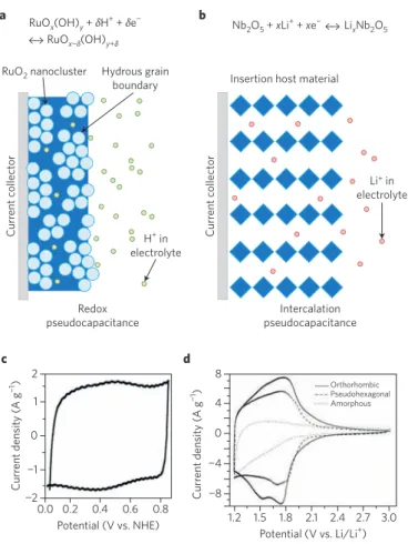
intercalation pseudocapacitance, is not controlled by semi-infinite diffusion and instead exhibits the fast kinetic response observed in double-layer capacitors (leading to high power) despite the fact that charge storage arises from redox reactions. A comparison between intercalation pseudocapacitance and the redox pseudocapacitance69
that characterizes RuO2 is shown in Fig. 5. Some of the key
electro-chemical responses associated with pseudocapacitance include: (i) a linear dependence of the potential on the state of charge; (ii) a charge-storage capacity mostly independent of rate; and (iii) redox
C urr ent c ollect or C urr ent c ollect or H+ in electrolyte Hydrous grain boundary RuO2 nanocluster Redox pseudocapacitance RuOx(OH)y + δH+ + δe−
RuOx−δ(OH)y+δ
Li+ in
electrolyte Insertion host material
Nb2O5 + xLi+ + xe− Li xNb2O5 a b Intercalation pseudocapacitance 0.0 0.2 0.4 0.6 0.8 Potential (V vs. NHE) −2 −1 0 1 2 C urr ent densit y ( A g −1) 1.2 1.5 1.8 2.1 2.4 2.7 3.0 Potential (V vs. Li/Li+) −8 −4 0 4 8 Pseudohexagonal Orthorhombic Amorphous C urr ent densit y ( A g −1) c d
Figure 5 | Different types of pseudocapacitive behaviour.
a, Redox pseudocapacitance in RuO2 occurs in the near-surface region.
b, Intercalation pseudocapacitance in Nb2O5 (T-phase) is a bulk effect from
Li+ insertion. c, Cyclic voltammetry experiments show the RuO 2 to have
the traditional capacitor ‘box’. d, Cyclic voltammetry experiments show that the orthorhombic Nb2O5 (T-phase) exhibits redox peaks with little
voltage offset. Figure reproduced from: a,b, ref. 66, RSC; c, ref. 69, American Chemical Society; d, ref. 67, Wiley.
peaks with small voltage offsets70. Materials that do not show such
features should not be considered pseudocapacitive. The recent paper by Brousse et al. points out the limitations in describing materials such as Ni(OH)2 or cobalt oxides as being pseudocapacitive71.
Pseudo-intercalation reactions. Another important
considera-tion for pseudocapacitive materials is that the structure does not undergo a phase transformation on intercalation. In this regard, when MoO2 is prepared as a nanoscale material, its characteristic
monoclinic-to-orthorhombic phase transition, which occurs on lithiation, is suppressed and the material shows the pseudocapacitive responses mentioned above. The gravimetric capacity for nanoscale MoO2 for 2-minute discharge rate is nearly 200 mAh g–1, far
exceed-ing the energy density of any other material at this rate72. Additional
studies show that pseudocapacitive behaviour is preserved even in 40-μm-thick Nb2O5 films. Such films have been incorporated in
a hybrid cell comprising a Nb2O5 negative electrode and activated
carbon as the positive electrode68. Although this device showed very
good performance, it was limited by the energy density of the carbon electrode, which stores energy by means of the electrical double layer.
One of the more popular approaches to developing pseudo-capacitor materials involves the synthesis of nanoscale materials73.
Growing evidence indicates that electrochemical characteristics tend to become more capacitor-like when the crystallite is smaller than 20 nm. For example, the potential dependence on state of charge (see (i) above) can become linear owing to a larger num-ber of surface sites for charge storage or the suppression of a phase transition. Kinetics are also influenced by the small crystallite size, as the decrease in diffusion distance leads to higher power density. In addition, the use of sweep voltammetry to separate diffusion- controlled kinetics from capacitive processes shows nanoscale materials to be more capacitor-like66. Thus far, the charge storage
mechanisms for only a few 2D materials prepared in the form of nanosheets have been characterized. In the case of TiO2, a
surface-controlled response reported for this material is expected, as nearly the entire surface of the sample is exposed to electrolyte74.
To account for the role of nanostructuring, Simon, Dunn and colleagues recently proposed that pseudocapacitance can be intrin-sic or extrinintrin-sic to a material68. An intrinsic pseudocapacitor shows
the various electrochemical signatures of double-layer capaci-tors regardless of particle size or shape: MnO2 is a good example
of intrinsic behaviour71,75,76, although the structural behaviour
and charge storage of the material changes from one allotrope to another77, as shown by in situ synchrotron X-ray diffraction
analy-ses78. In contrast, the extrinsic term applies to materials that show
pseudocapacitor characteristics only as nanoparticles. With these materials, the diffusion distance is less than (Dt)1/2, where D is the
diffusion coefficient and t the time. These materials do not show pseudocapacitive behaviour in the bulk state. The extent to which nanostructuring produces pseudocapacitance is likely to cover a wide range of transition metal oxides, sulfides and nitrides, and is currently an active area of research. As shown with MoO2, the
extrinsic pseudocapacitor approach provides the exciting opportu-nity of creating materials that possess both the high energy density of battery materials and the high power density of capacitors. Hybrid supercapacitors
The desire to increase the energy density of EDLCs coupled with the growing interest in pseudocapacitor materials has led to the design of composite hybrid materials79,80. The development of these fast
charge/discharge materials is providing the basis for creating the next generation of hybrid supercapacitors.
The most advanced hybrid supercapacitors are based on the use of high-rate Li4Ti5O12 (LTO), another lithium-ion insertion material.
This material retains a lithium capacity in excess of 120 mAh g–1 at
a charge/discharge rate of 30C (full discharge in 2 min). Moreover,
in contrast to MnO2 and RuO2 which operate in aqueous electrolytes
within a limited potential window (about 1 V), LTO functions in high-voltage non-aqueous electrolytes. LTO cannot be defined as a pseudo-capacitive material, as it shows a voltage plateau and undergoes a phase change during lithiation. Because it exhibits zero strain and supports rapid Li+ ion transport during the (de)intercalation reaction, however,
LTO is suitable for use in high-rate electrodes in hybrid supercapaci-tors, devices that combine a faradaic battery electrode with a capacitive electrode. The first generation of commercial hybrid supercapacitors, called the Li-ion capacitor, was based on combining a negative graph-ite electrode of a Li-ion battery with a capacitive porous-carbon posi-tive electrode81. The use of ultrafast Li-ion intercalation materials such
as LTO could greatly increase the power capability of such devices, while preserving high energy density82.
In recent work, ultracentrifugation synthesis has been explored to further extend the performance of high-rate and pseudocapaci-tive materials such as RuO2 (ref. 83). The ultracentrifugation
pro-cess enables the preparation of nano-sized, dimension-controlled (1D to 2D) materials, directly bound on high-surface-area carbons such as carbon nanotubes (CNT) or disordered porous carbons84.
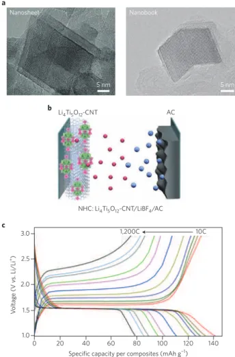
Dimension-controlled 2D-LTO is shown in Fig. 6a. High-resolution
5 nm Nanosheet a 5 nm Nanobook AC Li4Ti5O12-CNT NHC: Li4Ti5O12-CNT/LiBF4/AC b 0 20 40 60 80 100 120 140 Specific capacity per composites (mAh g−1)
1.0 1.5 2.0 2.5 3.0 V oltag e (V v s. Li/Li +) 10C 1,200C c
Figure 6 | Nanohybrid supercapacitor set-up and characterization. a, High-resolution transmission electron microscope images of
nanocrystalline Li4Ti5O12 prepared as ‘nanosheets’ and/or ‘nanobooks’
that are fabricated in composites with CNTs using ultracentrifugation (~75,000g). b, Nanohybrid capacitor (NHC) using an activated carbon (AC) and dimension-controlled Li4Ti5O12 nanocrystals composited
with single-walled CNTs. c, Discharge curves at various C-rates (from 10 to 1,200) after charging at a fixed rate of 10C. Figure reproduced from:
transmission electron microscopy images clearly demonstrate that 2D-LTO nanosheets nucleate from the CNT surface and are firmly attached to it. Fast Fourier transform analysis revealed the d-spacing of lattice fringes as 4.81 Å, corresponding to the (111) plane of the 3D spinel structure85. The surrounding interstitial carbon
influ-ences the growth direction, shape and size of the 2D-LTO crystals. One fascinating nanoscale morphology is that which occurs from two interconnected LTO nanosheets (a ‘nanobook’; Fig. 6a). These dimension-controlled LTO show ultrafast charge/discharge behav-iour when operated in excess of 300C (full discharge in 12 s) and as high as 1,200C (full discharge in 3 s), as shown in Fig. 6c.
Energy storage devices based on hybrid supercapacitors are being commercialized, and this underscores the importance of these new materials. A three- to fivefold increase in energy density compared with conventional carbon-based EDLCs has been achieved by com-bining a negative electrode made of ultracentrifugation-prepared LTO nanosheets with a porous-carbon positive electrode. Although the stability of the nanostructured electrode/electrolyte interfaces is still an important issue to be solved, this technology has the potential to become an alternative to EDLCs84.
Outlook
Supercapacitor electrodes, which used to be a black box, can now be probed at the molecular scale using a variety of experimental and simulation techniques. Our view on the structure of the inter-face has profoundly changed in the past ten years, as summarized in Fig. 7. The discovery of a new storage mechanism inside nano-porous carbons has enabled large improvements in the energy den-sity of commercial EDLC devices, which now reach specific energies beyond 6–7 Wh kg–1. These devices are now used in power
electron-ics, in cars (stop/start systems), and in public transport systems such as trams and buses. The next challenge will be to push this limit further (>10 Wh kg–1), thus establishing supercapacitors as ideal
candidates in other key applications.
If we consider only porous carbon-based supercapacitors, the pos-sibilities are virtually infinite. On the electrode side of the interface, it is possible to tune the carbon porosity, composition (by activation or using dopants) and microstructure86. The impact of carbon
dop-ing remains to be understood. For example, includdop-ing nitrogen in the structure enhances the performance thanks to an additional faradaic contribution, so far limited to aqueous electrolytes87. On the
electro-lyte side, numerous cations, anions and solvent molecules can be used. The development of high-throughput techniques, such as the ones already applied to battery materials and electrolytes88, will be a
big step forward in that direction89. But there is still a need for
sys-tematically defining the good descriptors that can be extracted from simulations in order to select a few promising systems among thou-sands of candidates. Clearly such descriptors can only be designed
from the knowledge gained from the combination of all the infor-mation extracted from in situ experiments and understanding at the molecular level. Once the relationships among the carbon morphol-ogy, the pore size distribution, the size of the ions and the capacitance of the systems are established, the key for enhanced energy densities will depend on surface functionalization90 and on improvement of
the operating potential by formulating better electrolytes91,92.
The potential for improvement is even larger for oxide-based pseudo capacitors. Although recent studies have shed some light on the main features of the various mechanisms involved (for example simple surface redox reactions versus pseudo-intercalation), their molecular aspects remain mostly unknown. There is, therefore, an explicit need to adapt the in situ experiments and simulations that have been success-fully applied to carbon-based supercapacitors for oxide materials. But there are challenges due to the difficulty in obtaining well-defined interfaces both structurally and chemically. Certain oxide supercapac-itors operate in aqueous solvents for which acid/base effects must be taken into account, whereas other oxide systems involve the develop-ment of nanostructured, nanocrystalline metal oxide particles oper-ating in non-aqueous electrolyte. Two-dimensional materials such as MoS2 and the compounds known as MXenes have recently been tested
for supercapacitor applications93,94. Here also, pseudocapacitive effects
are at play, but it is likely that the microscopic mechanisms derived for oxide materials will not be relevant for these materials. The use of in situ characterization techniques95,96 will be a decisive step towards
improving the energy density of these materials.
Fundamental understanding of ion adsorption and charge storage in supercapacitors is essential for applications and technologies. In the area of energy storage, adsorption processes in porous carbons are of central importance for several technologies. One noteworthy exam-ple is redox flow batteries97, both aqueous and non-aqueous, which
are rapidly progressing towards commercialization because of both centralized and distributed systems that store energy from renewable sources. Biofuel cells, both enzymatic and microbial, represent a well-established sustainable technology in which adsorption processes on porous carbon electrodes are critical for achieving the redox processes involved in energy conversion98. Other emerging energy
technolo-gies include flow capacitors99 and ‘blue energy’. The latter is based on
extracting the energy associated with the mixing of fresh river and salty seawater100 or on osmotic power harvesting under salinity
gra-dients101. In addition, applications of ion adsorption in carbon-based
systems extend beyond energy storage to areas such as biosensors102 as
well as gas-phase sensors for detection of toxic gases103, while the use
of carbon electrodes for desalination represents an increasingly attrac-tive technology for drought-stricken areas. As these examples show, the experimental and theoretical tools developed and the knowledge gained for supercapacitors provide the basis for the development of a wide range of current and future technologies.
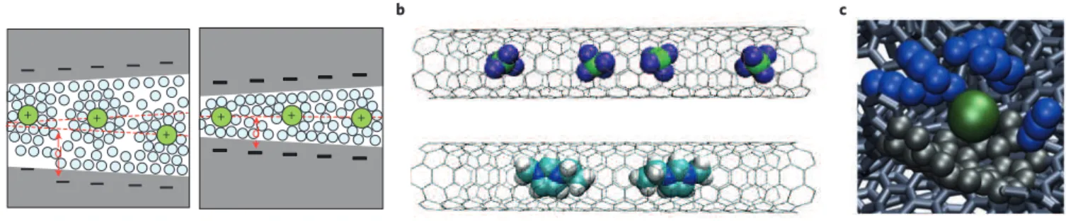
+ + + d d + + + a b c
Figure 7 | Evolution of the picture of the electrode/electrolyte interface in the past decade. a, Ions (green spheres) surrounded by solvent molecules
(blue spheres) residing in pores with size between 1 and 2 nm (left), and less than 1 nm (right), as pictured in 2006. b, Adsorption of BF4− anions (top)
and 1-ethyl-3-methylimidazolium cations (bottom) inside carbon nanotubes that are positively or negatively charged, as seen in 2010 (green, B; violet, F; turquoise, C; blue, N; white, H; black sticks, C–C bonds of the nanotubes). c, Adsorption of partially desolvated PF6− ion in a disordered nanoporous carbon,
as simulated in 2013 (green, PF6−; blue, acetonitrile molecules; black, C atoms in contact with the anion; black sticks, C–C bonds of the electrode). Figure
References
1. Conway, B. E. Electrochemical Supercapacitors: Scientific Fundamentals and Technological Applications (Springer, 1999).
2. Miller, J. R. & Simon, P. Electrochemical capacitors for energy management. Science 321, 651–652 (2008).
3. Chmiola, J. et al. Anomalous increase in carbon capacitance at pore sizes less than 1 nanometer. Science 313, 1760–1763 (2006).
This paper demonstrates that microporous carbons can be used to maximize the capacitance, owing to the desolvation of the ions in subnanometre pores.
4. Toupin, M., Brousse, T. & Bélanger, D. Charge storage mechanism of MnO2 electrode used in aqueous electrochemical capacitor. Chem. Mater. 16, 3184–3190 (2004).
This paper shows that MnO2-based supercapacitors can achieve
very high specific capacitances, highlighting the importance of pseudocapacitive mechanisms.
5. Simon, P. & Gogotsi, Y. Materials for electrochemical capacitors. Nature Mater. 7, 845–854 (2008).
6. Béguin, F., Presser, V., Balducci, A. & Frackowiak, E. Carbons and electrolytes for advanced supercapacitors. Adv. Mater. 26, 2219–2251 (2014). 7. Raccichini, R., Varzi, A., Passerini, S. & Scrosati, B. The role of graphene for
electrochemical energy storage. Nature Mater. 14, 271–279 (2015). 8. Armand, M., Endres, F., MacFarlane, D. R., Ohno, H. & Scrosati, B.
Ionic-liquid materials for the electrochemical challenges of the future. Nature Mater. 8, 621–629 (2009).
9. Brandt, A., Pohlmann, S., Varzi, A., Balducci, A. & Passerini, S. Ionic liquids in supercapacitors. MRS Bull. 38, 554–559 (2013).
10. Helmholtz, H. Ueber einige Gesetze der Vertheilung elektrischer Ströme in körperlichen Leitern mit Anwendung auf die thierisch-elektrischen Versuche. Ann. Phys. Chem. 165, 211–233 (1853).
11. Eliad, L., Salitra, G., Soffer, A. & Aurbach, D. Ion sieving effects in the electrical double layer of porous carbon electrodes: estimating effective ion size in electrolytic solutions. J. Phys. Chem. B 105, 6880–6887 (2001). 12. Eliad, L., Salitra, G., Soffer, A. & Aurbach, D. On the mechanism of selective
electroadsorption in the pores of carbon molecular sieves. Langmuir
21, 3198–3202 (2005).
13. Wang, S., Minami, D. & Kaneko, K. Comparative pore structural analysis of highly porous graphene monoliths treated at different temperatures with adsorption of N2 at 77.4 K and of Ar at 87.3 K and 77.4 K.
Micropor. Mesopor. Mater. 209, 72–78 (2015).
14. Brunauer, S., Emmett, P. H. & Teller, E. Adsorption of gases in multimolecular layers. J. Am. Chem. Soc. 60, 309–319 (1938). 15. Thommes, M. et al. Physisorption of gases, with special reference to the
evaluation of surface area and pore size distribution. Pure Appl. Chem.
87, 1051–1069 (2015).
16. Kaneko, K., Ishii, C., Ruike, M. & Kuwabara, H. Origin of
superhigh microcrystalline graphitic structures of activated carbons. Carbon
30, 1075–1088 (1992).
17. Setoyama, N., Suzuki, T. & Kaneko, K. Simulation study on the relationship between a high resolution αs-plot and the pore size distribution for activated
carbon. Carbon 36, 1459–1467 (1998).
18. Neimark, A. V., Lin, Y., Ravikovitch, P. I. & Thommes, M. Quenched solid density functional theory and pore size analysis of micro-mesoporous carbons. Carbon 47, 1617–1628 (2009).
This paper provides the theoretical basis of density functional theory, which is now the most used method for characterizing the surface area of microporous carbons.
19. Centeno, T. A., Sereda, O. & Stoeckli, F. Capacitance in carbon pores of 0.7 to 15 nm: a regular pattern. Phys. Chem. Chem. Phys.
13, 12403–12406 (2011).
20. Bandosz, T. J. et al. in Chemistry and Physics of Carbon 41–228 (Marcel Dekker, 2001).
21. Bousige, C. et al. Realistic molecular model of kerogen’s nanostructure. Nature Mater. 15, 576–582 (2016).
22. Forse, A. C. et al. New insights into the structure of nanoporous carbons from NMR, Raman, and pair distribution function analysis. Chem. Mater.
27, 6848–6857 (2015).
23. Palmer, J. C. et al. Modeling the structural evolution of carbide-derived carbons using quenched molecular dynamics. Carbon 48, 1116–1123 (2010).
24. Palmer, J. C. & Gubbins, K. E. Atomistic models for disordered nanoporous carbons using reactive force fields. Micropor. Mesopor. Mater. 154, 24–37 (2012). 25. Wang, H. et al. Real-time NMR studies of electrochemical double-layer
capacitors. J. Am. Chem. Soc. 133, 19270–19273 (2011).
26. Griffin, J. M. et al. In situ NMR and electrochemical quartz crystal microbalance techniques reveal the structure of the electrical double layer in supercapacitors. Nature Mater. 14, 812–819 (2015).
This paper shows, by combining in situ electrochemical and spectroscopy techniques, that different ion adsorption mechanisms can dominate the charging process of supercapacitors depending on the polarization of the electrode.
27. Boukhalfa, S. et al. In-situ small angle neutron scattering revealing ion sorption in microporous carbon electrical double layer capacitors. ACS Nano
8, 2495–2503 (2014).
28. Bañuelos, J. L. et al. Densification of ionic liquid molecules within a hierarchical nanoporous carbon structure revealed by small angle scattering and molecular dynamics simulation. Chem. Mater. 26, 1144–1153 (2014).
29. Deschamps, M. et al. Exploring electrolyte organization in supercapacitor electrodes with solid-state NMR. Nature Mater. 12, 351–358 (2013). 30. Merlet, C. et al. On the molecular origin of supercapacitance in nanoporous
carbon electrodes. Nature Mater. 11, 306–310 (2012).
This paper provides the first quantitative picture of the structure of an ionic liquid adsorbed inside realistically modelled microporous carbon electrodes.
31. Merlet, C. et al. Highly confined ions store charge more efficiently in supercapacitors. Nature Commun. 4, 2701 (2013).
32. Shim, T. & Kim, H. J. Nanoporous carbon supercapacitors in an ionic liquid: a computer simulation study. ACS Nano 4, 2345–2355 (2010).
33. Merlet, C., Forse, A. C., Griffin, J., Frenkel, D. & Grey, C. P. Lattice simulation method to model diffusion and NMR spectra in porous materials. J. Chem. Phys. 142, 094701 (2015).
34. Boukhalfa, S., He, L., Melnichenko, Y. B. & Yushin, G. Small-angle neutron scattering for in situ probing of ion adsorption inside micropores. Angew. Chem. Int. Ed. 52, 4618–4622 (2013).
35. Kondrat, S. & Kornyshev, A. Pressing a spring: what does it take to maximize the energy storage in nanoporous supercapacitors? Nanoscale Horiz.
1, 45–52 (2016).
36. Largeot, C. et al. Relation between the ion size and pore size for an electric double-layer capacitor. J. Am. Chem. Soc. 130, 2730–2731 (2008).
37. Galhena, D. T., Bayer, B. C., Hofmann, S. & Amaratunga, G. A. Understanding capacitance variation in sub-nanometer pores by in situ tuning of interlayer constrictions. ACS Nano 10, 747–754 (2016).
38. Raymundo-Pinero, E., Kierzek, K., Machnikowski, J. & Béguin, F. Relationship between the nanoporous texture of activated carbons and their capacitance properties in different electrolytes. Carbon 44, 2498–2507 (2006). 39. Levi, M. D., Sigalov, S., Aurbach, D. & Daikhin, L. In situ electrochemical
quartz crystal admittance methodology for tracking compositional and mechanical changes in porous carbon electrodes. J. Phys. Chem. C
117, 14876–14889 (2013).
40. Levi, M. D., Salitra, G., Levy, N., Aurbach, D. & Maier, J. Application of a quartz-crystal microbalance to measure ionic fluxes in microporous carbons for energy storage. Nature Mater. 8, 872–875 (2009).
This paper demonstrates that it is possible to monitor the gravimetric response of microporous carbons during the ion adsorption inside the pores.
41. Sigalov, S., Levi, M. D., Daikhin, L., Salitra, G. & Aurbach, D. Electrochemical quartz crystal admittance studies of ion adsorption on nanoporous composite carbon electrodes in aprotic solutions. J. Solid State Electrochem.
18, 1335–1344 (2014).
42. Ohkubo, T. et al. Restricted hydration structures of Rb and Br ions confined in slit-shaped carbon nanospace. J. Am. Chem. Soc. 124, 11860–11861 (2002).
This paper shows that desolvation of aqueous ions occurs under extreme confinement using extended X-ray absorption fine structure experiments.
43. Tsai, W.-Y., Taberna, P.-L. & Simon, P. Electrochemical quartz crystal microbalance (EQCM) study of ion dynamics in nanoporous carbons. J. Am. Chem. Soc. 136, 8722–8728 (2014).
44. Fedorov, M. V. & Kornyshev, A. A. Ionic liquids at electrified interfaces. Chem. Rev. 114, 2978–3036 (2014).
45. Xing, L., Vatamanu, J., Borodin, O. & Bedrov, D. On the atomistic nature of capacitance enhancement generated by ionic liquid electrolyte confined in subnanometer pores. J. Phys. Chem. Lett. 4, 132–140 (2013).
46. Freise, V. Zur theorie der diffusendoppeltschicht. Z. Elektrochem.
56, 822–827 (1952).
47. Kornyshev, A. A. Double-layer in ionic liquids: paradigm change? J. Phys. Chem. B 111, 5545–5557 (2007).
48. Limmer, D. T. et al. Charge fluctuations in nanoscale capacitors. Phys. Rev. Lett.
111, 106102 (2013).
49. Merlet, C. et al. The electric double layer has a life of its own. J. Phys. Chem. C
118, 18291–18298 (2014).
50. Kornyshev, A. A. & Qiao, R. Three-dimensional double layers. J. Phys. Chem. C
51. Gebbie, M. A. et al. Ionic liquids behave as dilute electrolyte solutions. Proc. Natl Acad. Sci. USA 110, 9674–9679 (2013).
52. Perkin, S., Salanne, M., Madden, P. & Lynden-Bell, R. Is a stern and diffuse layer model appropriate to ionic liquids at surfaces? Proc. Natl Acad. Sci. USA
110, E4121 (2013).
53. Bozym, D. et al. Anomalous capacitance maximum of the glassy carbon–ionic liquid interface through dilution with organic solvents. J. Phys. Chem. Lett.
6, 2644–2648 (2015).
54. Lee, A. A., Vella, D., Perkin, S. & Goriely, A. Are room-temperature ionic liquids dilute electrolyte? J. Phys. Chem. Lett. 6, 159–163 (2015).
55. Bazant, M. Z., Storey, B. D. & Kornyshev, A. A. Double layer in ionic liquids: overscreening versus crowding. Phys. Rev. Lett. 106, 046102 (2011).
56. Kondrat, S. & Kornyshev, A. A. Superionic state in double-layer capacitors with nanoporous electrodes. J. Phys. Condens. Matter 23, 022201 (2011).
This paper explains the increase of capacitance in microporous carbons by the formation of image charges on the walls which screen the electrostatic interactions between the ions, leading to the formation of a ‘superionic’ state.
57. Kondrat, S., Georgi, N., Fedorov, M. V. & Kornyshev, A. A. A superionic state in nano-porous double-layer capacitors: insights from Monte Carlo simulations. Phys. Chem. Chem. Phys. 13, 11359–11366 (2011).
58. Griffin, J. M. et al. Ion counting in supercapacitor electrode using NMR spectroscopy. Faraday Discuss. 176, 49–68 (2014).
59. Pean, C. et al. Confinement, desolvation and electrosorption effects on the diffusion of ions in nanoporous carbon electrodes. J. Am. Chem. Soc.
137, 12627–12632 (2015).
60. Richey, F. W., Dyatkin, B., Gogotsi, Y. & Elabd, Y. A. Ion dynamics in porous carbon electrodes in supercapacitors using in situ infrared spectroelectrochemistry. J. Am. Chem. Soc. 135, 12818–12826 (2013). 61. Prehal, C. et al. Tracking the structural arrangement of ions in carbon
supercapacitor nanopores using in-situ small angle X-ray scattering. Energy Environ. Sci. 8, 1725–1735 (2015).
62. Ilott, A. J., Trease, N. M., Grey, C. P. & Jerschow, A. Multinuclear in situ magnetic resonance imaging of electrochemical double-layer capacitors. Nature Commun.
5, 4536 (2014).
63. Kondrat, S., Wu, P., Qiao, R. & Kornyshev, A. A. Accelerating charging dynamics in subnanometre pores. Nature Mater. 13, 387–393 (2014).
64. He, Y. et al. The importance of ion packing on the dynamics of ionic liquids during micropore charging. J. Phys. Chem. Lett. 7, 36–42 (2016). 65. Pean, C. et al. On the dynamics of charging in nanoporous carbon-based
supercapacitors. ACS Nano 8, 1576–1583 (2014).
66. Augustyn, C., Simon, P. & Dunn, B. Pseudocapacitive oxide materials for high-rate electrochemical energy storage. Energy Environ. Sci. 7, 1597–1614 (2014). 67. Kim, J. W., Augustyn, V. & Dunn, B. The effect of crystallinity on the rapid
pseudocapacitive response of Nb2O5. Adv. Energy Mater. 2, 141–148 (2012).
68. Come, J. et al. Electrochemical kinetics of nanostructured Nb2O5 electrodes.
J. Electrochem. Soc. 161, A718–A725 (2014).
69. Dmowski, W., Egami, T., Swider-Lyons, K. E., Love, C. T. & Rolison, D. R. Local atomic structure and conduction mechanism of nanocrystalline hydrous RuO2
from X-ray scattering. J. Phys. Chem. B 106, 12677–12683 (2002). 70. Augustyn, V. et al. High-rate electrochemical energy storage through Li+
intercalation pseudocapacitance. Nature Mater. 12, 518–522 (2013).
This paper reports on a pseudocapacitance mechanism based on lithium ion intercalation and defines the structural characteristics which are necessary for this process to occur.
71. Brousse, T., Belanger, D. & Long, J. W. To be or not to be pseudocapacitive? J. Electrochem. Soc. 162, A5185–A5189 (2015).
72. Kim, H.-S., Cook, J. B., Tolbert, S. H. & Dunn, B. The development of pseudocapacitive properties in nanosized-MoO2. J. Electrochem. Soc. 162, A5083–A5090 (2015).
73. Simon, P., Gogotsi, Y. & Dunn, B. Where do batteries end and supercapacitors begin? Science 343, 1210–1211 (2014).
74. Augustyn, V. et al. Lithium-ion storage properties of titanium oxide nanosheets. Mater. Horiz. 1, 219–233 (2014).
75. Athouel, L. et al. Variation of the MnO2 birnessite structure upon charge/
discharge in an electrochemical supercapacitor electrode in aqueous Na2SO4
electrolyte. J. Phys. Chem. C 112, 7270–7277 (2008).
76. Wei, W., Cui, X., Chen, W. & Ivey, D. G. Manganese oxide-based materials as electrochemical supercapacitor electrodes. Chem. Soc. Rev. 40, 1697–1721 (2011). 77. Ghodbane, O., Pascal, J.-L. & Favier, F. Microstructural effects on
charge-storage properties in MnO2-based electrochemical supercapacitors.
ACS Appl. Mater. Interfaces 1, 1130–1139 (2009).
78. Ghodbane, O., Ataherian, F., Wu, N.-L. & Favier, F. In situ crystallographic investigations of charge storage mechanisms in MnO2-based electrochemical
capacitors. J. Power Sources 206, 454–462 (2012).
79. Rangom, Y., Tang, X. & Nazar, L. F. Carbon nanotube-based supercapacitors with excellent ac line filtering and rate capability via improved interfacial impedance. ACS Nano 9, 7248–7255 (2015).
80. Zhu, Y. et al. A carbon quantum dot decorated RuO2 network: outstanding
supercapacitances under ultrafast charge and discharge. Energy Environ. Sci.
6, 3665–3675 (2013).
81. Aravindan, V., Gnanaraj, J., Lee, Y. S. & Madhavi, S. Insertion-type electrodes for nonaqueous Li-ion capacitors. Chem. Rev. 114, 11619–11635 (2014).
82. Naoi, K., Ishimoto, S., Isobe, Y. & Aoyagi, S. High-rate nano-crystalline Li4Ti5O12
attached on carbon nano-fibers for hybrid supercapacitors. J. Power Sources
195, 6250–6254 (2010).
83. Naoi, K., Ishimoto, S., Ogihara, N., Nakagawa, Y. & Hatta, S. Encapsulation of nanodot ruthenium oxide into KB for electrochemical capacitors. J. Electrochem. Soc. 156, A52–A59 (2009).
84. Naoi, K., Ishimoto, S., Miyamoto, J. & Naoi, W. Second generation ‘nanohybrid supercapacitor’: evolution of capacitive energy storage devices. Energy Environ. Sci. 5, 9363–9373 (2012).
This paper reports on the perspectives opened by combining a negative graphite electrode of a Li-ion battery with a capacitive porous-carbon positive electrode.
85. Naoi, K., Naoi, W., Aoyagi, S., Miyamoto, J. & Kamino, T. New generation ‘nanohybrid supercapacitor’. Acc. Chem. Res. 46, 1075–1083 (2012). 86. Vatamanu, J. & Bedrov, D. Capacitive energy storage: current and future
challenges. J. Phys. Chem. Lett. 6, 3594–3609 (2015).
87. Lin, T. et al. Nitrogen-doped mesoporous carbon of extraordinary capacitance for electrochemical energy storage. Science 350, 1508–1513 (2015).
88. Curtarolo, S. et al. The high-throughput highway to computational materials design. Nature Mater. 12, 191–201 (2013).
89. Schutter, C., Husch, T., Korth, M. & Balducci, A. Toward new solvents for EDLCs: from computational screening to electrochemical validation. J. Phys. Chem. C
119, 13413–13424 (2015).
90. Pognon, G., Brousse, T., Demarconnay, L. & Bélanger, D. Performance and stability of electrochemical capacitor based on anthraquinone modified activated carbon. J. Power Sources 196, 4117–4122 (2011).
91. Abbas, Q. et al. Strategies to improve the performance of carbon/ carbon capacitors in salt aqueous electrolytes. J. Electrochem. Soc.
162, A5148–A5157 (2015).
92. Pohlmann, S. et al. Mixtures of azepanium based ionic liquids and propylene carbonate as high voltage electrolytes for supercapacitors. Electrochim. Acta
153, 426–432 (2015).
93. Acerce, M., Voiry, D. & Chhowalla, M. Metallic 1T phase MoS2 nanosheets as
supercapacitor electrode materials. Nature Nanotech. 10, 313–318 (2015). 94. Ghidiu, M., Lukatskaya, M. R., Zhao, M. Q., Gogotsi, Y. & Barsoum, M. W.
Conductive two-dimensional titanium carbide ‘clay’ with high volumetric capacitance. Nature 516, 78–81 (2014).
95. Shi, C. Y. et al. Structure of nanocrystalline Ti3C2 MXene using atomic pair
distribution function. Phys. Rev. Lett. 112, 125501 (2014). 96. Levi, M. D. et al. Solving the capacitive paradox of 2D MXene using
electrochemical quartz-crystal admittance and in situ electronic conductance measurements. Adv. Energ. Mater. 5, 1400815 (2015).
97. Soloveichik, G. L. Flow batteries: current status and trends. Chem. Rev.
115, 11533–11558 (2015).
98. Kwon, C.-H. et al. High power biofuel cells textiles from woven biscrolled carbon nanotube yarns. Nature Commun. 5, 3928 (2014).
99. Presser, V. et al. The electrochemical flow capacitor: a new concept for rapid energy storage and recovery. Adv. Energ. Mater. 2, 895–902 (2012). 100. Brogioli, D. Extracting renewable energy from a salinity difference using a
capacitor. Phys. Rev. Lett. 103, 058501 (2009).
101. Siria, A. et al. Giant osmotic energy conversion measured in a single transmembrane boron nitride nanotube. Nature 494, 455–458 (2013). 102. Wang, J. Carbon nanotube based electrochemical biosensors. Electroanalysis
17, 7–14 (2005).
103. Mirica, K. A., Azzarelli, J. M., Weis, J. G., Schnorr, J. M. & Swager, T. M. Rapid prototyping of carbon-based chemiresistive gas sensors on paper. Proc. Natl Acad. Sci. USA 110, E3265–E3270 (2013).
Acknowledgements
We thank our many co-workers who have contributed to the work presented in this review. C.P.G. thanks J. Griffin for his critical reading of the manuscript. The research leading to these results has received funding from the European Research Council under the European Union’s Seventh Framework Programme (FP/2007-2013)/ ERC grant agreement no. 102539.
Additional information
Reprints and permissions information is available online at www.nature.com/reprints. Correspondence should be addressed to P.S.
Competing interests