DOCTORAT DE L'UNIVERSITÉ DE TOULOUSE
Délivré par :
Institut National Polytechnique de Toulouse (Toulouse INP)
Discipline ou spécialité :
Génie des Procédés et de l'Environnement
Présentée et soutenue par :
Mme FLAVIE PREZELUSle mardi 22 octobre 2019
Titre :
Unité de recherche : Ecole doctorale :
Ecodesign of ultrafiltration membranes for drinking water production: an
experimental and modelling approach
Mécanique, Energétique, Génie civil, Procédés (MEGeP)
Laboratoire de Génie Chimique ( LGC)
Directeur(s) de Thèse : M. JEAN-CHRISTOPHE REMIGY
MME LIGIA BARNA
Rapporteurs :
M. DENIS BOUYER, UNIVERSITE MONTPELLIER 2 Mme GENEVIÈVE GESAN GUIZIOU, INRA RENNES
Membre(s) du jury :
M. DENIS ROIZARD, CNRS, Président
M. BENOIT TEYCHENE, UNIVERSITE DE POITIERS, Membre M. JEAN-CHRISTOPHE REMIGY, UNIVERSITE TOULOUSE 3, Membre
Mme CHRISTELLE GUIGUI, INSA TOULOUSE, Membre Mme LIGIA BARNA, INSA TOULOUSE, Membre
ABSTRACT
Although ultrafiltration treatment processes are widely used for drinking water applications, their environmental performances remain poorly understood. The objectives of this work are to provide understanding of membrane environmental footprint, as well as to suggest and implement relevant innovative solutions for its mitigation.
A multiphase ecodesign approach is applied to hollow fibres fabricated by phase inversion and operated in a dead-end mode. The two developed parameterized models evaluate environmental impacts during fabrication and operation as a function of operating conditions.
The subsequent Life Cycle Assessment highlights glycerol-related operating conditions as interesting action levers for environmental mitigation of membrane fabrication. However, membrane operation accounts for nearly exclusively all environmental impacts, with electricity production and sodium hypochlorite fabrication as the two main contributors. The analysis also pinpoints the influence of filtration flux.
Since opportunities for biosourced solvents exist, substitution of petrochemical solvents during membrane fabrication is chosen as an improvement strategy. A metrics-based methodological framework is suggested to rationalize sustainable membrane fabrication. Biosourced flat membranes using methyl lactate as a solvent have thus been prepared. The mixed environmental scores do not preclude solvent substitution as a relevant improvement strategy.
Results highlight the feasibility and relevance of such an ecodesign approach based on process modelling and experimental work, and lay the foundations for further development.
Keywords: Process modelling − Life cycle assessment (LCA) – Ecodesign – Phase inversion −
RÉSUMÉ
Les procédés de traitement par ultrafiltration sont certes largement utilisés pour la production d’eau potable mais leurs performances environnementales restent néanmoins mal connues. Ce travail vise à une meilleure compréhension de l’empreinte environnementale des membranes, ainsi qu’à la proposition et mise en œuvre de solutions innovantes et pertinentes afin de l’atténuer.
Une approche multi-étapes d'écoconception est appliquée aux fibres creuses fabriquées par inversion de phase et utilisées en filtration frontale. Deux modèles paramétrés ont été développés pour évaluer les impacts environnementaux lors des étapes de fabrication et d'utilisation en fonction des conditions opératoires.
L’analyse de cycle de vie a mis en évidence que les conditions opératoires liées au glycérol étaient des leviers d’action intéressants pour l’étape de fabrication. La quasi-exclusivité des impacts environnementaux est toutefois liée à l’étape d’utilisation, pour laquelle la production d’électricité et la fabrication d’hypochlorite de sodium sont les deux principaux contributeurs. L'analyse montre également l'influence du flux de filtration.
Des opportunités existent concernant l’utilisation de solvants biosourcés, d’où la stratégie d’amélioration qui consiste à remplacer les solvants d’origine pétrochimique lors de la fabrication membranaire. Un cadre méthodologique basé sur des indicateurs a été proposé afin de rationaliser la fabrication de membrane durable. Des membranes planes biosourcées ont ainsi été obtenues en utilisant le lactate de méthyle comme solvant. Les résultats environnementaux mitigés n'excluent pas pour autant le remplacement de solvant en tant que stratégie d'amélioration.
Les résultats soulignent la faisabilité et la pertinence de cette approche d'écoconception basée sur la modélisation de procédé et le travail expérimental, et posent les bases des améliorations futures.
Mots-clés : Modélisation de procédés − Analyse de cycle de vie (ACV) − Écoconception – Inversion de
Article paru dans un journal international à comité de lecture
Prézélus, F., Chabni, D., Barna, L., Guigui, C. & Remigy, J. C. (2019). A metrics-based approach to
preparing greener membranes: application to ultrafiltration. Green Chemistry, 21, 4457-4469. DOI: 10.1039/c9gc01178a.
Communications avec actes et à comité de lecture dans des congrès internationaux
Prézélus, F., Chabni, D., Barna, L., Guigui, C., & Remigy, J. C. (2018). Eco-design for membrane
elaboration and drinking water process. EuroMembrane, 9 – 13 July 2018, Valence.
Prézélus, F., Chabni, D., Barna, L., Guigui, C. & Remigy, J. C. (2018). Eco-design of ultrafiltration
membranes for drinking water application. 6th International Congress on Green Process Engineering, 3 – 6 June 2018, Toulouse.
Prézélus, F., Chabni, D., Barna, L., Guigui, C., & Remigy, J. C. (2017). Écoconception de membrane
d’ultrafiltration. 6ème édition du congrès MemPro, 7 – 9 June 2017, Saint-Malo.
Prézélus, F., Barna, L., Guigui, C., & Remigy, J. C. (2017). Replacing toxic solvent for filtration
Merci…
Ce manuscrit est le fruit d’un long travail qui a été rendu possible grâce à l’implication, au soutien et à la passion de nombreuses personnes côtoyées au cours de cette thèse. Mes premiers remerciements vont ainsi aux deux établissements qui m’ont accueillie et permis de réaliser ce travail dans un environnement propice aux rencontres et aux échanges : le Laboratoire de Génie Chimique (LGC) et le Toulouse Biotechnology Institute (TBI ‒ nommé LISBP il y a peu). Merci notamment à Pierre Aimar, directeur du LGC, qui garde sa porte toujours ouverte.
Je souhaite exprimer toute ma gratitude et ma reconnaissance envers Jean-Christophe, Ligia et Christelle, vous qui m’avez accordé votre confiance pour ce projet et encadrée en toute bienveillance. De par vos compétences scientifiques et votre humanité, vous avez contribué chacun à votre manière à rendre ces années de thèse inoubliables.
Jean-Christophe, je te remercie pour ta disponibilité et la sérénité avec laquelle t’abordes le travail, ç’en est contagieux ! Ton pragmatisme et ta prise de recul m’ont plus d’une fois éclairée lors de nos réunions et aidée à aller à l’essentiel. Ligia, merci pour ton empathie ainsi que de mettre un point d’honneur à faire avancer les choses : proposer des solutions concrètes, prendre position, corriger plus vite que ton ombre et j’en passe… Christelle, merci aussi à toi pour tes conseils avisés sur ce sujet de thèse qui te tient à cœur et pour la perspicacité de tes remarques qui m’ont permis de progresser dans mes réflexions.
Je tiens à remercier Philippe qui, même si absent de la page de garde de ce manuscrit, s’est impliqué comme un quatrième encadrant l’aurait peut-être fait. Tu as participé à une majorité des réunions, à chaque fois muni de ta gentillesse, ta passion pour les membranes et d’une source inépuisable d’idées.
Merci à tous les membres du jury pour l’intérêt que vous avez porté à ce travail et à votre contribution aux discussions scientifiques enrichissantes lors de la soutenance. En particulier, merci à Denis Bouyer et Geneviève Gésan-Guiziou d’avoir accepté d’être rapporteur et rapporteuse de cette thèse, à Denis Roizard d’avoir présidé ce jury avec bonne humeur, à Benoît Teychené d’en avoir été examinateur, et à Patrick Sauvade d’avoir apporté son regard d’industriel. Ton implication dans cette thèse ne s’est d’ailleurs pas limitée à ta participation en tant qu’invité ; je te remercie vivement pour les échanges fructueux que l’on a pu avoir, les premiers remontant au tout début de ma thèse. C’est en grande partie grâce à ta volonté de partager tes connaissances que la partie sur la fabrication membranaire dans ce manuscrit a pu prendre une dimension industrielle.
Cette dimension industrielle repose également sur l’implication d’autres collaboratrices et collaborateurs de Suez : Angélique Fabre, Max Faure, Anne Brehant. Mention spéciale pour Daniel Bourdiol pour qui le fonctionnement d’une usine d’eau potable n’a aucun secret, c’était un plaisir de t’entendre parler avec enthousiasme de ce sujet. Merci aussi à Nouhad Abidine d’ABC Membranes d’avoir toujours répondu présent pour apporter ton aide (polymère, information…).
Cette thèse impliquait une partie expérimentale : fabrication de membranes, leur caractérisation, analyse de l’eau… J’ai eu la chance de pouvoir m’appuyer sur les équipes techniques de chaque laboratoire, qui m’ont formée et aidée à chaque étape. Côté LGC, c’est avec une pointe de nostalgie que je pense à mes premières membranes fabriquées avec Jean-Christophe (Rouch). Ça m’a toujours étonnée que tu te souvenais comme si c’était hier des moindres détails de la fabrication industrielle d’il y a plusieurs décennies. Merci à Sandrine pour les mesures de perméabilité et Brigitte pour les analyses chromatographiques. Côté TBI/LISBP, merci à Aurore pour les analyses d’eau et Manon pour la partie filtration membranaire. Bonne humeur et disponibilité sont vos maîtres-mots !
Je n’oublie évidemment pas l’aide de Dihia, qui m’a épaulée avec dynamisme au cours de son stage et à qui j’ai pu faire confiance pour mener jusqu’au bout la fabrication de membranes biosourcées. Je te souhaite autant de réussite pour ta thèse.
Cette période en thèse m’a aussi permis de partager la présidence de l’Alambic avec Jesús. Merci à toi et à toute l’équipe ‒ Claire, Hélène, Melissa, Leticia, Silvia, Emanuel, Alexandre, Paul, Magno ‒ d’avoir contribué à faire vivre l’association et à créer du lien au sein du LGC. Qui dit Alambic dit Alain, merci pour ton aide précieuse, tu connais les locaux à Labège comme ta poche !
Des liens se sont aussi créés hors Alambic, je tiens ainsi à remercier les (post-)doctorants pour la bonne ambiance générale qui régnait dans les deux laboratoires et permettait d’alterner entre moments de détente et de soutien mutuel. Les « anciens » ont donné l’exemple ‒ Arthur, Johanne, Melissa, Emelyne, Hugo ‒ tandis que les « nouveaux » sont sur la bonne voie ‒ Ryma, Dylan, Alexandre, Marine. Je vous souhaite courage et persévérance !
Mylène et Juan, cette aventure à Toulouse a commencé au détour d’un coup de fil ! Merci à vous de m’avoir accueillie avant même que la thèse démarre et de m’avoir permis de rencontrer la team « rue Léonard de Vinci » au sens (très) large du terme : Alexandre, Doriane, Kévin, Vivien, Claire R., Claire M…. Que de très bons moments partagés avec vous, que ce soit à la coloc, en ville, en vadrouille pour le weekend, lors de soirées jeux de plateaux… Un merci particulier à Léo et Marco avec qui le quotidien s’est trouvé égayé !
J’ai aussi la chance d’être entourée de fidèles amies et amis, merci pour vos encouragements et les bouffées d’oxygène que vous m’avez apportées. Je pense à Aude (peu importe la distance, le continent !), Elise (gardons notre gaieté :b), Ophélie (vive les salons de coiffure et leurs devantures improbables) et bien sûr aux gastronomes spécialisés dans les noisettes (mais pas que) : Cléo, Jess, Sébastien, Léa, Aïda, Alice, Jérôme, Maud, Coralie, François.
Merci aussi à ma famille, qui m’a apportée son soutien indéfectible et son amour inconditionnelle tout au long de ces nombreuses années ; merci à mes parents, mes grands-parents, mon frère et à ma sœur d’avoir été présents en ce jour de soutenance si important pour moi et/ou après pour fêter ça ! Merci à Arlette, Nicole et Patrick de m’avoir fait le plaisir d’assister à la soutenance et, plus largement, de m’avoir fait une place dans leur famille.
Claire, mes derniers mots de remerciements te reviennent ! Toi qui m’as encouragée, soutenue voire parfois supportée au quotidien, toi qui partage ma vie et que j’aime, comment ne pas te dire merci pour ton sens de l’écoute, ton humour, ta façon d’être toi…
GENERAL INTRODUCTION 1 CHAPTER I. STATE OF THE ART
1 From raw water to drinking water
1.1 Quality of raw water
1.2 Conventional water treatment 1.3 Membranes for water treatment
2 Fabrication of organic membranes and modules
2.1 Types of membranes and modules 2.2 Membrane fabrication methods
2.3 Hollow fibre fabrication process by NIPS 2.4 Towards sustainable UF membranes
3 UF process in drinking water treatment
3.1 UF technology in a water treatment process 3.2 Membrane fouling
3.3 Cleaning techniques to reverse fouling 3.4 Modelling UF membrane systems
4 Ecodesign applied to membrane systems
4.1 Introduction
4.2 Towards sustainable UF water treatment processes 4.3 Conclusion
5 Study objectives and methodology
3 3 5 6 7 7 9 10 15 19 19 20 22 26 28 28 30 33 34
CHAPTER II. MODELLING MEMBRANE FABRICATION AND OPERATION 1 Modelling hollow fibre and module fabrication
1.1 Module in the model 1.2 Process in the model 1.3 Model assumptions
2 Modelling membrane operation
2.1 Model framework
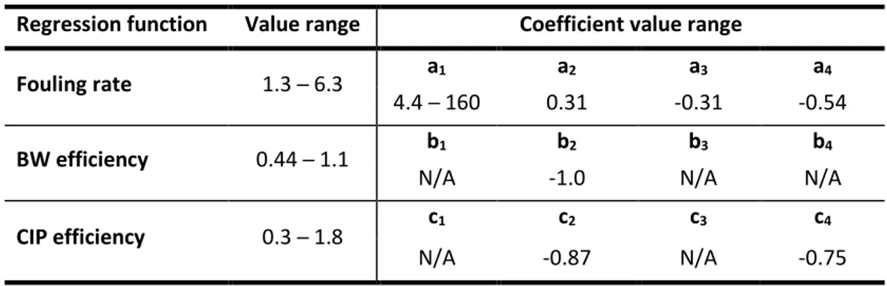
2.2 Model regression functions 2.3 Model simplifications
2.4 Determination of regression function coefficients 2.5 Model calculations 2.6 Model initialization 37 37 38 42 48 48 62 67 69 71 72
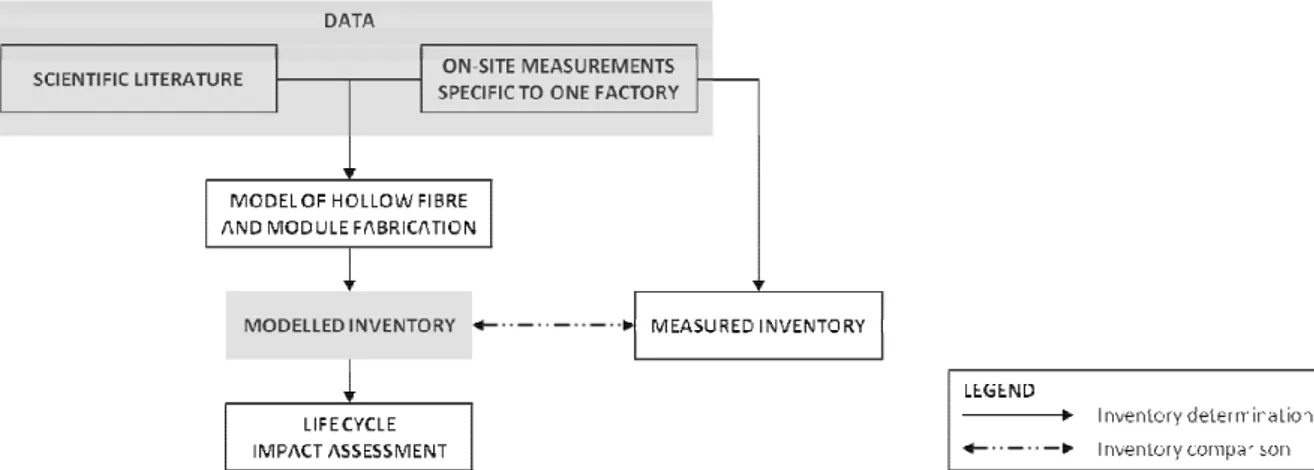
CHAPTER III. ENVIRONMENTAL EVALUATION OF MEMBRANE FABRICATION AND OPERATION 1 LCA of conventional hollow fibre and module fabrication
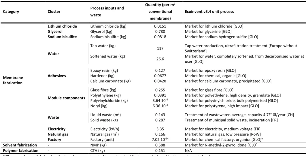
1.1 Goal and scope 1.2 Inventory analysis 1.3 Inventory comparison 1.4 CTA inventory
1.5 Impact assessment
1.6 LCA results and interpretation 1.7 Sensitivity analysis
1.8 Conclusions
2 LCA of conventional membrane operation
2.1 Goal and scope
2.2 Inventory analysis and impact assessment 2.3 Inventory comparison
2.4 LCA results and interpretation 2.5 Sensitivity analysis
2.6 Conclusions
3 LCA of conventional membranes
3.1 Goal and scope
3.2 Inventory analysis and impact assessment 3.3 LCA results and interpretation
3.4 Conclusions 79 79 79 80 84 85 88 93 96 97 97 97 98 100 102 106 108 108 108 109 112
CHAPTER IV. FABRICATION OF SUSTAINABLE MEMBRANES 1 Introduction
2 A metrics-based framework for membrane fabrication 3 Performances of fabricated biosourced membranes 4 Conclusion
113 113 127 127
CHAPTER V. COMPARATIVE ANALYSIS BETWEEN BIOSOURCED AND CONVENTIONAL MEMBRANE FABRICATION
1 LCA of methyl lactate fabrication
1.1 Inventory analysis
1.2 LCA results and interpretation 1.3 Sensitivity analysis
1.4 Methyl lactate vs NMP fabrication
2 LCA of CDA fabrication
2.1 Inventory analysis 2.2 CDA vs CTA fabrication
3 LCA of biosourced vs conventional membrane fabrication
3.1 Goal and scope 3.2 Inventory analysis
3.3 LCA results and interpretation 3.4 Sensitivity analysis 4 Conclusions 130 130 134 136 138 140 140 140 142 142 142 145 147 150
CONCLUSIONS AND PERSPECTIVES 151
BIBLIOGRAPHIC REFERENCES 155
APPENDICES
II−1 Hollow fibre and module fabrication – Modelling equations II−2 Hollow fibre and module fabrication – Values
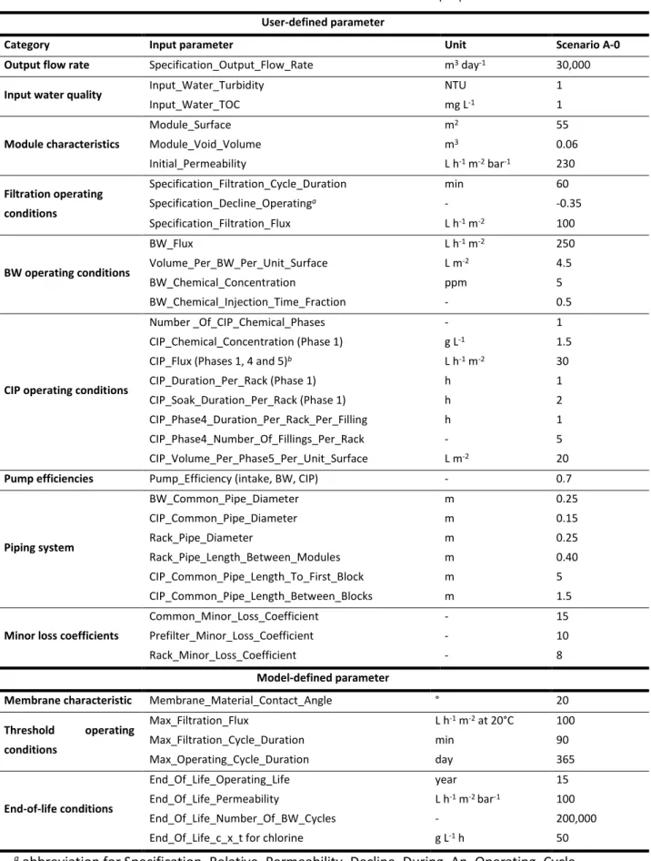
II−3 Hollow fibre and module fabrication – Thermal transfer efficiencies II−4 Membrane operation – Model input parameters
II−5 Membrane operation – Categories of input water quality II−6 Membrane operation – Membrane end-of-life conditions
II−7 Membrane operation – Neglected BW and CIP chemical injection II−8 Membrane operation – Values for regression functions
III−1 Calculation of CA inventory
IV−1 Calculation of methyl lactate inventory
171 171 204 216 221 224 225 226 227 233 240
LIST OF TABLES AND FIGURES 257
1
Human societies undeniably transform and leave a footprint on our planet Earth. In November 2017 in BioScience, the Union of Concerned Scientists supported by more than 15,000 scientists from 184 countries reiterate their warning to humanity: the 9 indicators of global warming, depletion of natural resources and erosion of biodiversity follow alarming trends. The only significant achievement over the past 25 years is the reduced emissions of stratospheric ozone depleters (Ripple et al., 2017).
The current ecological emergency sets a threefold challenge to the drinking water sector:
1/ Ensure access to water for all despite global resource scarcity. Freshwater resources per capita have declined by 26% in 25 years, almost entirely due to rapid population growth (Ripple et al., 2017). Freshwater available as groundwater and surface water (rivers, lakes) represents only 0.8% of the total water resources on our blue planet (Anctil, 2017).
2/ Guarantee quality of treated water despite resource degradation. Agricultural, domestic and industrial activities emit substances such as pesticides, heavy metals and medicinal residues that contribute to the overall pollution of water resources. Tighter drinking water standards not only reflect advances in analytical chemistry but also echo public health concerns.
3/ Limit environmental impacts of the value chain (i.e. water withdrawal, treatment, distribution, use and disposal). The challenge is to reduce energy and raw materials required to produce higher-quality drinking water from scarcer and more degraded resources: achieve more with less.
Addressing these challenges requires improved water treatment methods: greater flexibility in managing temporary peak demands; constant drinking water quality despite variable resource quality; reduced chemical use during water treatment; reduced physical footprint of treatment methods. The aforementioned technical specifications have led research to consider new technologies, notably membrane-based processes.
In the 1980s, researchers in Toulouse (France) began the adventure of developing ultrafiltration with hollow fibre membranes for water clarification and disinfection (Aptel et al., 1985; Bersillon et al., 1989; Université de Toulouse et al., 2014). In an inside-out dead-end configuration, raw water is circulated under pressure inside hollow fibres (i.e. fibre lumen) through their membrane thickness. Treated water is collected on the outside of fibres while impurities (pathogens, suspended and colloidal matter) are retained. The first ultrafiltration drinking water plant was commissioned in 1988 in Amoncourt (France). Thirty years later, this membrane technology is considered mature and research work now focuses, among other things, on the third stated challenge ─ a challenge based on collective ecological awareness (Coehlo et al., 2019).
2
Armed with this awareness, Région Occitanie and Université de Toulouse have provided financial support for the ECOMEM project. Initiated by the Water Sensors and Membranes cluster, the project is implemented by two laboratories: Laboratoire de Génie Chimique and Toulouse Biotechnology Institute ─ Bio & Chemical Engineering (formerly LISBP). Focus is given to the ecodesign of water filtration membranes and more specifically to ultrafiltration hollow fibres operated in an inside-out dead-end configuration.
Another feature of hollow fibres in our work is their cellulose acetate composition. Owing to its excellent filtration properties and low adsorption of natural organic matter, this material has been used to fabricate the first ultrafiltration drinking water membranes. Daicen Membrane-Systems Ltd. (n.d.) continues to market similar modules (FW50, FZ50 and FN20) for drinking water applications. Toyobo (2006) on the other hand markets cellulose acetate reverse osmosis membranes (HOLLOSEP®). Other fields of application include protein purification, concentration and diafiltration (ultrafiltration cassettes by Sartorius (2019)) and wastewater treatment by forward osmosis (OsmoF2OTM by Fluid Technology Solutions (2017)). Although cellulose acetate has a lower chemical
resistance than petrochemical-based materials, this polymer still arouses interest (Kanagaraj et al., 2016; Yang et al., 2019). Given that our research investigates environmental impacts of water ultrafiltration, it seemed natural to consider the only common biosourced and biodegradable polymer that has well-known performances in the studied application: cellulose acetate.
The ecodesign of such organic membranes entails understanding hollow fibre and module fabrication. Membrane operation and fouling as a major limitation thereof also need to be comprehended and coupled at a further stage with membrane fabrication. The state of the art covers these topics and moreover paves the way for formulating the study objectives and methodology of this work.
1 From raw water to drinking water 3
1.1 Quality of raw water 3
1.1.1 Impurities in raw water and related problems 3
1.1.2 Categories of raw water for water treatment 4
1.2 Conventional water treatment 5
1.3 Membranes for water treatment 6
2 Fabrication of organic membranes and modules 7
2.1 Types of membranes and modules 7
2.1.1 Membrane structure and material 7
2.1.2 Module configuration 8
2.2 Membrane fabrication methods 9
2.3 Hollow fibre fabrication process by NIPS 10
2.3.1 Thermodynamics and kinetics 10
2.3.2 Main operating conditions 12
2.3.3 Industrial process 13
2.4 Towards sustainable UF membranes 15
2.4.1 Stakes and issues 15
2.4.2 Toxic solvent substitution 16
2.4.3 Petrochemical polymer substitution 16
2.4.4 Conclusion 17
3 UF process in drinking water treatment 19
3.1 UF technology in a water treatment process 19
3.1.1 UF as unit operation 19
3.1.2 Module configuration 19
3.2 Membrane fouling 20
3.2.1 Influence of water quality 20
3.2.2 Influence of membrane properties 21
3.2.3 Influence of filtration conditions 22
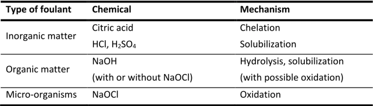
3.3 Cleaning techniques to reverse fouling 22
3.3.1 Physical cleaning: backwash (BW) 22
3.3.2 Chemical cleaning: clean-in-place (CIP) 23
3.3.3 Defining BW and CIP efficiency 24
3.3.4 Influence of BW conditions on BW efficiency 24
3.3.5 Influence of CIP conditions on CIP efficiency 25
3.4 Modelling UF membrane systems 26
3.4.1 Resistance-in-series model and fouling mechanisms 26
3.4.2 Statistical approach to describe fouling and remediation efficiency 27
4 Ecodesign applied to membrane systems 28
4.1 Introduction 28
4.2 Towards sustainable UF water treatment processes 30
4.2.1 UF membranes in LCA studies 30
4.2.2 Main contributors to environmental impacts 31
4.2.3 Incomplete study of module fabrication 31
4.2.4 Need for studies with variable operating conditions 32
4.3 Conclusion 33
3
This chapter first explains the need to treat raw water for drinking water purposes and how membrane-based processes overcome limitations of conventional processes. Membrane fabrication and operation are then detailed with a focus on research initiatives towards sustainability of both ultrafiltration (UF) membranes and their associated water treatment processes. In particular, ecodesign applied to membrane systems is developed and leads to expliciting the study objectives and methodology of this work.
1 FROM RAW WATER TO DRINKING WATER
1.1QUALITY OF RAW WATER
1.1.1 Impurities in raw water and related problems
Raw water extracted from surface or groundwater is composed of a complex matrix of chemical substances. Biological, mineral and organic matter is naturally found in water as a result of surface run-off and infiltration. Rock weathering, soil leaching and decomposition of animal and plant debris are among common origins of impurities found in water. Anthropogenic activities also significantly impact on the composition of raw water, for instance, through discharge of wastewater, agricultural and industrial waste. Table I.1 summarizes common examples of impurities found in raw water.
Table I.1 Common examples of biological, mineral and organic impurities
Nature of impurity
Biological Mineral Organic
Bacteria Virus Protozoa Algae and toxins
Sand, silt, clay Iron, manganese Nitrate, nitrite, sulphate
Natural organic matter (humic substances, proteins, polysaccharides)
Pesticides
Polycyclic aromatic hydrocarbons
Raw water with impurities above acceptable limits is considered unfit for human consumption due to unmet organoleptic requirements (taste, odour, colour) and most importantly to public health risks. It should be noted that these drinking water criteria not only vary from one country to another but have also evolved over time with the development of analytic methods. Exhaustive lists of drinking-water parameters and limits can be found in national regulations, generally more restrictive than international guidelines edited by the World Health Organization (2011). In what follows, focus is made on three major types of impurity:
- Pathogenic impurities (bacteria, virus, protozoa); - Natural organic matter;
- Colloids.
The greatest short-term threat to human health from water consumption comes from pathogenic
impurities. As shown in Table I.2, several species of bacteria, virus and protozoa can be transmitted
4
Table I.2 Major pathogenic impurities and associated water-borne diseases (adapted from WHO, 2011)
Pathogen Water-borne disease
Bacteria
Escherichia coli Gastroenteritis
Legionella Legionellosis
Salmonella Typhoid, gastroenteritis
Shigella Dysentery, gastroenteritis
Vibrio cholerae Cholera
Virus
Hepatitis A and E virus Hepatitis A and E Enterovirus
Gastroenteritis Rotavirus
Protozoa Cryptosporidium Gastroenteritis Giardia intestinalis
Natural organic matter (NOM), derived from decomposed animal and plant debris, is found in both
dissolved and particulate form in raw water. Particulate organic matter is retained by a 0.45 µm filter whereas dissolved organic matter is not. The main concern of their presence is related to the formation of disinfection by-products during water treatment. Organic matter reacts with halogens (typically chlorine) to form trihalomethanes, many of which are carcinogenic (e.g. chloroform). Organic colour of water is often associated with humic substances, an important component of NOM that can be divided into three fractions: humic acids which precipitate below pH 2; fulvic acids which remain soluble irrespective of pH; and humins which are insoluble at any pH (Thurman & Malcom, 1981).
Colloids are defined according to size and not according to their microbiological or chemical nature.
Colloids are electrically-charged particles inferior to 1 µm and impact on water colour and turbidity. Special focus is needed during water treatment because their small size results in a low effect of gravitational forces during settlement and electrostatic repulsion between particles prevents the formation of larger particles through coalescence.
The appropriate water treatment process depends on the presence and quantity of pathogenic impurities, NOM, colloids and other impurities. Given the variety and variability of raw water quality, decision-makers and water suppliers feel the need to categorize raw water and relate to relevant degrees of treatment.
1.1.2 Categories of raw water for water treatment
As of 1975, surface water in the European Union intended for drinking water production was categorized according to 43 physical, chemical and microbiological parameters (directive 75/440/EEC). Three categories defined the required treatment:
5
- Category A2: normal physical treatment, chemical treatment and disinfection;
- Category A3: intensive physical and chemical treatment, extended treatment and disinfection. Whilst the new framework (2000/60/EC) places more emphasis on the prevention of water pollution and preservation of water bodies, the curative approach of the 1975 Directive based on restrictive limit values corresponds more closely to water suppliers core business, namely by clarifying the relationship between raw water quality and water treatment.
Crozes (1994) further studied relationships between raw water quality and water treatment operating conditions based on statistical analysis of data obtained from pilot trials. Seven raw water categories have been suggested with corresponding operating conditions for membrane separation (flux, transmembrane pressure (TMP), filtration duration...). The most discriminating parameters for this classification are the nature and quantity of NOM, determined by UV254 nm and total organic
carbon (TOC) measurements. Nowadays, water suppliers still use such categories as sizing and operating tool for drinking water plants.
1.2CONVENTIONAL WATER TREATMENT
Conventional water treatment of both surface and groundwater can be divided into four chronological stages detailed below.
I. PRELIMINARY TREATMENT
Screening removes solids down to 1 mm. High levels of iron and manganese in groundwater can be treated by pre-oxydation with chlorine or oxygen. Pre-chlorination of surface waters is no longer a current practice due to risks related to trihalomethane formation.
II. CLARIFICATION
The sequence of physico-chemical unit operations (coagulation-flocculation-settlement followed by sand filtration) aims as the destabilization and separation of colloids, along with the removal of larger suspended particles.
III. EXTENDED TREATMENT
Ozonation and filtration with granular activated carbon (GAC) media are sometimes needed to remove pesticides and any remaining NOM.
IV. DISINFECTION
Pathogens are killed or inactivated with chlorine-releasing compounds (chlorine, chloramine, chlorine dioxide) or UV radiation. A residual disinfectant is added so that water remains pathogen-free through the distribution system.
Conventional water treatment and its successive unit operations are widely used but are nonetheless subject to major limitations:
6
- Drinking water from such a process can be of variable quality due to variable raw water quality and the interdependence of unit operations as regards their performance. Adjusting the chemical dosage to input load with precision during coagulation and flocculation may prove to be technically difficult. Poor colloidal destabilization limits performances of sand filtration and disinfection. Overall turbidity and colour of drinking water are affected;
- The use of chemicals is necessary for the removal of colloids due to their size and chemical nature;
- Toxic by-products may form during disinfection in the presence of remaining NOM; - Infrastructures, especially settling basins, can have a large physical footprint.
1.3MEMBRANES FOR WATER TREATMENT
As of the 1980s, limitations of conventional water treatment have led researchers to investigate on the use of membranes to treat freshwater (Bersillon et al., 1989; Cabassud et al., 1991; Clark & Heneghan, 1991; Jacangelo et al., 1997; Laîné et al., 2000). In 1988, the first UF drinking water plant was inaugurated in France (Amoncourt, 10 m3 h-1). Nowadays membrane technology for drinking
water applications is a mature technology notably owing to the: - Constant quality of treated water;
- High-quality treated water as compared to that obtained with conventional water treatment, which moreover meets more stringent potable-water standards;
- Physical nature of the treatment, thereby avoiding chemical inputs and formation of disinfection by-products;
- Technology compacity.
UF is the most common variety of membrane filtration used for freshwater potabilization. This pressure-driven filtration process separates particles in the range of 1 to 100 nm, which includes suspended and colloidal matter, and pathogenic impurities except for the smallest species of virus.
As discussed in the following sections, UF membranes in drinking water plants are primarily self-supported hollow fibres based on a porous organic structure.
7
2 FABRICATION OF ORGANIC MEMBRANES AND MODULES
Organic filtration membranes represent more than 80% of the membrane market. They can be cheaply fabricated in various geometries and pore sizes as opposed to mineral membranes (ceramic, porous carbon, metal, glass...) that are only available as tubular or flat-shaped and limited to microfiltration (MF) and UF. Although mineral membranes offer greater chemical, mechanical and thermal resistances than organic ones, their high investment cost is a major constraint on commercial development. At this point in time, organic membranes are more appropriate for low value-added applications such as drinking water treatment.
2.1TYPES OF MEMBRANES AND MODULES
2.1.1 Membrane structure and material
Depending on the target application and consequent fabrication method, three types of membrane structures can be obtained: symmetric, asymmetric (anisotropic) and composite.
Symmetric and asymmetric membranes are both composed of a single material. Symmetric membranes (porous or dense) have a uniform pore size along the membrane's thickness, whereas asymmetric membranes are made up of one or two selective layers and a porous support layer. The selective layer sets the membrane's selectivity and permeability: it has the smallest pore size and lowest porosity. The mass transport rate is also inversely proportional to the layer's thickness. In this sense, asymmetric membranes' thin selective layer offers reduced resistance to mass transport compared to symmetric membranes. The support layer does not influence on the mass transport rate or selectivity but solely provides mechanical strength. Composite membranes are composed of several layers of different materials and porosities. Resistance to mass transport is further reduced thanks to an even thinner selective layer.
Membrane material impacts on the selective layer's performances as well as the overall membrane's resistance to heat flow and exposition to chemicals. Resistance to mechanical stress partly depends on membrane material, two other important factors being membrane structure and geometry.
Organic membranes consist of polymeric matrices. Common polymers used for filtration membranes can be classified in classes: cellulosic derivatives, polysulfones, polyamides, polyolefins including fluorinated derivatives, polycarbonate, acrylic derivatives (grafted or as copolymers) and other polymers used as additives or membrane surface modifiers.
Although a variety of polymers exist for filtration membranes, only four dominate the UF market of drinking water treatment: cellulose triacetate (CTA), polyethersulfone (PES), polysulfone (PS) and polyvinylidene fluoride (PVdF).
8 - CTA membranes are easy to fabricate;
- The raw material for CTA, cellulose, is abundant, biosourced and cheap; - Both high permeability and selectivity are obtained;
- Fouling by adsorption, in particular of NOM, is low. Notable limitations in CTA use exist (Cheryan, 1986):
- The pH range is limited from 2 to 8. Acidic and alkaline conditions accelerate hydrolysis of the cellulose backbone and acetyl groups respectively. Operating and cleaning within a limited pH range maintains membrane integrity and performances;
- Temperature is limited to a maximum of 30°C. Temperature accelerates hydrolysis reaction rates leading to reduced membrane lifespan;
- Chlorine concentration and exposure time need to be carefully controlled so as to avoid CTA oxidation. Suggested thresholds are 1 mg L-1 for continuous injection and 50 mg L-1 for an
hour-long shock dose;
- Microbial proliferation also needs to be controlled because CTA can easily be biodegraded. Disinfectant agents such as chlorine can be used, in compliance with recommended concentrations and exposure times.
PS, PES and PVdF have greater thermal and chemical resistances than CTA. Continuous operation at 75°C or with a pH from 1 to 12 is for example possible (Arkema, n.d.; Cheryan, 1986). Polysulfones can respectively withstand 5 mg L-1, 50 mg L-1 and200 mg L-1 for continuous injection, long-term
storage and short-term shocks (Cheryan, 1986). Unlike CTA however, these three membrane materials are prone to greater fouling by adsorption. Fouling affects membrane productivity and calls for preventive and curative measures. The question arises of whether less fouling by adsorption offsets limitations in thermal and chemical conditions. Although industrial choices have been made, not all aspects (technical, environmental, economic...) of this question have been addressed.
2.1.2 Module configuration
Fabricated membranes are assembled into modules for membrane filtration. Module geometry depends on membrane geometry: tubular, hollow fibre and flat. Tubular and hollow fibre membranes are cylindrical-shaped tubes with different dimensions (see Figure I.1). A tubular module consists of one or more parallel tubes, whereas a hollow fibre module contains several dozens to thousand parallel fibres. Flat membranes can be either stacked into a plate-and frame module or rolled around a tube to form a spiral-wound module.
9
Figure I.1 Internal diameters of hollow fibre and tubular membranes (adapted from Porter, 1989)
Compact hollow fibre modules (up to 15,000 m2 m-3) with low dead volumes are obtained due to the
small internal diameter of hollow fibres (less than 3 mm). Investment and energy costs are also relatively low compared to other module configurations (see Table I.3). The membrane structure makes it possible to wash hollow fibres with a counter-current flow. Pretreatment to 80-150 µm is required to avoid particles from plugging internal channels, in contrast to 5 µm or less for spiral-wound modules.
Table I.3 Comparison between module geometries (adapted from Pearce, 2011)
Module Membrane Compactness
(m2 m-3) Investment cost Energy cost for pumping Cleaning difficulty Required pretreatment Tubular Tubular 10 – 300 ++ +++ + +
Plate and frame
Flat 100 – 400 ++ ++ +/++ ++
Spiral-wound 300 – 1,000 + + ++/+++ ++
Hollow fibre Hollow fibre 1 000 – 15,000 + + ++ +/++
Legend: + low, ++ moderate, +++ high .
These interesting features provide an explanation to the 95% use of hollow fibre modules in drinking water treatment applications.
2.2MEMBRANE FABRICATION METHODS
The most common industrial membrane fabrication method is phase separation. MF to reverse osmosis (RO) membranes can be obtained with a wide variety of characteristics that can be adjusted by changing operating conditions. The prerequisite for the method is that the polymer be soluble in at least one solvent. The polymer is indeed first dissolved in a solvent. The resulting homogeneous polymer solution is either cast on a planar support to obtain flat membranes or extruded to obtain hollow fibres. A change of thermodynamic state of the polymer solution causes its separation into two phases: a polymer rich phase that solidifies into the membrane structure and a polymer lean phase that creates the porous structure. Three types of phase separation can be distinguished according to how the change from a soluble to insoluble polymer is induced:
- Non-solvent induced phase separation (NIPS): a binary solvent/polymer solution is immersed in a liquid non-solvent. The latter must be miscible with the solvent and not dissolve the polymer
10
for both the diffusion of the solvent in the non-solvent and non-solvent in the polymer solution to take place. Asymmetric membranes are obtained, usually with undesired macrovoids that lower the membrane's mechanical resistance.
An alternative to the classic NIPS is to form a ternary polymer solution composed of a polymer, volatile solvent and non-solvent. Differential evaporation results in a solution composition for which the polymer is insoluble. Highly porous symmetric membranes can thereby be formed with a semi-crystalline polymer such as PVdF.
- Vapour induced phase separation (VIPS): similar to NIPS, the non-solvent in this case is in vapour phase. It diffuses in the polymer solution as the solvent evaporates.
A combination of VIPS and NIPS is possible, also called dry/wet phase separation, to limit the formation of macrovoids in asymmetric membranes. A polymer solution is in contact with vapour before being immersed in a liquid non-solvent.
- Temperature induced phase separation (TIPS): used for polymers that do not easily dissolve at ambient temperature (e.g. polypropylene, polyethylene). A homogeneous polymer solution is formed at high temperature and then cooled until the polymer precipitates. This leads to symmetric or weakly asymmetric membranes, mainly used for MF.
An extended fabrication method for composite membranes is interfacial polymerization. A layer of reticulated polymer is synthesized at the surface of a porous support (typically obtained by phase inversion). In practice, the porous support is immersed in two solutions consecutively, each being made up of a monomer and a solvent. The monomers' hydrophilicity should be different from one another and the solvents immiscible. Polycondensation occurs at the interface of the two solvents. The resulting thin polymer layer constitutes the membrane's selective layer.
Other porous membrane fabrication methods include stretching of semi-crystalline polymer sheets (for MF and UF symmetric membranes), track-etching (for MF membranes with narrow pore size distribution) and sintering of polymer powders (for MF membranes).
2.3HOLLOW FIBRE FABRICATION PROCESS BY NIPS
Due to the relative simplicity of its set-up the NIPS process is predominantly used on an industrial scale to fabricate porous asymmetric membranes. The thermodynamics and kinetics of the process is first outlined in this section, which allows to understand the influence of main operating conditions. The industrial process is detailed in a subsequent part.
2.3.1 Thermodynamics and kinetics
Membrane formation by NIPS can be described on a thermodynamic level by a ternary isothermal phase diagram as shown in Figure I.2.
11
Figure I.2 Schematic ternary phase diagram for NIPS
The initial polymer solution (point A) changes composition upon immersion in a liquid non-solvent; the non-solvent diffuses in the polymer solution and the solvent in the non-solvent. Polymer precipitation is initiated when the composition of the ternary system reaches the binodal curve (point B). Two phases begin to form: a polymer rich phase and a polymer lean phase. As diffusion continues in the two-phase region, polymer concentration becomes sufficiently important in the polymer rich phase to form a gel (point C). Final membrane morphology, similar to the membrane's structure at point C, depends on the initial polymer solution composition (point A), position of the binodal curve and precipitation path (from point A to D). Point D on the polymer/non-solvent axis gives the membrane's global porosity.
Thermodynamic equilibrium is assumed when using the phase diagram. Porosity can be deducted from compositions but not asymmetry or pore size for example. Such structural properties are determined by kinetics rather than thermodynamics. Key parameters related to diffusion are however difficult to obtain experimentally given their various dependencies (composition, temperature, viscosity...) and non-equilibrium during phase separation. As a result, rationalization of membrane formation mechanisms still remains qualitative rather than quantitative (Strathmann & Kock, 1977).
Asymmetry is explained by the decreasing rate of precipitation in the polymer solution's thickness. Precipitation first occurs at the interface non-solvent/polymer solution. The formed dense skin layer, corresponding to the final membrane's selective layer, acts as a barrier to mass transfer of solvent and non-solvent. Rationalization of dense skin formation led Strathmann et al. (1975) to suggest two extremes characterized by distinct membrane morphologies and associated performances. In the case of low rates of precipitation, the non-solvent transfer rate is slower than that of the solvent, and sponge-like membranes with low permeabilities and high retention rates are obtained. On the contrary, high rates of precipitation lead to membranes with large finger-like pores: the dense skin layer ruptures thereby decreasing resistance to mass transfer. The non-solvent penetrates the
12
polymer solution quicker than the solvent out of it. These membranes are associated with high permeabilities and low retention rates. Membranes usually fall in between these two extremes.
Understanding of the thermodynamics and kinetics of membrane formation by NIPS provides explanation as to how operating conditions influence membrane properties and gives further insight on how to vary them accordingly.
2.3.2 Main operating conditions
A large number of operating conditions impact on membrane properties and can be categorized under either initial polymer solution composition, coagulation or hollow fibre spinning. Membrane asymmetry, porosity, pore size and resulting properties (permeability, retention rate, mechanical strength...) can be tailored by varying these operating conditions.
Among important operating conditions is the choice of the polymer/solvent/non-solvent system. The difference in solubility parameters is used to approximate interactions involved in the system (Strathmann et al., 1977). Similar solubility parameters between two compounds indicate chemical affinity. Low solubility parameter differences between the polymer and both the solvent and non-solvent favour sponge-like structures over finger-like ones. The same holds for high solubility parameter differences between the solvent and non-solvent. In both cases, the rate of precipitation is slowed down (Frommer & Messalem, 1973; So et al., 1973).
Finger initiation can also be prevented by increasing polymer weight fraction in the polymer solution. This increases polymer concentration in the precipitated skin layer and its strength. Another effect is the increase in polymer solution viscosity resulting in slower solvent and non-solvent diffusion during phase inversion (Cabasso et al., 1976).
Possible ways to limit the solvent transfer rate, and thus precipitation rate, are to lower non-solvent or increase non-solvent concentrations in the non-non-solvent composition (Smolders et al., 1992).
In a more general manner, any additive can be added to the polymer solution or non-solvent to act on the precipitation rate. Typical additives in the polymer solution (inorganic salts such as LiCl and water soluble polymers such as polyvinylpyrrolidone (PVP) and polyethylene glycol (PEG)) are chosen for their affinity with the non-solvent (most often water). In such a case, an accelerated non-solvent transfer rate is sought for permeable finger-like membranes (Bottino et al., 1988; Fontananova et al., 2006; Sadrzadeh & Bhattacharjee, 2013). The effect can be mitigated by increasing the additive's molecular weight, in particular of polymers, which results in a more viscous polymer solution (Cabasso et al., 1976).
Spinning operating conditions are specific to the hollow geometry of fibres. The polymer solution is extruded through the annular orifice of a spinneret into a coagulation bath. A bore liquid is pumped
13
through the inner tube of the spinneret to provide the hollow structure by controlling the fibre's internal diameter. Both the bore liquid and fluid in the coagulation bath can be considered as non-solvents, depending on whether a selective layer on the inner and/or outer surfaces of hollow fibres is desired.
Main spinning operating conditions are the polymer solution's and bore liquid's velocity in the spinneret, as well as the air gap between the spinneret and the coagulation bath. Sponge-like structures can be favoured by increasing polymer solution's velocity. Increased shear stress in the spinneret aligns polymer chains in the flow direction leading to a close-packed polymer structure. (Chung et al., 1998; Wang et al., 2004). Increased elongation stress due to a greater air gap has the same effect. The pressure exerted by increased bore liquid velocity has the opposite effect however. Instead of being elongated, pores are deepened in the membrane's thickness and more porous membranes are obtained.
Once main operating conditions in hollow fibre fabrication have been identified and their influence on membrane properties described, researchers have sought to optimize permeation and retention rates according to these conditions, notably with design of experiments (Amirilargani et al., 2010; Idris et al., 2002; Ngang et al., 2012). Challenges exist to predict threshold limits of dual effects. For example, Amirilargani et al. (2010) and Saljoughi & Mohammadi (2009) observed that increasing additive concentration increases membrane porosity to a certain point after which a decreasing trend is noticed.
The empiricism of membrane fabrication has nonetheless not prevented the industrial production of hollow fibres.
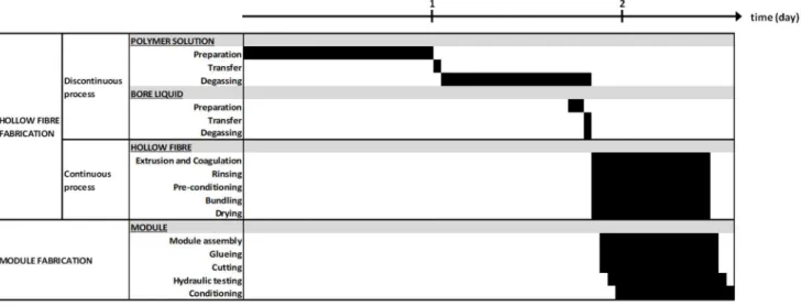
2.3.3 Industrial process
The industrial process can be divided into three stages: hollow fibre spinning, module preparation and module testing.
Figure I.3 is an example of the spinning process, which is typically highly automated. The polymer solution is stirred and heated in a vessel (2) until the polymer has completely dissolved and transferred to a degassing vessel (3). Gas bubbles from the polymer solution are removed, by a vacuum extraction system for example, to avoid the rupture of the skin layer and presence of holes across the final hollow fibre's thickness. The degassed polymer solution is filtered to remove any macro-waste or undissolved polymer and transferred to the spinneret (8) into the coagulation bath (9). A bore liquid is also prepared (6) and pumped to the spinneret. As detailed in the enlarged version of the spinneret, the bore liquid and polymer solution are pumped at a controlled flow rate in its centre-tube and outer-orifice respectively. This configuration offers adequate flexibility to choose the number and location of the hollow fibre's selective layers (inside and/or outside surface). Hollow fibres possess their final structure upon leaving the bath along the spinning chain. A rinsing step (10)
14
eliminates any remaining solvent in the membrane structure. The hollow fibre can be placed in a storage tank (12) or wound as a bundle on a mechanical arm for subsequent module preparation.
Figure I.3 Spinning process (adapted from Deshmukh & Li, 1998)
The module preparation process during which hollow fibres are assembled into modules is less documented in the literature than spinning and is primarily based on proprietary information and patents (Abidine, 1995; Espenan & Saux, 2017; Liou & Aptel, 1990; Saux & Wessel, 1993; Schutz & Paris, 1990). Li et al. (2004) are one of the few making the connection between lab-scale research and industrial-scale production. Stakes for module preparation are threefold:
- secure module integrity (waterproof sealing and resistance to chemicals, heat flow, mechanical and hydraulic stress) for a prolonged lifespan;
- guarantee a compact assembly of hollow fibres inside the membrane housing so as to limit the module's physical footprint during filtration operation;
- maintain good hydraulic profile inside the module, which could for example be jeopardized by dead zones created by fibres packed too close to one another.
Hollow fibres are first placed as bundles in a membrane housing and cut at the desired length. A potting compound (epoxy resin, polyurethane...) is injected on both ends to seal the module's inside volume. The adhesion of the potting compound to the membrane housing and hollow fibres' outer surface is crucial to maintain a waterproof seal even under pressure. Preliminary drying of hollow fibres is sometimes carried out for effective adhesion. In that case, a liquid chemical may first be added to lower surface tension of air-liquid interfaces inside pores and prevent them from collapsing during drying. This is especially true for membranes with small pore sizes for which the pressure difference across the air-water interface in the pores can be greater than yield strength. The added chemical may be evaporated (alcohol, acetone...) or remain in pores (glycerol or PEG in water, isopropanol...) during drying.
15
A final stage is to test the module against specifications (permeability, rejection, tensile force...). The intactness of hollow fibres in a module is furthermore checked by integrity testing. Pressure hold tests and bubble tests are two examples of such testing. In both tests air is applied to one of the fibres' side (intake or permeate side) at a pressure below the bubble point. During pressure hold tests valves are closed to isolate the module and pressure on the fibres' other side is measured. Pressure can slightly drop with air diffusing in the fluid inside the membrane pores. There is a leak if the pressure drops substantially. During bubble tests there is a leak if bubbles appear on the fibres' other side. Leaks can for example come from a defective fibre. Filling both fibre ends with potting compound condemns it.
2.4TOWARDS SUSTAINABLE UF MEMBRANES
2.4.1 Stakes and issues
Membrane fabrication has not been exempted from health, safety and environmental concerns. As regards NIPS processes, and phase inversion in general, focus in the literature is restricted to the two raw materials used in greatest quantities: the solvent and polymer that is initially dissolved.
Three of the most common dipolar aprotic solvents used for NIPS (N-methyl-2-pyrrolidone (NMP), N,N-dimethylacetamide (DMA) and N,N-dimethylformamide (DMF)) are identified by the European REACH regulation as substances of very high concern for their potential reproductive toxicity. Other adverse effects include flammability, eye irritation, respiratory irritation and skin sensitization. Their current use during membrane fabrication requires precautionary measures to be taken to reduce solvent exposure and protect workers' health and safety. Their future use is compromised since regulatory restrictions aim at substitution by less toxic alternatives.
The initial amount of solvent is entirely found in wastewater after membrane coagulation and rinsing. Razali et al. (2015) estimate that this wastewater represents more than 95% of the total waste produced during membrane fabrication. Their survey pinpointed that only 4 out of the 13 surveyed membrane manufacturing companies treat wastewater before disposal. It has however been calculated that solvent concentration in wastewater is always above the 100 ppm organic impurity threshold. In that respect, the challenge is to recover water of adequate quality (lower than 8 ppm of solvent) and at operating costs and energy requirements lower than by distillation (i.e. minimum 80 MJ m-2 membrane) for re-use during coagulation and rinsing (Razali et al., 2015).
The petrochemical origin of both common polymers and solvents used in membrane fabrication gives rise to environmental concerns that mirror those voiced on a global scale. Depletion of fossil resources, climate change due to greenhouse gas emissions and adverse health effects due to inhalation of volatile organic compounds are reasons put forth to reduce dependency on fossil-based resources. The petrochemical production of 1 kg of THF, for example, requires 271 MJ-eq, far above the 91 MJ-eq and 50 MJ-eq necessary to produce 1 kg of DMF and ethanol respectively. This is due to the complex production route needed (Capello et al., 2007).
16
2.4.2 Toxic solvent substitution
Medina-Gonzalez et al. (2011) were one of the first research teams to consider toxic solvent substitution in membrane fabrication. Their work is extensively referred to in Figoli et al.'s (2014) review on the beginning stages of solvent substitution in membrane fabrication in which examples are given of less or non-toxic solvents, seven of which apply specifically to NIPS processes. Since then, there have been a limited number of new examples of alternative solvents. Solubility parameters are often used to indicate whether a solvent can potentially dissolve the chosen polymer. Solubility must however always be observed experimentally. As for solvent toxicity, information can be found in institutional chemical databases or material safety data sheets.
One category of alternative solvents tackles the reprotoxicity issue without any shift of paradigm concerning the solvents’ fabrication process. This is the case of triethylphosphate derived from phosphate rock, a critical raw material as identified by the European Union (European Commission, 2017) and used to fabricate PVdF membranes (Abed et al, 2012). Rhodiasolv®Polarclean and Tamisolve®NxG are two industrial trademarks for petrochemical-based solvents investigated for NIPS (Dong et al., 2018; Marino et al., 2017; Marino et al., 2018; Wang et al., 2019). The former is a by-product of polyamide 6.6 synthesis and the latter (1-butylpyrrolidin-2-one) a compound structurally similar to NMP.
Bio-sourced solvents such as methyl lactate, an ester derived from lactic acid bacterial fermentation, have also been tested in the literature. Cellulose acetate (CA) flat membranes with either LiCl or CaCl2 as additives have been obtained and performances acceptable for UF (permeability up to 177 L
m-2 h-1 bar-1, molecular weight cut-off (MWCO) between 15 and 35 kDa with PEG as tracer, breaking
pressure equal to 3 bars or more) (Medina-Gonzalez et al., 2011). Further testing as regards mechanical properties or fouling behaviour is necessary to confirm its technical relevance, as well as the technical feasibility of hollow fibre fabrication. Dihydrolevoglucosenone is described as a promising alternative for common dipolar aprotic solvents (Marino et al., 2019). Its commercialisation phase as CyreneTM as trademark may lead to greater application in membrane
preparation.
Ionic liquids have recently emerged as alternatives (Kim et al., 2017; Xing et al., 2010). These salts have a melting point below 100°C and their properties, solubility in particular, can be tuned according to the nature of the cation or anion. Toxicity data is however still limited and certain ionic liquids have been flagged as toxic or flammable. The synthesis route from petrochemicals, reported to be material and energy consuming, offers further scope for improvement (Clark & Tavener, 2007).
2.4.3 Petrochemical polymer substitution
Galiano et al.'s (2018) review puts forth research efforts as regards the use of polymers derived from plant and animal sources, as well as from bacterial fermentation products for membrane fabrication applied to a variety of fields (water treatment, gas and liquid separation, medical applications).
17
Cellulose derivatives and polylactic acid (PLA) stand out as major bio-sourced polymers for UF. Whereas industrial applications exist for the former, research is still ongoing for the latter.
CA has been used for drinking water treatment by UF since the 1980s (Bersillon et al., 1989; Cabassud et al., 1991). This polymer synthetized by the acetylation of cellulose, obtained from wood pulp or cotton, shows interesting hydrophilic features for water treatment. CA is usually used as sole component of UF membranes (Medina-Gonzalez et al., 2011; Nakatsuka et al., 1996; Qin et al., 2003; Saljoughi & Mohammadi, 2009). Blends have been investigated to either improve performances or mitigate limitations of basic membranes. Kanagaraj et al. (2016) used macromolecules prepared from polyurethane pre-polymers to modify CA membrane surfaces. Macromolecules incorporated in the polymer solution before dry/wet phase separation led to membranes with greater surface hydrophilicity compared to non-blended membranes. Deposition and adsorption of humic acids during UF tests were reduced. Sivakumar et al. (2006) used CA to decrease the hydrophobicity of polysulfone membranes and applied the resulting blended membranes to protein and heavy metal ion separation.
More recently, Hanafia et al. (2017) casted membranes from hydroxypropylcellulose, a thermo-responsive cellulose ether. Besides a pore-forming additive, a cross-linking agent and cross-linking reaction catalyst were added to the polymer solution. Cross-linking was necessary to obtain an isotropic structure and prevent the final membrane from dissolving in water. A variant of the classic TIPS process was applied; temperature was increased above its lower critical solution temperature to induce phase separation.
Several examples of PLA membranes fabricated by phase inversion can be found in the literature (Chinyerenwa et al., 2018; Chitrattha & Phaechamud, 2013; Moriya et al., 2009; Moriya et al., 2012; Phaechamud & Chitrattha, 2016). The polymer is obtained either from ring-opening polymerization of lactide (i.e. cyclic di-ester derived from lactic acid) or via direct polycondensation of lactic acid. Its biodegrability and biocompatibility explain the preferential use for medical and pharmaceutical applications. PLA use in water treatment by membrane separation has been carried out by Moriya et al. (2009, 2012). One limitation concerned the hydrolytic decomposition of the polymer: model protein rejection of the fabricated PLA membranes dropped from 80.0 to 31.5% after having been kept 10 months in water at room temperature. A second limitation linked to the adsorption of model proteins and natural organic matter was mitigated by inserting up to 5 wt% of triblock co-polymer (i.e. PLA−PEG−PLA) in the polymer solution. Relative permeabilities of blended membranes achieved 0.9 for separate filtration of bovine serum albumin and humic acid, an improvement compared to 0.3 and 0.7, respectively, obtained with non-blended membranes.
2.4.4 Conclusion
Research efforts towards sustainable UF membranes are focused on substituting toxic solvents and petrochemical-based polymers. As noted by Jiang and Ladewig (2019), these efforts render
18
membrane preparation only partially eco-friendly since not all inputs, from raw material fabrication to possible membrane post-treatment, are considered. Furthermore, such substitutions are done empirically with solubility parameters as sole methodological approach. Technical feasibility of membrane fabrication with these substitutes is shown but comparative environmental assessment between original and alternative processes is absent from the literature.
19
3 UF PROCESS IN DRINKING WATER TREATMENT
3.1UF TECHNOLOGY IN A WATER TREATMENT PROCESS
3.1.1 UF as unit operation
Given the physical barrier it represents for colloidal matter and pathogenic impurities, UF can be used in drinking water treatment for both clarification and disinfection purposes. Common examples of membrane integration are given in Figure I.4. Basic pre-treatment and UF typically suffice for low-concentration turbid water (0-1 NTU) with low levels of organic matter (0-1 mg TOC L-1). For higher
loads, UF can substitute sand filtration and disinfection operations in a more qualitative manner. UF may also be used downstream of conventional clarification (coagulation-flocculation-settlement and sand filtration) to secure water quality.
Figure I.4 UF integration in drinking water treatment
In integration levels 2 and 3, powder activated carbon (PAC) may be injected upstream, for pesticide adsorption for example and be removed by membrane separation. This avoids using GAC filtration columns. Even after a chemical-free disinfection by UF, post-disinfection remains necessary to maintain a residual disinfectant concentration through the distribution system to the point of use.
Just as raw water quality impacts on the designed water treatment process, the quality of UF input water can impact on its mode of operation (i.e. dead-end or cross-flow). Dead-end operation, for which all input water passes through the membrane layer, has the advantage of consuming approximately 0.3 kWh m-3 less energy compared to a cross-flow operation and is therefore
industrially preferred (Glucina et al., 1998). The latter mode of operation may be used to treat occasional turbid input water, notably for PAC concentrations above 5 ppm.
In what follows, only dead-end operation is considered. The absence of recirculation pumping system leads to more compact module configurations.
3.1.2 Module configuration