Science Arts & Métiers (SAM)
is an open access repository that collects the work of Arts et Métiers Institute of
Technology researchers and makes it freely available over the web where possible.
This is an author-deposited version published in: https://sam.ensam.eu Handle ID: .http://hdl.handle.net/10985/13799
To cite this version :
Mario BERMUDEZ GUZMAN, Ignacio GONZALEZ PRIETO, Federico BARRERO, Hugo GUZMAN, Mario Javier DURAN, Xavier KESTELYN - Open-Phase Fault-Tolerant Direct Torque Control Technique for Five-Phase Induction Motor Drives - IEEE Transactions on Industrial Electronics - Vol. 64, n°2, p.902 - 911 - 2017
Any correspondence concerning this service should be sent to the repository Administrator : archiveouverte@ensam.eu
Science Arts & Métiers (SAM)
is an open access repository that collects the work of Arts et Métiers ParisTech
researchers and makes it freely available over the web where possible.
This is an author-deposited version published in: https://sam.ensam.eu Handle ID: .http://hdl.handle.net/null
To cite this version :
Mario BERMUDEZ GUZMAN, Ignacio GONZALEZ PRIETO, Federico BARRERO, Hugo GUZMAN, Mario Javier DURAN, Xavier KESTELYN - Open-Phase Fault-Tolerant Direct Torque Control Technique for Five-Phase Induction Motor Drives - IEEE Transactions on Industrial Electronics - Vol. 64, n°2, p.902 - 911 - 2017
Any correspondence concerning this service should be sent to the repository Administrator : archiveouverte@ensam.eu
Abstract—Direct torque control (DTC) has been widely used as
an alternative to traditional field-oriented control (FOC) methods for three-phase drives. The conventional DTC scheme has been successfully extended to multiphase drives in recent times, using hysteresis regulators to independently track the desired torque and flux in symmetrical five-phase induction machines (IM). The fault-tolerant capability of multiphase drives is an interesting intrinsic advantage for safety-critical applications, where recent research has demonstrated the effectiveness of FOC schemes to perform ripple-free post-fault operation. In spite of the utility of DTC methods in normal operation of the multiphase machine, no extension to manage the post-fault operation of the drive is found in the literature. In this paper, a novel fault-tolerant DTC scheme is presented. The performance of the proposed method is experimentally validated in a five-phase IM drive considering an open-phase fault condition. Provided tests analyze steady and transient states, including the transition from pre- to post-fault operation. Obtained results prove the interest of the proposal, which ensures the open-phase fault-tolerant capability of DTC controlled five-phase IM drives.
Index Terms—Direct torque control (DTC), fault-tolerant
capability, multiphase induction motor (IM) drives, open-phase fault operation.
I. INTRODUCTION
ULTIPHASE drives have gained special relevance in modern times for their use in applications where high overall system reliability and reduction in the total power per phase are required, such as in electric vehicles and trains, all-electric ships, more-all-electric aircrafts or wind power generation systems [1–3]. Conducted research has recently focused on the
M. Bermudez is with the Laboratory of Electrical Engineering and Power Electronics of Lille (L2EP), Arts et Métiers ParisTech, 59046 Lille Cedex, France, and also with the Department of Electronic Engineering, University of Seville, 41004 Seville, Spain (e-mail: mario.bermudez-guzman@ensam.eu).
I. Gonzalez-Prieto and M. J. Duran are with the Department of Electrical Engineering, University of Málaga, 29071 Málaga, Spain (e-mail: igp@uma.es; mjduran@uma.es).
F. Barrero is with the Department of Electronic Engineering, University of Seville, 41004 Seville, Spain (e-mail: fbarrero@us.es).
H. Guzman is with the Department of Electronic and Electrical Engineering, University of Sheffield, S1 4DE Sheffield, United Kingdom (e-mail: h.g.jimenez@sheffield.ac.uk).
X. Kestelyn is with the Laboratory of Electrical Engineering and Power Electronics of Lille (L2EP), Arts et Métiers ParisTech, 59046 Lille Cedex, France (e-mail: xavier.kestelyn@ensam.eu).
design of multiphase machines and the effect of the stator winding connection [4,5], on the consideration of power converters’ topologies [6] and on new control schemes to exploit the additional degrees of freedom [7].
An extended case example of multiphase drives is the symmetrical five-phase induction machine with sinusoidally distributed stator windings. Regarding the existing control techniques, the Rotor-Field Oriented Control (RFOC) method, based on an outer PI-based speed control loop and inner current controllers, is the most widespread control technique in the multiphase case. This technique has been applied in five-phase IM drives using conventional PI-based current regulators or model-based predictive current controllers in healthy [8,9] and faulty operation [10–12]. Other well-known non-linear controller like DTC, a leading technology for three-phase induction motor drives since 1995 [13], has not been so deeply extended to the multiphase case, where only healthy operation of five-phase IM drives is considered [14,15]. The use of DTC in five-phase IM is limited due to the impossibility of regulating more than two degrees of freedom (electrical torque and stator flux), which are regulated using hysteresis controllers and switching tables that impose the stator voltage of the five-phase IM. The proposed schemes successfully perform in healthy state, including the low-speed operation, using additional virtual voltage vectors and diminishing non-torque stator current components.
Improving the fault-tolerant capability is a hot topic in five-phase induction motor drives [4,5,10–12,16,17]. However, this fault-tolerant capability using DTC methods has not been stated yet, being this a main contribution of our work. Notice that the number of degrees of freedom reduces when faulty situations appear and the inconvenient of using the DTC method is expected to be mitigated, something that has not been verified yet. Although different types of faults can occur, the most considered is the open-phase one that leads to a reduction in the number of active phases in the multiphase drive [3]. Important requirements must be introduced to take into account the open-phase fault occurrence [10–12]. For example, stator current references must be modified to preserve the fundamental component of the air gap magnetic field, where different post-fault control criteria (e.g. reduce copper losses or ensure maximum torque capability [16–18]) can be applied. If inner current control loops are implemented using linear controllers, the oscillating nature of the current references makes imperative the use of proportional resonant (PR) regulators in the post-fault
Open-Phase Fault-Tolerant Direct Torque Control
Technique for Five-Phase Induction Motor Drives
Mario Bermudez, Ignacio Gonzalez-Prieto, Federico Barrero, Senior Member, IEEE, Hugo Guzman,
Mario J. Duran, and Xavier Kestelyn, Member, IEEE
operation of the drive, being this the main reason of a change in the control scheme between pre- and post-fault operation. If a model-based predictive current control scheme is used, the model of the electrical drive under the faulty condition must be considered and the applied cost function must change.
This work extends the DTC method used in normal operation of five-phase IM drives to the open-phase fault procedure. The proposed DTC technique, initially presented in [19] but experimentally validated here, requires i) the modification of classic DTC structures using a reduced-order transformation matrix, ii) the redefinition of the utilized virtual voltage vectors by means of the available voltage vectors in faulty operation, and iii) the elaboration of a new look-up table for the control purpose. The paper is organized as follows. Section II analyzes the five-phase IM drive under healthy and faulty operations, showing the effect of the open-phase fault occurrence in the physical system. The proposed fault-tolerant DTC scheme is detailed in Section III. Section IV provides experimental results to show and discuss the performance of the multiphase drive using the proposed post-fault controller. Finally, the conclusions are presented in the last section.
II. FIVE-PHASE IM DRIVE IN NORMAL AND OPEN-PHASE FAULT OPERATION
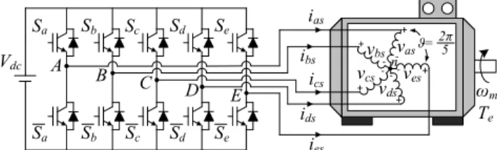
The system under study is based on a five-phase IM with a squirrel-cage rotor and symmetrically distributed stator windings (with a fixed spatial displacement of ϑ=2π/5 between windings). A simplified scheme of the drive is shown in Fig. 1, where the machine is powered by a two-level five-phase voltage source inverter (VSI). If the switching state of each power converter leg is called Si, where i={a, b, c, d, e} and Si=0 if the
lower switch is ON and the upper switch is OFF or Si=1 if the
opposite occurs, then the vector [Sa Sb Sc Sd Se]T identifies the
25=32 available switching states and stator voltages. Each stator phase voltage can be obtained from this vector and the DC-link voltage (Vdc) as it is stated in (1) and, applying the
current-invariant decoupling Clarke’s transformation defined in (2), can be mapped into two orthogonal stationary subspaces, α-β and x-y, plus a zero-sequence component (see Fig. 2, where stator
voltage vectors have been identified using a decimal number equivalent to the binary number [Sa Sb Sc Sd Se]).
− − − − − − − − − − − − − − − − − − − − = e d c b a dc es ds cs bs as S S S S S V v v v v v · 4 1 1 1 1 1 4 1 1 1 1 1 4 1 1 1 1 1 4 1 1 1 1 1 4 5 (1) = es ds cs bs as zs ys xs s s v v v v v v v v v v · 2 / 1 2 / 1 2 / 1 2 / 1 2 / 1 3 sin sin 4 sin 2 sin 0 3 cos cos 4 cos 2 cos 1 4 sin 3 sin 2 sin sin 0 4 cos 3 cos 2 cos cos 1 5 2 ϑ ϑ ϑ ϑ ϑ ϑ ϑ ϑ ϑ ϑ ϑ ϑ ϑ ϑ ϑ ϑ β α (2) Vdc ias + -vbs vas + -+ vcs -ves -+ -vds + Sb Sc Sd Se Sa n A B C D E Sa Sb Sc Sd Se ibs ics ies ids ϑ=2π5 ωm Te Fig. 1. Schematic diagram of the five-phase IM drive.
-1 -0.5 0 0.5 1 -1 -0.8 -0.6 -0.4 -0.2 0 0.2 0.4 0.6 0.8 1 31 1 2 3 4 5 6 7 8 9 10 11 12 14 15 16 17 18 19 20 21 22 23 24 25 26 27 28 29 30 α–β 0 β b c d e α a 13 -1 -0.5 0 0.5 1 -1 -0.8 -0.6 -0.4 -0.2 0 0.2 0.4 0.6 0.8 1 31 1 8 12 2 6 3 7 15 16 20 17 21 24 28 25 22 19 23 27 0 y b c d e x a 14 x–y 4 5 9 13 10 11 29 18 26 30
Fig. 2. Available voltage vectors in the α–β (left plot) and x–y (right plot) planes in normal operation.
The five-phase IM can be modeled in a stationary reference frame with a set of voltage equilibrium equations obtained from the stator and rotor electromagnetic circuits. All the standard assumptions normally applied in three-phase IM are considered, including sinusoidal spatial MMF distribution, uniform air gap and some neglected effects like magnetic saturation, core losses and mutual leakage inductance between windings of different phases. Taking this into account, the following set of equations describes the behavior of the multiphase machine:
]) [ )] ( ([ ] [ ]· [ ] [ ] [ ] [ ] [ ] [ ] [ r sr s ss s s s s s s I L dt d I dt d L I R dt d I R V ⋅ + + ⋅ = + ⋅ = θ λ (3) ]) [ )] ( ([ ] [ ]· [ ] [ ] [ ] [ ] [ ] [ ] [ s rs r rr r r r r r r I L dt d I dt d L I R dt d I R V ⋅ + + ⋅ = + ⋅ = θ λ (4)
[ ]
5 · ] [Rs =Rs I (5)[ ]
5 · ] [Rr =Rr I (6)[ ]
·[
( )]
· ] [Lss =Lls I5 +M Λϑ (7)[ ]
·[
( )]
· ] [Lrr =Llr I5 +M Λϑ (8)[
( )]
·[ ]
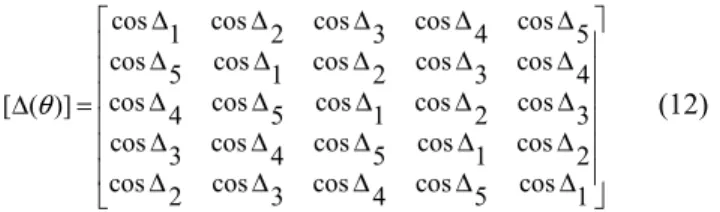
( ) )] ( [L θ = L θ T =M ∆θ rs sr (9)∫
= t rdt 0 ω θ (10) = Λ 1 4 cos 3 cos 2 cos cos cos 1 4 cos 3 cos 2 cos 2 cos cos 1 4 cos 3 cos 3 cos 2 cos cos 1 4 cos 4 cos 3 cos 2 cos cos 1 )] ( [ ϑ ϑ ϑ ϑ ϑ ϑ ϑ ϑ ϑ ϑ ϑ ϑ ϑ ϑ ϑ ϑ ϑ ϑ ϑ ϑ ϑ (11) ∆ ∆ ∆ ∆ ∆ ∆ ∆ ∆ ∆ ∆ ∆ ∆ ∆ ∆ ∆ ∆ ∆ ∆ ∆ ∆ ∆ ∆ ∆ ∆ ∆ = ∆ 1 cos 5 cos 4 cos 3 cos 2 cos 2 cos 1 cos 5 cos 4 cos 3 cos 3 cos 2 cos 1 cos 5 cos 4 cos 4 cos 3 cos 2 cos 1 cos 5 cos 5 cos 4 cos 3 cos 2 cos 1 cos )] ( [ θ (12)
where V, I and λ denote voltage, current and flux variables, and the s and r subscripts identify the stator and rotor variables, respectively. The electrical parameters of the machine are Rs
and Rr (stator and rotor resistances), M (mutual inductance), and
Lls and Llr (stator and rotor leakage inductances), while [I5]
represents an identity matrix of order 5 and the angles ∆k are
defined as ∆k=θ+(k−1)ϑ, where k={1,2,3,4,5} and θ is the
instantaneous rotor azimuth with respect to the α-axis, obtained through the rotor electrical speed (ωr).
The equilibrium equation (13) is verified during the normal operation of the multiphase drive. However, the machine becomes asymmetrical when an open-phase fault occurs and the sum of healthy stator phase voltages is no longer zero. Since the five-phase machine is symmetrical, the analysis when the fault appears can consider any faulty phase without lack of generality. Then, phase ‘a’ will be considered like the faulty phase from now on, being ias=0. In any case, one degree of
freedom is lost in the multiphase drive when the fault appears, and a fixed relationship between α and x current components is obtained as it is stated in (14). It is then necessary to include the induced back-EMF of the phase ‘a’ in the new equilibrium stator phase voltage equation (15), which is obtained from (1) with Lm=5M/2. es ds cs bs as v v v v v + + + + = 0 (13) xs s xs s as i i i i i =0= α + ⇒ α =− (14) + − − − − − − − − − − − − − = 1 1 1 1 4 · 3 1 1 1 1 3 1 1 1 1 3 1 1 1 1 3 4 dt di dt di L S S S S V v v v v s r m e d c b dc es ds cs bs α α (15)
Equation (15) links switching states and stator phase voltages of healthy phases, being the back-EMF of phase ‘a’ (obtained from the neutral voltage evaluation, [10]) the second term on the right hand side. This back-EMF term can be neglected, as it is shown in [11], and will not be considered in what follows for the sake of simplicity. The modified Clarke’s transformation presented in [10] and shown in (16) can be used in the post-fault operation to compensate asymmetries of the machine. Then, a symmetrical post-fault model of the machine is obtained, as well as circular trajectories of the stator currents in the α-β plane,
and the same set of equations in α-β-x-y coordinates is
generated in normal and post-fault conditions. Consequently, the samemodel of the drive under healthy and fault conditions is used, which simplifies the treatment of the fault. However, the open-phase fault situation is characterized by four healthy phases, and the number of switching states is reduced from 25=32 to 24=16, as it is shown in Fig. 3. 0 15 1 2 3 4 5 6 7 8 9 10 11 12 13 14 β α– -1 -0.5 0 0.5 1 -1 -0.8 -0.6 -0.4 -0.2 0 0.2 0.4 0.6 0.8 1 β α a b e d c 0 15 4 1 5 8 12 9 13 2 6 3 7 10 14 11 -1 -0.5 0 0.5 1 -1 -0.8 -0.6 -0.4 -0.2 0 0.2 0.4 0.6 0.8 1 y x a b e d c x–y
Fig. 3. Available voltage vectors in the α–β (left plot) and x–y (right plot) planes in open-phase fault operation.
− − − − = es ds cs bs zs ys s s v v v v v v v v · 1 1 1 1 8 sin 6 sin 4 sin 2 sin 4 sin 3 sin 2 sin sin 1 4 cos 1 3 cos 1 2 cos 1 cos 5 2 ϑ ϑ ϑ ϑ ϑ ϑ ϑ ϑ ϑ ϑ ϑ ϑ β α (16)
III. DTC SCHEME IN OPEN-PHASE OPERATION
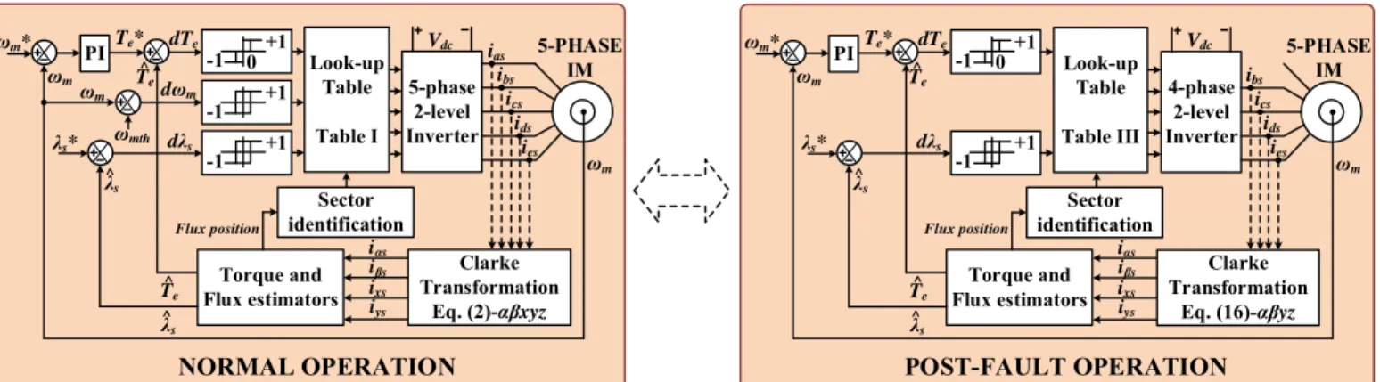
Traditional DTC methods have been successfully extended to five-phase drives, where some advances have been recently achieved in the application of switching table DTC techniques at healthy operation of the drive [14,15]. The main control criterion is to maximize torque production while minimizing overall losses, and a stator voltage vector is therefore applied every sampling period for reference torque and stator flux tracking. The controller (see left plot in Fig. 4) is based on a three-level torque hysteresis comparator and two two-level hysteresis-based control loops for regulating the flux, where the low-speed operation of the drive is also taken into account and the effect of neglecting the stator resistance is considered with a speed threshold called ωmth (100 rpm in our case). In healthy
operation, ten different sectors appear in α-β and x-y planes,
with a small, a medium and a large voltage vector in every sector (notice in Fig. 2 that a large vector in the α-β plane results in a
small vector in the x-y plane and vice versa). However, these
available stator voltage vectors are not applied, and Virtual Voltage Vectors (VVi from now on) are created to reduce
harmonic components in the x-y plane, which do not produce
torque in a distributed winding multiphase IM. Thus, a null voltage vector (V0 or V31) or VVi is applied to the five-phase IM
during a sampling period Ts, being VVi obtained with one large
and one medium voltage vector that must be in-phase in the α
-β plane to generate a zero average voltage vector in the x-y
plane. As a result, the synthesized VVi, shown in Fig. 5(a), has a
magnitude of ((5–√5)/5)·Vdc with normalized dwell times of Kv
=(3–√5)/2 and 1–Kv referred to Ts. Electrical torque and flux
estimators are used to calculate the hysteresis regulators error signals and identify the sector on the basis of the stator flux position, and the applied voltage vector (VVi with i=1 to 10 or
the null voltage vectors V0 and V31) is obtained from the
look-up table shown in Table I.
Some modifications must be applied when an open-phase fault occurs in order to ensure the post-fault operation of the multiphase drive. The overall aim must be the extension of the control technique to the post-fault situation, where the open-
4-phase 2-level Inverter λs* ωm ibs ics ids ies Vdc ωm PITe* dTe dλs Torque and Flux estimators ωm* +1 -1 0 +1 -1 Flux position λs ^ 5-PHASE IM POST-FAULT OPERATION Clarke Transformation Eq. (16)-αβyz iαs ixs iβs iys T^e λs ^ T^e 5-phase 2-level Inverter λs* ωm ibs ics ids ies Vdc ωm PI Sector identification Te* dTe dλs Look-up Table Table I Torque and Flux estimators ωm* +1 -1 0 +1 -1 Flux position λs ^ 5-PHASE IM NORMAL OPERATION Clarke Transformation Eq. (2)-αβxyz iαs ixs iβs iys T^e λs ^ T^e ωmth ωm dωm +1 -1 ias Sector identification Look-up Table Table III
Fig. 4. Proposed fault-tolerant DTC technique in symmetrical five-phase IM drives. The method applied during the healthy or normal operation of the drive (left side) must be modified during open-phase post fault operation (right side). The symbols ‘^’ and ‘*’ represent estimated and reference variables, respectively. The electrical drive is operated below rated speed, and the stator flux reference (λs*) is mantained constant and equal to its nominal value. The stator flux and the
electrical torque are estimated using observers detailed in [14,15].
TABLEI
LOOK-UP TABLE FOR THE DTC CONTROLLER IN HEALTHY OPERATION
dλs dTe dωm Position of stator flux (Sector)
1 2 3 4 5 6 7 8 9 10 +1 +1 +1 VV3 VV4 VV5 VV6 VV7 VV8 VV9 VV10 VV1 VV2 -1 VV2 VV3 VV4 VV5 VV6 VV7 VV8 VV9 VV10 VV1 -1 +1 VV9 VV10 VV1 VV2 VV3 VV4 VV5 VV6 VV7 VV8 -1 VV10 VV1 VV2 VV3 VV4 VV5 VV6 VV7 VV8 VV9 0 +1 V0 V31 V0 V31 V0 V31 V0 V31 V0 V31 -1 V0 V31 V0 V31 V0 V31 V0 V31 V0 V31 -1 +1 +1 VV4 VV5 VV6 VV7 VV8 VV9 VV10 VV1 VV2 VV3 -1 VV5 VV6 VV7 VV8 VV9 VV10 VV1 VV2 VV3 VV4 -1 +1 VV8 VV9 VV10 VV1 VV2 VV3 VV4 VV5 VV6 VV7 -1 VV7 VV8 VV9 VV10 VV1 VV2 VV3 VV4 VV5 VV6 0 +1 V31 V0 V31 V0 V31 V0 V31 V0 V31 V0 -1 V31 V0 V31 V0 V31 V0 V31 V0 V31 V0 VV1(9) VV2(13,8) VV8(11,1) VV7(5,3) VV4(4,14) V0, V15 VV5(6) VV6(2,7) VV3(10,12) α β 2 3 4 5 6 7 8 1 V0, V31 α β 2 3 4 5 6 7 8 1 9 10 VV1(16,25) VV2(29,24) VV3(8,28) VV4(30,12) VV5(4,14) VV6(15,6) VV7(2,7) VV8(23,3) VV9(1,19) VV10(27,17) (a) (b)
Fig. 5. Virtual voltage vectors (VVi) in the α–β subspace during (a) normal
and (b) open-phase post-fault operation.
phase fault reduces the number of controllable variables (only α, β and y current components, while x current component is found to be ixs=-iαs), being α-β and x-y subspaces no longer
orthogonal. In this case, the proposed open-phase fault DTC scheme reduces copper losses in the faulty operation and is designed with the following considerations:
• New VVi values are obtained to take into account that there
are only 16 available voltage vectors in post-fault operation, as it is illustrated in Fig. 3.
• The additional freedom degree (y component) is used to obtain zero average volts-per-seconds in the y direction during the post-fault operation of the drive. This should be equivalent to the minimum copper loss criterion assuming that machine asymmetries do not exist, because the stator
current component in the y axis (iys) will be low and close
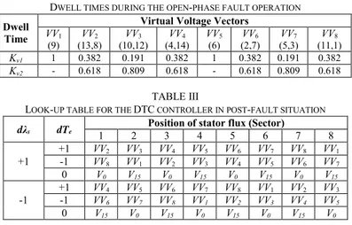
to zero [16–18]. The existence of some degree of asymmetry is then regarded as a non-modelled effect that may cause some disturbance in the current regulation. Eight sectors appear in the open-phase fault situation, which leads to eight VVi in the α-β plane defined as:
2 2 1 1 2 1, ) ( v v i v v vK v K VV = + (17)
where v1 and v2 are the two available voltage vectors and Kv1 and
Kv2 are the dwell time ratios that define VVi with the condition
iys=0. Sectors 1 and 5 are exceptions and only use one vector
since it does not produce voltage in the y direction. The obtained post-fault VVi and sectors are depicted in Fig. 5b, and the new
obtained dwell time ratios are shown in Table II. The look-up table that takes into account the open-phase fault situation is detailed in Table III, where the applied stator voltage vector is the null voltage vector (V0 or V15) or VVi, with i=1 to 8.
The post-fault DTC technique is detailed in Fig. 4 (see right plot). The controller includes an outer PI-based speed control loop and two inner torque and flux hysteresis regulators (dλs and
dTe error signals). Notice that the low speed region cannot be
considered like in healthy case, because of the defined sectors and VVi values. Finally, electrical torque and flux estimators are
used to identify the sector on the basis of the stator flux position to obtain the applied voltage vector (see Table III). Notice that the estimators use the same equations under healthy and faulty
TABLE II
DWELL TIMES DURING THE OPEN-PHASE FAULT OPERATION
Dwell Time
Virtual Voltage Vectors
VV1
(9) (13,8) VV2 (10,12) VV3 (4,14) VV4 VV(6) 5 (2,7) VV6 (5,3) VV7 (11,1) VV8
Kv1 1 0.382 0.191 0.382 1 0.382 0.191 0.382 Kv2 - 0.618 0.809 0.618 - 0.618 0.809 0.618
TABLE III
LOOK-UP TABLE FOR THE DTC CONTROLLER IN POST-FAULT SITUATION dλs dTe 1 2 Position of stator flux (Sector) 3 4 5 6 7 8
+1 +1 -1 VVVV82 VV VV13 VV VV42 VV VV53 VV VV46 VV VV57 VV VV68 VV VV17
0 V0 V15 V0 V15 V0 V15 V0 V15
-1 +1 -1 VVVV64 VV VV75 VV VV68 VV VV71 VV VV28 VV VV31 VV VV42 VV VV35
0 V15 V0 V15 V0 V15 V0 V15 V0
conditions. However, one stator phase current is null in the open-phase fault condition and the modified Clarke’s transformation detailed in [10] is applied, see Eq. (16).
IV. EXPERIMENTAL RESULTS
To prove the viability and assess the performance of the proposed fault-tolerant control scheme, different experimental tests have been performed on a three-phase IM rewound to have five phases with 30-slots and three pairs of poles. The electrical machine is driven by two conventional three-phase VSIs from Semikron (two SKS-22F modules where five over six power legs are used). The DC-link voltage is set to 300 V during all the experimental tests using an external DC power supply. The electronic control unit is based on a MSK28335 board and a Texas Instruments TMS320F28335 DSP. A digital encoder (GHM510296R/2500) and the enhanced quadrature encoder pulse (eQEP) peripheral of the DSP are used to measure the rotor mechanical speed ωm. The load torque (TL), which is
demanded in the tests, is set by an independently controlled DC machine that is mechanically coupled to the five-phase machine.
The performed tests consider that the open-phase fault condition occurs in phase ‘a’ and the fault occurrence is emulated by opening a power relay connected in series with the faulty phase. The experimental test rig is shown in Fig. 6, where some photographs of the system are included. The electrical parameters of the five-phase IM were determined using AC-time domain and standstill control tests [20,21] (Table IV summarizes the electrical and mechanical specifications of the used five-phase IM). It is important to mention that during the following experimental tests the stator flux reference (λs*) was
set to 0.389 Wb, the applied sampling frequency was 10 kHz and the hysteresis bands of the torque and flux regulators were programmed to be at 1.06% and 1.29% of the rated values, respectively.
The behavior of the proposed DTC controller during the faulty open-phase operation of the drive is first analyzed assuming a null load torque condition and forcing a step in the speed reference from 0 to 500 rpm that is applied at t=0.1 s. Fig. 7 shows the obtained results: the mechanical speed (upper plot), estimated electrical torque (middle figure) and stator flux (lower
a b c d e RS232 Serial Ports 5-PHASE IM DRIVE Current Sensors DC MOTOR
DRIVE DC MOTOR 5-PHASE IM
CONTROL BOARD POWER ELECTRONIC CONVERTERS (VSIs) Switching Signals Phase Currents a b DC-LINK Vdc Speed Encoder (ωm)
Fig. 6. Graphical scheme of the multiphase experimental test rig based on a symmetrical five-phase distributed-windings IM.
(a) (b) (c) 0 0.5 1 1.5 2 2.5 3 0 200 400 600 Time (s) Sp ee d (r pm ) ωm ω*m 0 0.5 1 1.5 2 2.5 3 -2 0 2 4 6 Time (s) To rq ue (N ·m ) Te Te* -1 -0.5 0 0.5 1 -1 -0.5 0 0.5 1 λ λsβ (W b) λ^αs (Wb) ^ ^
Fig. 7. Step speed response test. The reference speed is changed from 0 to 500 rpm at t=0.1 s. No load torque condition is assumed. The upper plot shows the speed response (a), while the estimated electrical torque and the stator flux in the α–β plane is depicted in plots (b) and (c), respectively. Notice that the stator flux is evaluated from the measured stator currents and the estimated stator voltages (the estimation uses the switching state of the VSI).
TABLEIV
ELECTRICAL AND MECHANICAL PARAMETERS OF THE FIVE-PHASE IM
Parameter Value Unit
Stator resistance, Rs 12.85 Ω
Rotor resistance, Rr 4.80 Ω
Stator leakage inductance, Lls 79.93 mH
Rotor leakage inductance, Llr 79.93 mH
Mutual inductance, M 681.7 mH
Moment of inertia, J 0.02 kg-m2
Number of pole pairs, p 3 -
Rated torque, Tn 4.70 N-m
Rated stator flux, λs* 0.389 Wb
-2 -1 0 1 2 -2 -1 0 1 2 ixs (A) iys (A ) -2 -1 0 1 2 -2 -1 0 1 2 isβ (A ) -2 -1 0 1 2 -2 -1 0 1 2 ixs (A) iys (A ) -2 -1 0 1 2 -2 -1 0 1 2 isβ (A ) 0 0.5 1 1.5 2 2.5 3 400 450 500 550 600 Time (s) Sp ee d (r pm ) ωm ω*m (a) (b) (c) (d) TL = 0 TL = 0 TL = 0.50·Tn TL = 0 TL = 0.50·Tn 0 0.5 1 1.5 2 2.5 3 -1 0 1 2 3 4 5 Time (s) To rq ue (N ·m ) T^e Te* TL = 0.50·Tn i s(A) i s(A)
Fig. 8. Load torque rejection test where a change from 0 to 50% of the nominal load torque is applied at t=1.1 s. (a) Speed response. (b) Estimated electrical torque behavior. Stator current performance in α–β and x–y planes in steady state with (c) null and (d) 50% of the nominal torque, respectively.
illustration) behaviors. It can be observed that the proposed post-fault DTC scheme provides an accurate tracking of the reference speed and electrical torque. The performance of the estimated stator flux is also shown in Fig. 7(c), where a circle is obtained in the α–β plane polar diagram and the estimated stator
flux vector has a controlled behavior in order to drive the multiphase system.
The rejection properties of the proposed DTC scheme are also analyzed when a change in the load torque is applied. The obtained results are summarized in Fig. 8, where the demanded load torque is changed while the reference speed is kept constant at 500 rpm. The DC machine is initially programmed to apply a zero load torque in opposition to the multiphase drive’s electrical torque. Then, the load torque is forced to become about half of the nominal one (TL=0.5·Tn) at t=1.1 s. It is
observed a slight drop in the speed, although the controller successfully manages the disturbance, Fig. 8(a). The estimated electrical torque is also regulated to be the referred one in steady and transient states, as it is shown in Fig. 8(b), while stator currents in the α–β plane produce a circular trajectory in steady
state with TL=0 and TL=0.5·Tn conditions, as it is illustrated in
(a) (b) (c) 0 0.5 1 1.5 2 2.5 3 -4 -2 0 2 Time (s) To rq ue (N ·m ) Te Te * ^ 0.3 0.4 0.5 0.6 0.7 0.8 0.9 -4 -2 0 2 4 Time (s) Cu rr en t ( A ) iαs iβs iαs 0 0.5 1 1.5 2 2.5 3 -500 -250 0 250 500 Time (s) Sp ee d (r pm ) ωm ω*m
Fig. 9. Speed reversal test. The reference speed is changed from 500 to –500 rpm at 0.2 s. Speed and torque reference tracking are shown in (a) and (b) plots, respectively, while stator currents in the α–β plane is ploted at the zero-speed crossing point in (c).
(a) (b) 400 450 500 550 600 ωm ω*m ωm ω* m Fault Occurrence Time (s) 0 0.2 0.4 0.6 0.8 1 1.2 400 450 500 550 600 Sp ee d (rp m ) TL = 0.28·Tn (c) 0 0.2 0.4 0.6 0.8 1 1.2 ωm ω*m TL = 0.56·Tn ωm ω* m Fault Occurrence 400 450 500 550 600 Sp ee d (rp m ) Time (s) 0 0.2 0.4 0.6 0.8 1 1.2 ωm ω* m ωm ω* m Fault Occurrence TL = 0.70·Tn Time (s) 0 0.2 0.4 0.6 0.8 1 1.2 400 450 500 550 600 Sp ee d (rp m ) Te Te* TL = 0.28·Tn Fault Occurrence Te Te* Time (s) 0 0.2 0.4 0.6 0.8 1 1.2 -1 0 1 2 3 4 5 To rq ue (N ·m ) ^ Te Te* Time (s) 0 0.2 0.4 0.6 0.8 1 1.2 Te Te* TL = 0.56·Tn Fault Occurrence -1 0 1 2 3 4 5 To rq ue (N ·m ) ^ 0 0.2 0.4 0.6 0.8 1 1.2 Te Te* TL = 0.70·Tn Te Te* Fault Occurrence Time (s) 0 0.2 0.4 0.6 0.8 1 1.2 -1 0 1 2 3 4 5 To rq ue (N ·m ) ^
Fig. 10. Transition from pre- to post-fault open-phase operation using the proposed DTC controller and assuming instantaneous control reconfiguration when the fault appears at t=0.2 s. A reference speed of 500 rpm is assumed with an applied load torque of (a) 28%, (b) 56% and (c) 70% of the nominal one. The speed and estimated torque response is depicted in the upper and lower plots, respectively.
left plots of Fig. 8(c) and Fig. 8(d), respectively. This is the desired situation to guarantee a controlled electrical torque in the multiphase drive. Flat lines are also observed in the x–y plane polar plots in steady state, right drawings in Figs. 8(c) and 8(d), which is in accordance with the applied post-fault open-phase minimum copper loss criterion where ixs=-iαs and iys
should be regulated around a null reference value.
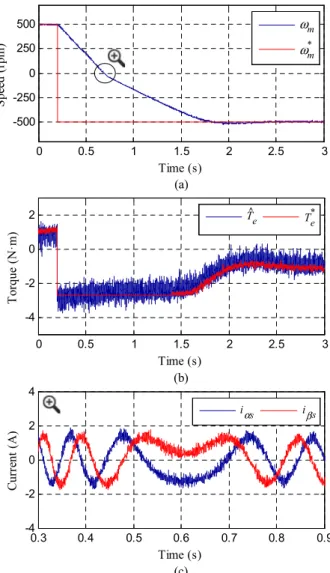
A reversal speed test is afterwards generated, and a change in the reference speed from 500 to –500 rpm is forced. The change is imposed at t=0.2 s, and the results are shown in Fig. 9. The system is again operated in open-phase post-fault procedure, being null the load torque imposed by the DC machine. Appropriate tracking is again observed in the speed and the estimated electrical torque evolution, as it can be seen in Figs. 9(a) and 9(b), respectively, and the stator current performance in the α–β plane around the zero-crossing speed operating point
is shown in detail in Fig. 9(c).
The transition between pre- and post-fault operation is analyzed in Fig. 10, where an open-phase fault is generated in phase ‘a’ using the power relay at t=0.2 s with a constant speed of 500 rpm and the system is instantaneously reconfigured. Upper plots show the speed evolution while lower figures display the estimated electrical torque response considering a demanded load torque of 28%, 56% and 70% of the nominal one in Figs. 10(a), 10(b) and 10(c), respectively. It is found that the fault occurrence does not affect the speed operation and the torque reference is accurately followed when the multiphase drive is working in the low load torque condition (TL=0.28·Tn),
Fig. 10(a). A quite similar situation (not exactly the same because a small deviation on the reference speed tracking is obtained just after the fault occurrence) is observed when the load torque is about 56% of the nominal one, Fig. 10(b), which corresponds to the maximum controllable post-fault open-phase torque operation when the minimum copper loss post-fault control criterion is used. On the contrary, the proposed DTC scheme is not able to control the mechanical speed when the
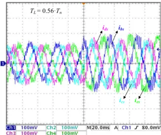
applied load torque exceeds the maximum controllable one in post-fault operation, as it is shown in Fig. 10(c). The obtained healthy stator currents before and after the fault are shown in Fig. 11, where an increment in their magnitudes is noticed to compensate the open-phase faulty situation; the magnitude of ‘b’ and ‘e’ stator currents are equal and larger than the magnitude of stator currents in ‘c’ and ‘d’ phases, which is in accordance with the minimum copper loss criterion [10].
The low speed operation of the drive is then observed in Fig. 12, where a constant reference speed of 50 rpm is maintained from pre- to post-fault operation with constant load torques of 28% and 56% of the nominal one, Fig. 12(a) and 12(b), respectively. Appropriate tracking of the reference speed (upper figures) and the electrical torque (lower plots) is obtained.
The obtained performance proves that the proposed DTC controller is effective for managing the open-phase post-fault operation of the five-phase IM drive. Note that the current ripple
TL = 0.56·Tn
ibs
ics
ids
ies
Fig. 11. Healthy stator phase currents when the open-phase fault appears and instantaneous control reconfiguration is used. The applied speed reference is 500 rpm and the demanded load torque is about 56% of the nominal one.
(a) (b) ωm ω*m Sp ee d (r pm ) 0 25 50 75 100 ωm ω* m Fault Occurrence Time (s) 0 0.2 0.4 0.6 0.8 1 1.2 TL = 0.28·Tn 0 0.2 0.4 0.6 0.8 1 1.2 ωm ω* m TL = 0.56·Tn ωm ω* m Fault Occurrence Time (s) 0 0.2 0.4 0.6 0.8 1 1.2 Sp ee d (r pm ) 0 25 50 75 100 Te Te* TL = 0.28·Tn Fault Occurrence Te Te* Time (s) 0 0.2 0.4 0.6 0.8 1 1.2 -1 0 1 2 3 4 5 To rq ue (N ·m ) ^ Te Te* Time (s) 0 0.2 0.4 0.6 0.8 1 1.2 Te Te* TL = 0.56·Tn Fault Occurrence -1 0 1 2 3 4 5 To rq ue (N ·m ) ^
Fig. 12. Low speed operation of the five-phase drive using the proposed DTC controller. The reference speed is set to 50 rpm, while load torques of (a) 28% and (b) 56% of the nominal one are applied. The speed response and the estimated electrical torque are depicted in the upper and lower plots, respectively. The open-phase fault is forced at t=0.2 s.
(a) (b) 0 100 200 300 400 500 600 4200 4300 4400 4500 4600 Speed (rpm) A vg . S w itc hi ng F re qu en cy (H z) TL = 0 TL = 0.56·Tn 0 100 200 300 400 500 600 3800 3900 4000 4100 4200 Speed (rpm) A vg . S w itc hi ng F re qu en cy (H z) TL = 0 TL = 0.56·Tn
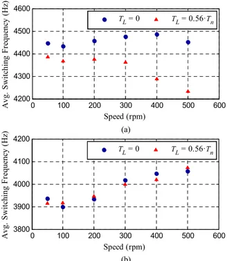
Fig. 13. Obtained average switching frequency using the proposed DTC controller in (a) healthy and (b) faulty operation when different load torques and reference speeds are applied.
is higher in DTC compared to other FOC-based control methods for similar five-phase IM drives (see [12]). However, the DTC technique provides a simpler modification of the post-fault control scheme to preserve the controllability of the system. This is an interesting characteristic in favor of the DTC method in applications where the highest reliability must be preserved and the drive must be operated in safety conditions until a corrective maintenance is carried out.
Fig. 13 shows finally the obtained average switching frequency using the proposed DTC technique. Different load torques (zero and 56% of the nominal one) and reference speeds (50, 100, 200, 300, 400 and 500 rpm) are applied, and the average switching frequency is obtained from the number of
IGBT gates’ pulses per second. It is interesting to note that the value is higher in healthy than in post-fault operation (see Fig. 13(a) and Fig. 13(b), respectively). This is an interesting benefit of the proposed DTC method that reduces the thermal stress in the operating IGBT devices during the faulty operation, where the obtained switching frequency remains nearly constant with applied load torques and does not vary as much as in healthy operation.
V. CONCLUSIONS
The recent interest in multiphase drives from the research community is due to, among other reasons, their high fault-tolerant capability. Field oriented control and predictive control schemes have been recently extended to the multiphase drive case, where their interests have been analyzed in healthy and open-phase faulty operation modes. DTC has been also proposed in recent times in five-phase induction motor drives during the normal operation of the system, but its utility managing the open-phase fault operation of the drive has not been stated yet. This paper extends the DTC technique to the open-phase fault operation of a symmetrical five-phase induction motor drive. Obtained experimental results analyze the performance of the proposed controller during the faulty operation of the drive, concluding that the speed, torque and flux references are maintained after the fault occurrence if the applied load torque is within the maximum torque that the post-fault control scheme can manage.
REFERENCES
[1] E. Levi, “Advances in Converter Control and Innovative Exploitation of Additional Degrees of Freedom for Multiphase Machines,” IEEE Trans. Ind. Electron., vol. 63, no. 1, pp. 433-448, Jan. 2016.
[2] F. Barrero and M. Duran, “Recent Advances in the Design, Modeling and Control of Multiphase Machines – Part 1,” IEEE Trans. Ind. Electron.,
vol. 63, no. 1, pp. 449-458, Jan. 2016.
[3] M. Duran and F. Barrero, “Recent Advances in the Design, Modeling and Control of Multiphase Machines – Part 2,” IEEE Trans. Ind. Electron.,
[4] A.S. Abdel-Khalik, S. Ahmed, A.A. Elserougi and A.M. Massoud, “Effect of Stator Winding Connection of Five-Phase Induction Machines on Torque Ripples Under Open Line Condition,” IEEE/ASME Trans.
Mechatronics, vol. 20, no. 2, pp. 580-593, Apr. 2015.
[5] A.S. Abdel-Khalik, M.A. Elgenedy, S. Ahmed and A.M. Massoud, “An Improved Fault-Tolerant Five-Phase Induction Machine Using a Combined Star/Pentagon Single Layer Stator Winding Connection,”
IEEE Trans. Ind. Electron., vol. 63, no. 1, pp. 618-628, Jan. 2016.
[6] I. Gonzalez-Prieto, M.J. Duran, H.S. Che, E. Levi, M. Bermúdez and F. Barrero, “Fault-Tolerant Operation of Six-Phase Energy Conversion Systems With Parallel Machine-Side Converters,” IEEE Trans. Power
Electron., vol. 31, no. 4, pp. 3068-3079, Apr. 2016.
[7] M. Darijevic, M. Jones and E. Levi, “An Open-End Winding Four-Level Five-Phase Drive,” IEEE Trans. Ind. Electron., vol. 63, no. 1, pp. 538-549, Jan. 2016.
[8] M. Jones, S.N. Vukosavic, D. Dujic and E. Levi, “A Synchronous Current Control Scheme for Multiphase Induction Motor Drives,” IEEE Trans.
Energy Convers., vol. 24, no. 4, pp. 860-868, Dec. 2009.
[9] C.S. Lim, E. Levi, M. Jones, N.A. Rahim and W.P. Hew, “FCS-MPC-Based Current Control of a Five-Phase Induction Motor and its Comparison with PI-PWM Control,” IEEE Trans. Ind. Electron., vol. 61, no. 1, pp. 149-163, Jan. 2014.
[10] H. Guzman, M.J. Duran, F. Barrero, B. Bogado and S. Toral, “Speed Control of Five-Phase Induction Motors With Integrated Open-Phase Fault Operation Using Model-Based Predictive Current Control Techniques,” IEEE Trans. Ind. Electron., vol. 61, no. 9, pp. 4474-4484, Sep. 2014.
[11] H. Guzman, F. Barrero and M.J. Duran, “IGBT-Gating Failure Effect on a Fault-Tolerant Predictive Current-Controlled Five-Phase Induction Motor Drive,” IEEE Trans. Ind. Electron., vol. 62, no. 1, pp. 15-20, Jan. 2015.
[12] H. Guzman, M.J. Duran, F. Barrero, L. Zarri, B. Bogado, I. Gonzalez-Prieto and M.R. Arahal, “Comparative Study of Predictive and Resonant Controllers in Fault-Tolerant Five-phase Induction Motor Drives,” IEEE
Trans. Ind. Electron., vol. 63, no. 1, pp. 606-617, Jan. 2016.
[13] “DTC: A motor control technique for all seasons” ABB Group, Zurich, Switzerland, 2015 [Online]. Available: http://library.e.abb.com/public/0 e07ab6a2de30809c1257e2d0042db5e/ABB_WhitePaper_DTC_A4_201 50414.pdf.
[14] L. Zheng, J.E. Fletcher, B.W. Williams and X. He, “A Novel Direct Torque Control Scheme for a Sensorless Five-Phase Induction Motor Drive,” IEEE Trans. Ind. Electron., vol. 58, no. 2, pp. 503-513, Feb. 2011.
[15] L. Gao, J.E. Fletcher and L. Zheng, “Low-Speed Control Improvements for a Two-Level Five-Phase Inverter-Fed Induction Machine Using Classic Direct Torque Control,” IEEE Trans. Ind. Electron., vol. 58, no. 7, pp. 2744-2754, Jul. 2011.
[16] JR. Fu and T.A. Lipo, “Disturbance-free operation of a multiphase current-regulated motor drive with an opened phase,” IEEE Trans. Ind.
Appl., vol. 30, no. 5, pp. 1267-1274, Sep./Oct. 1994.
[17] A. Tani, M. Mengoni, L. Zarri, G. Serra and D. Casadei, “Control of Multiphase Induction Motors With an Odd Number of Phases Under Open-Circuit Phase Faults,” IEEE Trans. Power Electron., vol. 27, no. 2, pp. 565-577, Feb. 2012.
[18] H.M. Ryu, J.W. Kim and S.K. Sul, “Synchronous-Frame Current Control of Multiphase Synchronous Motor Under Asymmetric Fault Condition Due to Open Phases,” IEEE Trans. Ind. Appl., vol. 42, no. 4, pp. 1062-1070, Jul./Aug. 2006.
[19] M. Bermudez, I. Gonzalez-Prieto, F. Barrero, M.J. Duran and X. Kestelyn, “Open-Phase Fault Operation of 5-Phase Induction Motor Drives using DTC Techniques,” Industrial Electronics Society, IECON
2015 – 41st Annual Conference of the IEEE, Yokohama, 9-12 Nov. 2015.
[20] A.G. Yepes, J.A. Riveros, J. Doval-Gandoy, F. Barrero, O. Lopez, B. Bogado, M. Jones and E. Levi, “Parameter Identification of Multiphase Induction Machines With Distributed Windings—Part 1: Sinusoidal Excitation Methods,” IEEE Trans. Energy Convers., vol. 27, no. 4, pp. 1056-1066, Dec. 2012.
[21] J.A. Riveros, A.G. Yepes, F. Barrero, J. Doval-Gandoy, B. Bogado, O. Lopez, M. Jones and E. Levi, “Parameter Identification of Multiphase Induction Machines With Distributed Windings—Part 2: Time-Domain Techniques,” IEEE Trans. Energy Convers., vol. 27, no. 4, pp. 1067-1077, Dec. 2012.