Science Arts & Métiers (SAM)
is an open access repository that collects the work of Arts et Métiers Institute of
Technology researchers and makes it freely available over the web where possible.
This is an author-deposited version published in:
https://sam.ensam.eu
Handle ID: .
http://hdl.handle.net/10985/14598
To cite this version :
Gabriel GUENOUN, Jean-Yvon FAOU, Gilles REGNIER, Nicolas SCHMITT - Thermal cycling of
cold-pressed PTFE compacts: Reversible and irreversible behavior - Polymer Testing - Vol. 75,
p.99-106 - 2019
Any correspondence concerning this service should be sent to the repository
Administrator :
[email protected]
Test Method
Thermal cycling of cold-pressed PTFE compacts: Reversible and irreversible
behavior
Gabriel Guenoun
a,b,c,*, Jean-Yvon Faou
b, Gilles Régnier
c, Nicolas Schmitt
a,d, Stéphane Roux
a aLMT, ENS-Paris-Saclay, CNRS, Univ. Paris-Saclay, 61 Avenue du Président Wilson, 94235, Cachan Cedex, FrancebSaint-Gobain Research Paris, 39 Quai Lucien Lefranc, 93303, Aubervilliers Cedex, France cPIMM, Arts et Métiers ParisTech/CNRS/CNAM, 151 boulevard de l’Hôpital, 75013, Paris, France dESPE, Univ. Paris-Est Créteil Val-de-Marne, Place du 8 mai 1945, 93203, Saint-Denis, France
Keywords: PTFE Dilatometry Thermal cycle Residual stresses Irreversible behavior Anisotropy A B S T R A C T
Cold uniaxial pressed PTFE compacts were subjected to thermal cycles of increasing maximum temperature below melting temperature, and thermal expansion was followed in both the compaction and transverse di-rections. The measurements reveal that thermal expansion consists of two distinct contributions: i) an irrever-sible part that is controlled only by the maximum temperature experienced by the sample, and ii) a reverirrever-sible, or thermo-elastic, part that is observed while cycling below the maximum temperature. Moreover, both of these thermal strains exhibit marked anisotropy, resulting from the cold oedometric compaction of the sample. A quantitative analysis of these eigenstrains is proposed, following a formal analogy with elasto-plasticity. Finally, it is shown that such behavior is specific to cold-pressed compacts as sintered samples exhibit isotropic and purely reversible thermo-elastic behavior.
1. Introduction
Well-known for its remarkable properties, Polytetrafluoroethylene (PTFE) is employed in various engineering applications. The main as-sets of this material are its extremely low coefficient of friction, high thermal stability, good electrical insulation, resistance to corrosion, hydrophobicity and biocompatibility [1–3]. This unique semi-crystal-line polymer owes its attributes to the presence of fluorine atoms all around the carbon chain. Fluorine is responsible for the chemical in-ertness of the polymer and for the low friction as the polymer chains do not bond to each other [4,5]. PTFE polymerizes in extended chain configuration leading to very high crystallinity (more than 90%) whereas melt-crystallized PTFE is much less crystalline (around 50%) due to chain entanglements [6]. Several phase transitions exist in PTFE at atmospheric pressure. At room temperature two first-order crystal-line phase transitions occurs, namely Triclinic phase II - Hexagonal phase IV at 19 °C and Hexagonal phase IV - Pseudo-hexagonal phase I at 30 °C [7]. Two second-order transitions occur in PTFE. The -transition around −100°C seems to correspond to the glass transition of mobile amorphous fraction (MAF), and the -transition around 130 °C to the glass transition of rigid amorphous fraction (RAF) [8,9].
This polymer is processed from powder with very specific methods such as billet pressing and sintering, ram extrusion and film casting.
The choice of the manufacturing process and of type of PTFE powder is made according to the application [10]. There are two types of poly-merization of TFE available, leading to different pure PTFE resins: emulsion polymerized PTFE and suspension polymerized PTFE. From the former, PTFE dispersion and fine powder are obtained. From the latter, granular PTFE is obtained. The granular PTFE can be separated into two categories: low flow and free flow resins depending on the size of the grains (fine and large respectively). All of these powders can be mixed with fillers.
PTFE powder pressing, sintering and skiving is used to create films to make bearing components. Low flow (also called fine cut) resin is pressed into a die to form a cylinder called a “billet” [11]. The preform is then sintered to reduce and homogenize porosity created during compaction and to blur the powder grain interfaces thanks to chain entanglements, and thereby enhance the final mechanical properties. During the thermal treatment large strains occur due to the melting and recrystallization of the polymer [12]. Thermal gradients coupled to these strains lead to strain incompatibilities, and hence stress con-centration that could damage the billet [13].
During the sintering cycle, the PTFE experiences significant strains. A convenient concept to characterize the thermo-mechanical behavior is that of eigenstrains, namely the strain that would be measured in the polymer if microstructure and temperature were always spatially *Corresponding author. LMT, ENS-Paris-Saclay, CNRS, Univ. Paris-Saclay, 61 Avenue du Président Wilson, 94235, Cachan Cedex, France.
E-mail address:[email protected](G. Guenoun).
uniform (and hence devoid of any kinematic incompatibility). The overall eigenstrain of PTFE is due to several physical mechanisms such as thermal expansion dependent on the crystallinity content, melting, crystallization [14], gas diffusion and porosity closure [12]. This ei-genstrain is observed to be anisotropic as induced by the uniaxial compaction that forms a transverse isotropic material. This paper aims to study the overall eigenstrain of a PTFE compact through arbitrary thermal histories without melting, and to unravel the role of different mechanisms.
In section2, dilatometry measurements during thermal cycles reveal an unexpected evolution of the eigenstrain, formally similar to elasto-plasticity, that can be decomposed into reversible and irreversible parts. A descriptive model is then developed in section3to express this strain as a function of the maximum experienced temperature. The tensorial aspect of the reversible and irreversible parts of the eigenstrain is stu-died and reveals the anisotropy induced by the initial cold pressing. This observation translates into a swelling of the material as a result of internal stress relaxation, suggesting the creation of micro- or meso-porosity.
2. Experimental
In order to better understand the strain induced by thermal treat-ment, uniaxially compacted PTFE samples were subjected to different heating/cooling histories, and followed through dilatometry. To avoid the very large dimensional changes that go together with melting, un-less explicitly mentioned, the maximum temperature was kept below that of the melting transition.
2.1. Material
A fine cut granular PTFE resin was chosen. This type of resin is currently used for molding and is suitable for compounding with fillers because of the small particle size which is in the range of 20–100 μm [10]. The initial crystallinity content is above 90%.
2.2. Thermal characterization
A calorigram of compacted PTFE is shownFig. 1. This experiment
was performed on a differential scanning calorimeter (DSC) Q10 from TA instruments with a 5 mg sample heated up at 20 °C/min. The ca-lorigram shows that the melting temperature of this resin is close to 340 °C. It highlights an inflexion close to 250 °C revealing a diffuse
phase transition below the melting peak that could correspond to the melting of smaller crystals.
2.3. Sample preparation
The different specimens were prepared at the same time with PTFE resin from the same batch. PTFE powder is recommended to be con-ditioned at 21–25 °C at atmospheric pressure for better compaction [10]. These precautions ensure very reliable and reproducible experi-ments.
The powder was uniaxially compacted at 50 MPa in a die using a universal testing machine to form cubes of 8 mm long edges (Fig. 2a). The PTFE cubes were removed from the die and kept at room
Fig. 1. DSC melting peak of compacted PTFE powder. A zoom is shown at lower
temperatures where a change is observed around 250 °C.
Fig. 2. (a) PTFE powder uniaxially compacted inside a die to form small PTFE
cubes; (b) dimension variations of the cubic sample measured during a given thermal treatment in the compaction direction (CD) and in the transverse di-rection (TD).
temperature for at least 2 days to allow entrapped air to diffuse out before being tested.
2.4. Microstructural analysis
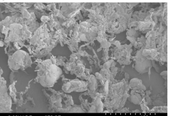
On the SEM image of the PTFE powder inFig. 3, PTFE particles in the range of 20–100 μm can be observed. Those particles appear as fluffy flakes with a complex sub-microstructure (Fig. 3b). The in-dividual size of those elements is in the range of 100–500 nm. There-fore, two types of porosities can exist in the material after compaction, one macro-porosity to be linked with the particles size itself and a
micro-porosity at a submicrometric scale.
The compaction pressure controls the level of final macro-porosity as shown inFig. 4indicating the density of the PTFE sample as a function of the compaction pressure. For a compaction pressure of 50 MPa, the level of macro-porosity can be neglected as the density is not increasing at higher pressures. Moreover, no porosity was observed using X-ray computed microtomography with 1 μm resolution.
Another impact of the compaction is the induced orientation tex-ture. As the PTFE is uniaxially compacted in a mold, the crystals are reoriented in the transverse directions (perpendicular to the compac-tion direccompac-tion). A Herman's orientacompac-tion factor for the chains orientacompac-tion of −0.1 was determined in the compaction direction via X-Ray dif-fraction [16].
2.5. Dilatometric measurements
A thermomechanical analyzer TMA/SDTA 840 from Mettler Toledo was used to perform the dilatometry tests. The PTFE cubic specimen was placed inside an oven and a prescribed temperature history was applied. The thermal cycle was chosen to be slow enough to ensure good temperature homogeneity inside the sample. The temperature difference was limited to 2 °C between the core and the edge of the sample for a heating rate of 1.5 °C/min (result obtained by thermal si-mulation). The force applied by the probe on the sample was main-tained at 0.01 N. Assuming a homogeneous state (from quasi-static temperature variations) the true (or logarithmic) strain iiin directioni is estimated from the displacementuiand initial sizeLi, as
+u L
log 1
ii i
i (1)
all along the thermal cycle (no implicit summation on indexi). Note that this is the mean strain from the initial state considered as a re-ference, and the current state. Resorting to true strains allows us to change reference if so desired by mere subtraction of the strain of the newly chosen reference state. Because of the homogeneity assumption and the assumption that the applied force is null, the measured strains are actually “eigenstrains” for constitutive law formulation of the thermo-mechanical behavior.
The dilatometry test was performed on different samples, some to test the compaction direction (CD) and others for the transverse di-rection (TD) as the samples are transversely isotropic due to the uni-axial compaction (Fig. 2b).
From this transverse isotropy symmetry, the strain tensor is ex-pected to be fully characterized by the TD and CD strain components. Choosing the third axis along the CD, the strain tensor assumes the following form = 0 0 0 0 0 0 TD TD CD (2)
In this study, successive thermal cycles with an increasing maximal temperature were chosen to investigate the strain behavior of com-pacted PTFE powder under thermal treatment below melting tem-perature. The thermal path consisted of three successive cycles reaching, respectively, 175 °C, 250 °C and 300 °C (Fig. 5a). The heating and cooling rates were 1.5 °C/min and the holding time at maximal temperature was 30 min. The PTFE specimen was held for 5 min at
Fig. 3. SEM observation of the PTFE powder used for the experiments. (b) is a
zoom of (a). The images are coming from an earlier work [15].
Fig. 4. Density of the PTFE sample as function of the applied pressure during
25 °C before each new cycle. A final cycle ended the thermal path to complete the sintering of the sample, with the same heating and cooling rates with a longer plateau of 100 min above the melting temperature at 370 °C. In this paper, = T T0, refers to the temperature variation
counted from the reference temperatureT0 which was chosen to be
25 °C.
3. Results and discussion
3.1. Reversible and irreversible eigenstrain decomposition
Fig. 5b shows the true strain curves for CD and TD as function of time.
The major strain variations are observed during the last thermal cycle at the end of the test and correspond respectively to melting and crystallization of PTFE compact as crystalline phase is denser than amorphous phase. The strain due to crystallization stretches on a longer temperature range than melting. The melting mechanism is essentially
controlled by the crystallite size distribution of the PTFE resin [17]. In contrast, the crystallization is ruled by different mechanisms that de-pend on the cooling rate. The crystallization mechanism is a complex and not fully understood topic due to the presence of secondary crys-tallization [18,19]. Because of this, the present study does not address melting and crystallization mechanisms, but rather focuses on the earlier stages prior to melting which, although simpler, reveal un-expected manifestations of stress relaxation already observed by Canto et al. [12]. Nevertheless, the last cycle that goes above melting tem-perature is shown in some of the following figures in order to see the very strong effect of sintering.
The CD and TD strains versus time are shown inFig. 5b with the
reference chosen at the initial state at temperatureT0. A first
observa-tion is that the CD and TD direcobserva-tions show very different strains, even in the first three cycles. This means that the cold uniaxial compaction process induces pronounced anisotropy [13,15,20,21]. After successive cycles, the sample tends to dilate in the compaction direction (CD), and to contract in the transverse direction (TD), and the apparent coeffi-cient of thermal expansion appears to differ in these two directions, again a manifestation of compaction-induced anisotropy.
When plotted as a function of temperature rather than time, as done
inFig. 6, it is observed again that sintering has a very major impact on
the dilatometric behavior and, as mentioned above, the present study focuses on the pre-melting behavior, as shown inFig. 6b and d. In this first subsection, any of the principal eigenstrain, CD or TD, is con-sidered independently without index.
These figures first show that, even in the absence of phase trans-formation, the thermo-mechanical behavior is not a reversible thermal dilation, in as much as the thermal eigenstrain is not given by a single function of the temperature variation . However, when the tempera-ture variation is decreased from any previously experienced peak value , then a one-to-one relationship between eigenstrain and is observed, as can be seen for all branches Bi Ai inFig. 6b or 6d. These curves
seem, however, to depend on but in a rather simple way: mere
translations along the strain axis allow all reversible branches to su-perimpose exactly. This observation suggests that two parameters are needed to characterize the thermo-mechanical eigenstrains: 1) the current (relative) temperature, , along a reversible path and 2) the maximum previously experienced relative temperature,
=
t t
( ) max[ ( )]
t t (3)
that controls the overall translation of the thermal response. Moreover, an additive decomposition of the overall thermal eigenstrain into two contributions can be made:
= +
t t t
[ ( )] rev( ( )) irr( ( )) (4)
where rev is the thermal expansion that only depends on the
in-stantaneous relative temperature, , and irris an irreversible
eigen-strain that only depends on the maximum of the previously encountered relative temperature. Note that the notation[ ( )]t refers to a functional dependence over the entire (past) temperature history, whereas( ( ))t refers to a function dependence on the scalar instantaneous variation of temperature occurring at timet.
This additive strain decomposition is formally reminiscent of the one encountered in (rate-independent) elasto-plasticity, but where re-lative temperature plays the role of stress. Introducing the functions defining the reversible and irreversible eigenstrains for i {CD, TD}:
= = f g ( ) ( ) ( ) ( ) i i i i rev irr (5)
It is easy to have access these functions experimentally by noting the following property: In the thermal cycles, one can select those instants of time notedt+where ( )t+ = ( )t+. For those, the eigenstrain obeys Fig. 5. Thermal cycle applied to the small PTFE block (a) and related measured
true strain in compaction direction (CD) and transverse direction (TD) as function of time (b).
= = + + + + + + + + t t t t f t g t ( ( )) ( ( )) ( ( )) ( ( )) ( ( )) ( ( )) i i i i i i envel rev irr (6)
This relation is the “envelope” curve (path O A1 A2 A3) of
Fig. 6b or 6d and drawn in purple. Conversely, the longest descending temperature ramp (A3 B3), corresponds to instants of time notedt
for which is frozen to the temperature reached at point A3, 3, and
hence = = + + t t t f t g ( ( )) ( ( )) ( ( )) ( ) ( ( )) ( ) i i i i i i desc rev irr 3 3 (7)
Thus, the reversible eigenstrain function is obtained (for < 3) as
=
f ( )i idesc( ) idesc(0) (8)
while the irreversible part is
=
gi( ) ienvel( ) fi( ) (9)
An illustration of the evaluation of these eigenstrains in the TD and CD directions is given inFig. 7a and b.
The irreversible part of the eigenstrain gi is very close to 0 up to about 60 °C, just as if the PTFE sample had already experienced such a maximum temperature in its past. In some way, the function g encodes a memory of the sample. However, it may be that the effect of
temperature can also be obtained with time through similar, but now thermally activated, irreversible microscopic events. This temperature-time analogy has, however, not been studied herein.
Both CD and TD directions obey the same formalism, thereby re-ducing the full history dependent behavior to four (reversible and ir-reversible parts, CD and TD directions) scalar functions. However, they show very different quantitative contributions. This sheds some light on the subtle question of anisotropy.
The quantification of anisotropy can be done from the direction of the path followed by eigenstrains in strain space. The symmetry of the problem reduces the tensorial nature of the strain tensor to only two components CD and TD.
From 200 °C and above, some new features that were not visible at lower temperatures begin to appear. First, the reversible part is very close to linear up to 200 °C, and markedly non-linear (yet still re-versible) above. Second, a more and more pronounced gap appears at temperature reversal points of the cycles (Fig. 6), suggesting the pro-gressive relevance of viscous effects that could be neglected at lower temperatures [22]. Third, the irreversible part of the eigenstrain seem to reveal higher and higher densification, which may be due to a dif-ferent phenomenon than in the low temperature regime where a net expansion is observed. One may speculate that the collapse of nano-cavities may take place and contribute to the irreversible mechanism at such high temperatures. The melting of smaller crystals suggested by
the calorigram shown inFig. 1around 250 °C may help close
nano-cavities.
Fig. 6. (a) Measured true strain in TD; (c) Measured true strain in CD; (b) zoom of (a) and (d) zoom of (c) on the three first cycles prior to melting, where the followed
path is O−A1−B1−A1−A2−B2−A2−A3−B3− A3. Branches Ai− Biappear to be reversible behaviors valid when the temperature remains lower than that of
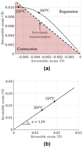
The plots of the irreversible and thermo-elastic (reversible) eigen-strains in CD and TD against each other are shown inFig. 8. In such plots, an isochoric (isovolumic) transformation is a straight line of slope −2 because of the transversely isotropic character of the specimen.
InFig. 8a, the irreversible eigenstrain contribution corresponds at
low temperature to a fixed direction in strain space, so that the ratio of volumetric to deviatoric strain is constant and positive (meaning an irreversible swelling). Because no phase transformation is expected in this range of temperature, such an effect could correspond to the opening of nanopores. The scale of those pores is termed nano to signify submicrometric, as they are not seen in x-ray computed micro-tomography. It would be interesting to use small angle x-ray scattering to investigate this point. At about 200 °C, a contraction character begins to set in and, as mentioned above, it could correspond to the closing of nano-cavities.
The thermo-elastic eigenstrain contribution shown inFig. 8b is re-markably linear and reveals anisotropic dilation. Unlike the irreversible eigenstrain, this behavior remains linear at higher temperatures (at 250 °C and above). This indicates that the origin of the anisotropy is different for the reversible and irreversible contributions. For the re-versible eigenstrain, which can be associated to the thermal expansion, the anisotropy may be induced by the crystalline texture caused by the compaction. A possible origin of the irreversible eigenstrain anisotropy is discussed in the next subsection.
3.2. Proposed mechanisms for irreversible eigenstrains
In order to distinguish the respective contribution of two categories of porosities (macro and micro) mentioned insubsection 2.4, varying the
compaction pressure provided some insight. At the highest compaction pressure considered in this study, 50 MPa, no macro-pores are observed to remain in the compacted sample. In contrast, we supposed that for lower pressures, (pressures down to 10 MPa were tested) some
macro-porosity is left after compaction as the density is not saturated (Fig. 4). However, it is observed to be stable when the temperature is varied, up to temperature close to fusion, where surface tension leads to closure of the pores. For lower temperatures, macro-pores when they exist seem not to play any significant role. Besides, for these different compaction pressure, the dilatometry experiment revealed a similar irreversible expansion behavior. Therefore, the latter characteristic is believed to be due to the densification that takes place at the nanoscale. This is con-sistent also with the observation that no porosity became visible at the 1 μm scale resolution from tomography of samples compacted at 50 MPa, after the thermal cycles of the dilatometry experiment. The irreversible expansion due to the thermal cycle did only generate sub-micrometric pores.
From the above observations, it is deduced that the mechanism for the irreversible expansion of the sample:
- has to find its origin in the initial cold mechanical compaction - has to result from the deformation of the constitutive particles - has to involve a stored mechanical energy that will allow to compete
with the surface tension cost of creating a pore
- has to correspond to a metastable state becoming unstable under a temperature rise.
These points led us to propose a mechanistic scenario whereby the closing a micro-pores goes together with an internal stress field (where the potential elastic energy is stored).
Fig. 7. Evaluation of the overall eigenstrain split in the reversible and
irre-versible contributions for (a) the TD direction and (b) the CD direction.
Fig. 8. Residual stress relaxation in CD as function of the residual stress
Porosity (at least supermicrometric) disappears during compaction
under a macroscopic oedometric strain, as sketched in Fig. 9a.
Ele-mentary particles are thus deformed plastically, so that they come to-gether and stick from interparticle adhesion (Fig. 9b), that opposes residual stress due to the deformation of particles. The oedometric compression induces polarization of these internal stresses, as shown in (b). As temperature increases, such contacts may snap open, with a local kinematics that is illustrated in Fig. 9c. Even if locally rather
complex rearrangement of grains may exist, the net effect of a local contact opening can be inferred from the classical “Eshelby” problem, where an inclusion embedded in an elastic matrix undergoes a plastic strain [23]. Actually, all complications coming from the local details of such events can be accounted for by a multipolar expansion of Eshelby type terms vanishing with distance to the inclusion centerrasr with
dwhere =d 3is the space dimension. The dominant contribution is the only one that survives at the macroscopic scale and is precisely the usual “Eshelby” solutions, that contains three elementary purely de-viatoric components polarized along x, y orzand one isotropic term (dilation of the inclusion). A finite density of such inclusions will pro-duce, at a macroscopic scale, a strain reflecting the symmetry of the locally locked residual stress. In our case, it is expected that the mac-roscopic strain released by these local contact break-ups is simply op-posed to the oedometric compaction, in agreement with the observed irreversible thermal eigenstrain.
It is important to note that this elementary stress field involves a tension at the scale of the micro-pore (nm range) that has to be counter-balanced by a compression at a further distance. However the latter stress field decreases very fast with the distance r to the initial pore (Eshelby outer field decaying as r 3). This is to be contrasted with a
structural internal stress field (such as a skin compression balanced by a bulk traction as produced e.g. by thermal tempering or shot-peeing). As a result, it is not possible to reveal these internal stresses by cutting or drilling because the net effect of introducing a free surface has to bal-ance out at the scale of the micro-pores. Hence ideally no more than a nano-roughness should be expected. Nevertheless, when a spatially uniform distribution of such locked-in internal stresses is freed a uni-form macroscopic strain is expected, consistently with the observed irreversible dilation.
At high temperature, the elastic properties of the material are ex-pected to soften, (possibly involving viscous relaxation) and surface tension of nanocavities may proceed with a similar mechanism.
3.3. Sintered PTFE
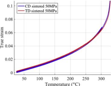
In order to highlight the specificities of the green compact, a similar dilatometry experiment was performed on a compacted PTFE sample first sintered with a thermal cycle above melting temperature and 100 min hold time at 370 °C. Then, a similar temperature cycling (as shown inFig. 2a) was applied to the sintered specimen. The strains in CD and TD corresponding to the three thermal cycles are shown in
Fig. 10 as a function of the temperature. Those strains reveal no
Fig. 9. Sketch representing PTFE particles uniaxially compacted (a). The
par-ticles deform and trap residual stress. The compacted sample is removed from the mold (b) and is relaxed by applying a thermal treatment (c).
Fig. 10. Measured true strain in CD and TD for a sintered PTFE cube during
irreversibility during the successive cycles. This suggests that most re-sidual stresses have been relaxed after the melting of PTFE, and no residual stress susceptible to be relaxed by thermal activation has been regenerated during the recrystallization. The sintering of PTFE leads to the loss of granular structure as the particles interfaces are merged during melting and recrystallization. This could also explain that no residual stress can be trapped in the same way as for the compacted nascent powder.
Also, the behavior appears to be isotropic [12], the expansion comes mainly from the amorphous phase which is more likely to be isotropic, and the recrystallized PTFE is much more amorphous (around 50%) than nascent PTFE (more than 90% crystalline). It is then also im-portant to note that the thermal expansion is very different from sin-tered PTFE and green compact of PTFE due to this difference of crys-tallinity content, so that these results cannot be used to compare with the reversible part of the unsintered sample. The thermal expansion stops being linear with temperature above 130 °C, which may be due to the glass transition of RAF. This transition may impact sintered PTFE more than nascent PTFE as the amorphous fraction is much more im-portant after sintering [24]. Around 250 °C, the curvature of the strain may be explained by other phenomena such as melting of smaller crystals coming from secondary crystallization.
4. Conclusions
Compacted nascent PTFE powder presents a peculiar behavior under thermal cycling. In addition to a reversible thermo-elastic con-tribution, an irreversible contribution has been shown. The latter may be progressively erased by previous thermal treatment at higher and higher temperatures. Such behavior is formally reminiscent of an elasto-plastic behavior, with an additive decomposition of strains be-tween the reversible and irreversible parts. Moreover, both of these strains reveal anisotropic behavior that is due to the preceding cold compaction process of nascent PTFE powder. Remarkably, after sin-tering, the irreversible part disappears, and the anisotropy (that still exists in the microstructure) has no manifestation in the thermal cycles studied.
It is speculated that the irreversible part of the thermal eigenstrain is due to local stress relaxation mechanisms, occurring at a submicrometer scale. Above 250 °C, some other mechanisms appear that modify the strain behavior of PTFE, such as possible porosity closure.
To refine those observations and deepen the understanding of this phenomenon, it would be interesting to study the residual stress re-laxation of PTFE with different multiaxial compactions such as hydro-static or biaxial compaction. This should have an effect on the aniso-tropy of the relaxation strain by modifying the residual stress formation. Further investigations will be performed on the strain be-havior to study melting and crystallization of PTFE and the variation of thermal expansion during a complete sintering cycle.
Data availability
The raw data required to reproduce these findings cannot be shared at this time as the data also forms part of an ongoing study.
Acknowledgements
The authors would like to thank Saint-Gobain for sponsoring this work and especially Monika Brodesser, Ansgar Haeger, Georges Moineau, Xavier Brajer, René Gy and François Creuzet for their im-plication in the project. The authors would like to thank the ANRT for sponsoring this project as well.
Appendix A. Supplementary data
Supplementary data to this article can be found online athttps:// doi.org/10.1016/j.polymertesting.2019.01.018.
References
[1] S. Biswas, K. Vijayan, Friction and wear of PTFE—a review, Wear 158 (1992) 193–211.
[2] J.M. Cox, B.A. Wright, W.W. Wright, Thermal degradation of fluorine-containing polymers. Part I. Degradation in vacuum, J. Appl. Polym. Sci. 8 (1964) 2935–2950,
https://doi.org/10.1002/app.1964.070080636.
[3] J. Zhang, J. Li, Y. Han, Superhydrophobic PTFE surfaces by extension, Macromol. Rapid Commun. 25 (2004) 1105–1108,https://doi.org/10.1002/marc.200400065. [4] M.A. Golub, T. Wydeven, Reactions of atomic oxygen (O(3P)) with various polymer films, Polym. Degrad. Stabil. 22 (1988) 325–338, https://doi.org/10.1016/0141-3910(88)90004-3.
[5] E. Giannetti, Semi-crystalline fluorinated polymers, Polym. Int. 50 (2001) 10–26,
https://doi.org/10.1002/1097-0126(200101)50:110::AID-PI614 > 3.0.CO;2-W. [6] L. Melillo, B. Wunderlich, Extended-chain crystals: VIII. Morphology of
polytetra-fluoroethylene, Kolloid-Z. Z. Polym. 250 (1972) 417–425,https://doi.org/10.1007/ BF01507508.
[7] E.N. Brown, D.M. Dattelbaum, The role of crystalline phase on fracture and mi-crostructure evolution of polytetrafluoroethylene (PTFE), Polymer 46 (2005) 3056–3068,https://doi.org/10.1016/j.polymer.2005.01.061.
[8] G. Dlubek, A. Sen Gupta, J. Pionteck, R. Häßler, R. Krause-Rehberg, H. Kaspar, K.H. Lochhaas, Glass transition and free volume in the mobile (MAF) and rigid (RAF) amorphous fractions of semicrystalline PTFE: a positron lifetime and PVT study, Polymer 46 (2005) 6075–6089,https://doi.org/10.1016/j.polymer.2005.04. 090.
[9] G. Calleja, A. Jourdan, B. Ameduri, J.-P. Habas, Where is the glass transition temperature of poly(tetrafluoroethylene)? A new approach by dynamic rheometry and mechanical tests, Eur. Polym. J. 49 (2013) 2214–2222,https://doi.org/10. 1016/j.eurpolymj.2013.04.028.
[10] S. Ebnesajjad, Fluoroplastics, Volume 1: Non-melt Processible Fluoropolymers: the Definitive User's Guide and Data Book Plastics Design Library, Elsevier, 2014. [11] C. Frédy, R.B. Canto, N. Schmitt, S. Roux, R. Billardon, Modelling of the mechanical
behaviour of two pure PTFE powders during their compaction at room temperature, AIP Conference Proceedings, AIP, 2013, pp. 1246–1249, ,https://doi.org/10.1063/ 1.4812164.
[12] R.B. Canto, N. Schmitt, J. De Carvalho, R. Billardon, Experimental identification of the deformation mechanisms during sintering of cold compacted polytetra-fluoroethylene powders, Polym. Eng. Sci. 51 (2011) 2220–2235,https://doi.org/ 10.1002/pen.21994.
[13] L. Andena, M. Rink, F. Polastri, Simulation of PTFE sintering: thermal stresses and deformation behavior, Polym. Eng. Sci. 44 (2004) 1368–1378,https://doi.org/10. 1002/pen.20132.
[14] D.C. Bassett, R. Davitt, On crystallization phenomena in polytetrafluoroethylene, Polymer 15 (1974) 721–728,https://doi.org/10.1016/0032-3861(74)90024-X. [15] C. Frédy, Modeling of the Mechanical Behavior of Polytetrafluoroethylene (PTFE)
Compounds during Their Compaction at Room Temperature, PhD Thesis Université Pierre et Marie Curie-Paris, 2015.
[16] I.M. Ward, Structure and Properties of Oriented Polymers, Applied Science, London, 1975.
[17] J.D. Hoffman, G.T. Davis, J.I. Lauritzen, The rate of crystallization of linear poly-mers with chain folding, in: N.B. Hannay (Ed.), Treatise on Solid State Chemistry: Volume 3 Crystalline and Noncrystalline Solids, Springer US, Boston, MA, 1976, pp. 497–614, ,https://doi.org/10.1007/978-1-4684-2664-9_7.
[18] T. Ozawa, Nonisothermal crystallization of poly(tetrafluoroethylene), Bull. Chem. Soc. Jpn. 57 (1984) 952–955,https://doi.org/10.1246/bcsj.57.952.
[19] Y. Seo, Nonisothermal crystallization kinetics of polytetrafluoroethylene, Polym. Eng. Sci. 40 (2000) 1293–1297,https://doi.org/10.1002/pen.11257. [20] F. Li, V.M. Puri, Measurement of anisotropic behavior of dry cohesive and
cohe-sionless powders using a cubical triaxial tester, Powder Technol. 89 (1996) 197–207,https://doi.org/10.1016/S0032-5910(96)03184-1.
[21] S. Galen, A. Zavaliangos, Strength anisotropy in cold compacted ductile and brittle powders, Acta Mater. 53 (2005) 4801–4815,https://doi.org/10.1016/j.actamat. 2005.06.023.
[22] Y. Araki, Stress relaxation of polytetrafluoroethylene in the vicinity of its glass transition temperature at about 130°C, J. Appl. Polym. Sci. 9 (1965) 1515–1524,
https://doi.org/10.1002/app.1965.070090426.
[23] S. Nemat-Nasser, M. Hori, Micromechanics: Overall Properties of Heterogeneous Materials, North-Holland, Amsterdam; New York, 1993.
[24] Y. Araki, Thermal expansion coefficient of polytetrafluoroethylene in the vicinity of its glass transition at about 400°K, J. Appl. Polym. Sci. 9 (1965) 421–427,https:// doi.org/10.1002/app.1965.070090203.