People`s Democratic Republic of Algeria
The Ministry of Higher Education and Scientific Research
F
ERHAT ABBAS UNIVERSITY–
SETIF1
FACULTY
OF
TECHNOLOGY
THESIS
Presented in the Department of Electrotechnics
To obtain the diploma of
DOCTORATE OF SCIENCES
Option: electric networks
by
Khaled BELHOUCHET
TOPIC
Contribution to the study and improvement of the electric
performance of high voltage insulators
Presented publically in 22/02/2020 in front of the Jury:
GHERBI Ahmed Prof.at Ferhat ABBAS university of Setif -1- President
BAYADI Abdelhafid Prof.at Ferhat ABBAS university of Setif -1- Thesis supervisor
HAMOU Nouri Prof.at Ferhat ABBAS university of Setif -1- Examiner
MOULAI Hocine Prof.at Houari Boumediene university Algiers Examiner
TEGUAR Madjid Prof.at the National Polytechnic School, Algiers Examiner
This work has not previously been accepted in substance for any degree and is
not concurrently submitted in candidature for any degree.
Signed : ………... (BELHOUCHET Khaled) Date:...
STATEMENT 1
This thesis is being submitted in partial fulfilment of the requirements for the
degree of PhD
Signed : …………... (BELHOUCHET Khaled) Date: ...
STATEMENT 2
This thesis is the result of my own work/investigation, except where otherwise
stated. Other sources are acknowledged by explicit references.
Signed : …………... (BELHOUCHET Khaled) Date: ...
STATEMENT 3
I hereby give consent for my thesis, if accepted, to be available for
photocopying and for inter-library loan, and for the title and summary to be
made available to outside organisations.
arc constants in insulators flashover voltage using real-coded genetic algorithm approach”. The 8th National Conference on Electrical engineering (ICEE). EMP.
2013.
K. Belhouchet, A. Bayadi, ME. Bendib, “Artificial neural networks (ANN) and genetic algorithm modeling and identification of arc parameter in insulators flashover voltage and leakage current , 4th International Conference on Electrical
Engineering (ICEE), 1-6. 2015.
https://ieeexplore.ieee.org/document/7416698
K. Belhouchet, A. Bayadi, ME. Bendib, “Artificial neural networks and genetic algorithm modelling and identification of arc parameter in insulators flashover voltage and leakage current”. International Journal of Computer Aided Engineering and Technology 11 (1), 1-13. 2019.
https://www.inderscience.com/info/inarticle.php?artid=96708
K Belhouchet, A Bayadi, H Belhouchet, M Romero, “ Improvement of mechanical and dielectric properties of porcelain insulators using economic raw materials” Boletín de la Sociedad Española de Cerámica y Vidrio 58 (1), 28-37.2018.
Dedication
This thesis is dedicated
To...
My dear parents
My supportive wife
My little prince "Barae Imade Eddine"
My brothers and sisters
&
All my friends and work colleagues
Acknowledgements
In the name of God, the Most Gracious, the Most Merciful. Peace and blessings are upon His final Messenger Muhammad Firstly, I am grateful to ―ALLAH” for the good health and wellbeing that were necessary to complete this thesis.
I am so grateful to Prof. A. BAYADI for giving me the opportunity to carry out this research. His expert advice and continuous support have been a permanent source of great help.
I am also deeply thankful to Pr. BELHOUCHET Hocine for his invaluable guidance encouragement, support and advice.
My sincere thanks also go to Pr. GHERBI Ahmed, for honoring my jury by
presiding it.
I would like to extend my gratitude also to;
Pr. HAMOU Nouri, Pr. MOULAI Hocine, Pr. TEGUAR Madjid and Pr. MEKHALDI Abdelouahab who kindly accepted to participate in the defense of
this thesis as examiners.
I thank all who in one way or another contributed in the completion of this thesis Finally, I must express my very profound gratitude to my parents, my supportive wife and to my little prince "Barae" for providing me with unfailing support and continuous encouragement throughout my years of study and through the process of researching and writing this thesis. This accomplishment would not have been possible without them.
Thank you.
صخلم
ةلاسرلا
تقاطنا واظَ يف تيًْأ شثكلأا ءاضخلأا ٍيب ٍي لصإعنا شبخعح . ازٓن دذصنا لصإعنا تساسد جًح تيئابشٓكنا تقاطنا مقَ طٕطخ يف تيذخخسًنا تيكيياشيسنا شيغٔ تيكيياشيسنا ثحبنا ازْ يف ٍي ذحنا فذٓب ىيذقح يناخنابٔ آحطسأ سْٕذح اْ ءادأ مضفأ . قيشط ٍع لصإعنا ءادأ ميهحح مخأ ٍي تحٔشطلأا ِزْ زيفُح ىح تساسد يئابشٓكنا مقحنا عيصٕح . ٍيسحح ذعاسيس عيصٕح ٗهع لصإعنا ءادأ ٍيسحح ٗهع يئابشٓكنا لادًنا ميٕطنا ٖذًنا . لصإعنا فاشطأ ثايآَ يف تيهيهكلاا تقهحنا واذخخسا تساسد ٗنإ فذٓي ثحبنا ازْ ٍي لٔلأا ءضدنا تبكشًنا ( تيكيياشيسنا شيغ ) يئابشٓكنا مقحنا عيصٕح ٗهع اْشيثأح ٔ ٖٕصقنا ًّيق ضيفخحٔ . ىح ، كنزب وايقهن تييصسإخ شيٕطح شيفافخنا (BAT Algorithm) شيياعي ٗهع لٕصحهن ٍيسحخنا تيُقح ٗنإ ةذُخسًنا تيهيهكلاا تقهحهن مثيلأا ىيًصخنا . ذقن ىيًصح ىح جرًَٕ ل حًهن بكشًنا لصاعن ا قيشط واذخخسا ىحٔ ةاك ة دٔذحنا تيْاُخًنا (FEM) ازْ حطس لٕط ٗهع يئابشٓكنا مقحنا عيصٕح تساسذن لصاعنا . ٌلاسسٕبناب قهعخي تحٔشطلأا ٍي يَاثنا ءضدنا . ٍي ٌلاسسٕبنا شيٕطح تيَاكيإ ءضدنا ازْ طسذي ثيح ِشئذح داعًنا جاخضنا لاًعخسابٔ تيهحي واخ دإي . ٍيخناحنا يف لصاعنا ازْ حطسن ةاكاحي جيشخأ اًك : فهغي فهغيشيغ ٔ . يئابشٓكنا مقحنا عيصٕح ٌأٔ لصاعنا تئاقي ٍي ٍسحي وذخخسًنا فلاغنا ٌأ حئاخُنا ثشٓظأ ذقٔ لٕط ٗهع ازْ اُسحح شٓظي حطس اظٕحهي . يطعح آيهع لٕصحنا ىح يخنا حئاخُنا ٌإ ثايٕهعي تقد شثكأ ل لصإع مكاشًن لٕهحنا مضفأ ٗهع سٕثعن يناعناذٓدنا . ةيحاتفملا تاملكلا : ، أَسٕك تقهح ، بكشي لصاع يئابشٓكنا مقحنا ، شيفافخنا تييصسإخ ، دٔذحنا تقيشط تيْاُخًنا ( FEM ) ٌلاسسٕب ، اشَإ ، ء .Les isolateurs sont parmi les parties les plus importantes du système d'alimentation électrique. Les isolateurs céramiques et non céramiques utilisés dans les lignes de transport d’énergie ont été étudiés dans le but de réduire la dégradation de la surface et d’offrir les meilleures performances. Cette thèse a été réalisée dans le but d'analyser les performances des isolateurs via leur distribution de champ électrique. En améliorant la distribution du champ électrique, cela contribuera à améliorer les performances à long terme des isolateurs.
La première partie de ce travail vise à étudier l'utilisation de l'anneau corona au niveau du raccord d'extrémité HT pour améliorer le champ électrique et les distributions de potentiel, puis pour minimiser les décharges par effet corona sur un isolateur polymérique. Pour ce faire, un algorithme BAT basé sur une technique d'optimisation est développé pour obtenir les paramètres optimisés de l'anneau corona. L'isolateur polymérique est modélisé pour la simulation et une méthode FEM a été utilisée pour étudier la contrainte de champ électrique le long de la surface de cet isolateur.
La deuxième partie de la thèse concerne l'isolateur en porcelaine. Cette partie étudie la possibilité de développer une porcelaine à partir de matières premières locales et de verre recyclé. Des simulations de surfaces isolantes revêtues et non revêtues de porcelaine ont également été effectuées. Les résultats obtenus montrent que le revêtement améliore la résistance à la rupture de la porcelaine et que la distribution de la tension le long de la surface montre une amélioration significative.
Les résultats obtenus présentent une conclusion plus précise dans la recherche des meilleures solutions aux problèmes des isolateurs haute tension.
Mots-clés : isolateur composite, anneau corona, champ eléctrique, algorithme chauve-souris, MEF, porcelaine, élaboration.
Abstract
Insulators are the important part of the power system. Ceramic and non ceramic insulators used in power transmission lines were studied with the aim of reducing degradation over its surface and presenting the best performance. This thesis has been made to analyze insulator performance via their electric field distribution. By improving the electric field distribution, it will help in enhancing their long term performance of insulator. The first part of this work is aimed to investigate the use of corona ring at the HV end fitting for improving the electric field and potential distributions and then for minimizing the corona discharges on composite insulator. To achieve this, optimization technique based Bat algorithm is developed for obtaining the optimized corona ring parameters. Composite insulator is modeled for simulation and FEM method has been employed to investigate the electric field stress along the insulator surface.
The second part of the thesis concerns the porcelain insulator. In this part the possibility of development porcelain from locally raw materials using recycled waste glass is studied. Simulations for coated and uncoated insulator surfaces of porcelain were also performed. The obtained results showed that Coating enhances the breakdown strength of the porcelain and the voltage distribution along the leakage surface of coated ceramic insulators show a significantly improvement.
The obtained results present more accurate result in finding best solutions for high voltage insulators problems.
Keywords : composite insulator, corona ring, electric field, bat algorithm, FEM, porcelain, elaboration.
i
Table of contents
Table of contents ... i
List of figures ... iv
List of tables ... vii
List of abbreviations ... viii
List of symbols ... ix
Chapter 01
General Introduction
1.1. Background ... 1.1 1.2. Problem statement ... 1.2 1.3. Objectives ... 1.4 1.4. Contributions of this thesis ... 1.5 1.5. Thesis Organization ... 1.5Chapter 02
High voltage insulators: A literature review
2.1. Introduction ... 2.1 2.2. Ceramic insulators ... 2.3 2.2.1. Porcelain insulator ... 2.3 2.3. Composite insulators ... 2.7 2.3.1. Advantages of composite insulator ... 2.8 2.3.2. Degradation of composite insulator ... 2.9 2.4. The evolution of the use composite insulators according to GRTE ... 2.15 2.5. Literature survey ... 2.17
ii
2.6. Conclusion ... 2.18
Chapter 03
Optimization of Corona Ring Design for Improved
Electric Field Performance
3.1. Introduction ... 3.1 3.2. Field Optimization techniques ... 3.2 3.2.1. Corona Ring Installation ... 3.2 3.3. Insulator model ... 3.4 3.4. Bat Algorithm ... 3.5 3.4.1. Natural Bat behavior ... 3.6 3.4.2. Variants of Bat Algorithm ... 3.11 3.4.3. Bat flowchart ... 3.12 3.4.4. Bat algorithm applications ... 3.14 3.5. Finite Element Method ... 3.17 3.6. COMSOL Multiphysics Software ... 3.18 3.7. Minitab software ... 3.19 3.8. Project Process Flow ... 3.19 3.9. Conclusion ... 3.21
Chapter 04
Performance Analysis of non Ceramic Insulator
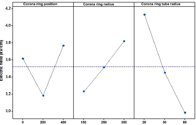
4.1. Introduction ... 4.1 4.2. Optimization structure of the Corona rings based on BAT algorithm ... 4.1 4.2.1. Problem formulation ... 4.1 4.3. Main effect plots and interactions effect of corona ring parameters ... 4.4 4.4. Implementation of the bat algorithm in designed corona ring ... 4.6
iii
4.6. Potential and Electric field distribution analysis ... 4.10 4.7. Conclusion ... 4.13
Chapter 05
Characterization and Improvement of porcelain
insulator
5.1. Introduction ... 5.1 5.2. Development of new porcelain insulator based on economic raw materials ... 5.2 5.3. Experimental analysis ... 5.2 5.3.1. Materials and methods ... 5.2 5.3.2.Characterization ... 5.8 5.4. Electrical performance of porcelain coated with TiO2 thin film... 5.24 5.4.1. Introduction ... 5.24 5.4.2. Importance of high voltage insulator's coating ... 5.24 5.4.3. Experimental procedure ... 5.25 5.4.4. Coating evaluation... 5.26 5.4.5. Electrical tests and results ... 5.29 5.4.6. E-field distribution and current density analysis ... 5.32 5.5. Conclusion ………..………5.36
Chapter 06
General Conclusions
6.1. Conclusions ... 6.1 6.2. Recommandations ... 6.2Bibliographic References
iv
List of figures
Figure 2. 1 Classification of power line insulators ... 2.2 Figure 2. 2 Porcelain insulator structure ... 2.4 Figure 2. 3 Radial cracking due to cement growth on porcelain insulators. ... 2.5 Figure 2. 4 Corroded pin in porcelain insulator ... 2.6 Figure 2. 5 Composite insulator structure... 2.8 Figure 2. 6 Degradation of composite insulator ... 2.10 Figure 2. 7 Corona discharge ... 2.11 Figure 2. 8 Evolution of the use of composite insulators in Algeria according to GRTE…... ... 2.16 Figure 2.9 Evolution of the installation of polymer insulator chains with respect to the total length of the network ... 2.16
Figure 3. 1 Insulator string equipped with corona rings 3.3 Figure 3. 2 Model of composite insulator and corona ring... 3.5
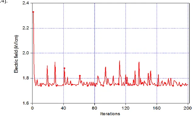
Figure 3. 3 A bat use echolocation to determine prey. ... 3.7 Figure 3. 4 Loudness (A) ... 3.9 Figure 3. 5 Pulse Emission Rate (r) ... 3.9 Figure 3. 6 Flowchart of Bat Algorithm ... 3.13 Figure 3. 7 Bat algorithm applications ... 3.14 Figure 3. 8 Flow diagram of electric field optimization for polymeric insulator ... 3.20 Figure 4. .1 Electric potential distribution without corona ring. 4.2 Figure 4. 2 Main effect plots of corona ring parameters H, R and Dr on the maximum value of E-field. ... 4.5 Figure 4. 3 Interaction effect plots of corona ring parameters H, R and Dr on the maximum E-field ... 4.5 Figure 4. 4 Convergence of objective function during the optimization model. ... 4.6 Figure 4. 5 Maximum electric field as a function of applied voltage. ... 4.8 Figure 4. 6 E-field variation along the insulator length with and without corona ring. .... 4.9 Figure 4. 7 Electric potential along the studied composite insulator. ... 4.9
v
insulator in the case without Corona ring. ... 4.11 Figure 4. 9 (a): Electrical field distribution,(b):equipotential contours around composite insulator in case with Corona ring ... 4.12 Figure 5. 1 samples sintered at different temperatures for 2 h 5.3 Figure 5. 2 Bruker diffractometer ...5.5 Figure 5. 3 spectroscopy (FTIR) Perkin Elmer 700 type ...5.6 Figure 5. 4 Setaram DTA 92 thermal analysis system...5.7 Figure 5. 5 Components of scanning electron microscopy (SEM). ...5.8 Figure 5. 6 XRD patterns of samples sintered at different temperatures for 2 h (a) N00, (b) G10, (c) G20 and (d) G30 ... 5.10 Figure 5. 7 FT-IR spectra of the samples sintered at 1100°C for 2 h ... 5.11 Figure 5. 8 DTA curves for samples mixtures during heating. ... 5.12 Figure 5. 9 Bulk density and Open porosity of the samples sintered at different temperatures ... 5.14 Figure 5. 10 (a): Shrinkage and (b): Water absorption of the samples sintered at different temperatures ... 5.16 Figure 5. 11 SEM micrographs of the samples sintered at1100°C for 2h :(a) G00, (b) G10,(c) G20,and (d) G30 ... 5.18 Figure 5. 12 Experimental set-up for measurement of mechanical proprieties ... 5.19 Figure 5.13 Vickers micro-hardness versus the sintering temperatures for samples containing N00, G10, G20 and G30 ... 5.19 Figure 5. 14 Precision impedance analyzers ... 5.21 Figure 5. 15 Dielectric constant ('), (b): Dielectric loss factor ('') versus frequency (MHz) ... 5.22 Figure 5. 16 Dielectric loss tangent (tan δ) versus frequency (MHz). ... 5.23 Figure 5. 17 Phase angle (°) versus frequency (MHz). ... 5.24 Figure 5. 18 Gwyddion GUI (Graphical User Interface) with AFM Data ... 5.27 Figure 5. 19 3D and 2 D image profiles of (a) uncoated sample and (b) coated sample with TiO2 film. ... 5.28 Figure 5. 20 Micro-Raman spectra of TiO2 of the surface of coated insulator. ... 5.29 Figure 5. 21 Overall view of Experimental setup. ... 5.30
vi
Figure 5. 22 Studied insulator model. ... 5.30 Figure 5. 23 Leakage current as function of applied voltage for coating and un-coated samples at (a) positive polarity (b) negative polarity. ... 5.32 Figure 5. 24 Results of COMSOL simulations of coated sample (a) E-field distribution and (b) electric potential ... 5.33 Figure 5. 25 Results of COMSOL simulations of un-coated sample (a) E-field distribution and (b) electric potential. ... 5.34 Figure 5. 26 E-field (a) and current density (b) as function of applied voltage. ... 5.36
vii
List of tables
Table 3. 1 Design parameters of studied composite insulator in mm. ...3.4 Table 4. 1 Corona ring parameters and their levels ...4.3 Table 4. 2 Computational results. ...4.3 Table 4. 3 Optimized CR Parameters Values ...4.7 Table 4. 4 Comparison between PSO and BA ... 4.10 Table 5. 1 Chemical compositions of the starting raw materials, mass (%) ...5.2 Table 5. 2 Percentage of additive material of samples, mass (%) ...5.3 Table 5. 3 Chemical compositions of all samples, mass (%) ... 5.13
viii
List of abbreviations
HV High Voltage
CR Corona Ring
GRTE Société Algérienne de Gestion du Réseau de Transport
de l’Electricité
FEM Finite Element Method 2D/3D Two/three Dimensional
BA Bat Agorithm
PSO Particle Swarm Optimization GA Genetic Algorithm
NO Neuro Optimizer
BSO Bee Swarm Optimization ANOVA Analysis of variance
OA Ortoganal Array
EPRI Electric Power Research Institute AC Alternating Current
DC Direct Current XRD X-Rays Diffraction
FT-IR Fourier-Transform infrared spectroscopy DTA Differential Thermal Analysis
SEM Scanning Electron Microscope AFM Atomic Force Microscopy
UV Ultra Violet
ix
List of symbols
mm Millimeter cm Centimeter m MeterH Corona ring height
Dr Corona ring tube diameter
R Corona ring radius
E Electric Field F2 s Coefficient of determination second kV Kilovolt mg Milligram G Glass N No glass MHz Megahertz kHz Kilohertz ' Dielectric Constant
" Dielectric loss factor
tng Loss tangent
Angle phase
Chapter 01
1 p.1.
General Introduction
1.1. BackgroundIn recent years, electricity has become one of the most important necessities in human life and extra high voltage power lines have been widely used to transmit the electric energy from the power stations to the end users. Insulators are among the key devices of the electric power transmission systems. They play a significant role in maintaining the reliability of the network. They are used to support, separate and contain conductors at high voltage. The insulators need to withstand not only regular voltages and over voltages, such as lightning, but also various environmental stresses such as rain, snow and pollution.
Insulators are made from dielectric materials such as glass, ceramic and composite materials. An insulator ideally is a substance which does not allow electric charge to flow through it and has no effect on the electric fields [1.1]. Therefore, dielectric materials which have high electric resistance and dielectric constants are used as an insulator. Starting with simple glass and porcelain insulators, it has rapidly developed since early of the century. These types of insulators can be considered as classic insulators and may put into the same category called as ceramic insulators. From research and service experience [1.2], they are reliable and cost effective for major outdoor installations. Although porcelain and glass insulators have good performance over the years, their main disadvantages are due to their bulky size which make them difficult to install in remote area, vulnerable to vandalism and most importantly is their poor performance in polluted environment. The modern style of polymeric outdoor insulators was introduced to replace ceramic insulators. The reason of this replacement was not a failure of ceramic insulators but
2 p.1.
During recent decades, polymer insulators have been introduced and widely used due to their better pollution performance. Insulators made of polymer materials are often called composite or non-ceramic insulators. They are mostly preferred because of their superior insulation performance. The most important factor that determines the physical dimensions of outdoor insulators is their performance under pollution conditions. Depending on the pollution severity and the wetting conditions of the site, outdoor insulators need to have sufficient surface leakage length to ensure that dry band formation and surface arcing is minimized.
Pollution flashover is one of the main problems that endanger the reliability of an electric power system. The presence of contamination on the insulator surface, combined with highly humid and wet conditions such as fog, dew or rain, is particularly responsible for many insulator pollution flashovers [1.3]. With higher and higher voltages, the problem of insulator pollution flashover increases and the penalties increase sharply due to the damage to the equipment. Therefore, more and more attention must be paid to improve the pollution performance of insulators. Reliability of the insulator is the most important property that must be taken into consideration whether it is a polymeric (composite) insulator or ceramic insulator. The good insulator should offer optimum electrical and mechanical strengths [1.4].
1.2. Problem statement
Most of the insulators being used nowadays are of the porcelain and glass insulators considering their well known field performance. However, there is favorable improvement in the use of non-ceramic insulators which have shown advantages compared to ceramic and glass insulators such as low weight construction, good performance in contaminated environments and easy handling. At higher voltages, electric fields can be high enough to cause surface flashover on porcelain/glass insulator, in case of polymeric type insulator damage to the insulator sheath due to the corona discharge.
3 p.1.
include many forms of precipitation, UV radiation and pollution. The voltage and electric field near conductors is much higher than other area of the insulator, which may lead to corona discharge and even flashover. The study of electric field on polymeric insulator when subjected to high voltage provides an important insight to improve the performance of the insulator. The design of a post insulator plays an important role in the insulator's performance. The performance and reliability of insulators may improve with the continuous improvement in the design. Several researchers have focused on the electric field optimal distribution along non- ceramic insulators string in order to reduce corona degradation. In addition, different techniques and insulators materials are developed. Among them, the installation of conventional corona rings. There are no specific standards for the design and placement of corona rings. Each manufacturer makes their own recommendations for the use of corona rings.
On the other hand, porcelain and glass insulators have outstanding insulating properties and weather resistance. However, they are lack in terms of their bulky size which becomes more difficult to install in remote area, vulnerable to vandalism. Moreover, their performances in polluted area are poor. This is due to its hydrophilic properties which enable water to easily form a continuous conductive film along the creepage path. This formation has encouraged the flashover and could cause the failure in power transmission lines.
In order to improve porcelain insulator performance, coatings were used to mitigate surface leakage current, surface discharges and reduce flashover occurrence on existing and installed porcelain insulators.
Optimized design of corona ring of the insulator and coatings are needed to ensure that the insulator can perform better and can provide longer service.
4 p.1.
1.3. Objectives
The reliability of the insulator is the most important property that must take into consideration whether it is a ceramic insulator or polymeric insulator. The performance and reliability of insulators may improve with the continuous improvement in the design.The study of electric field on insulators when subject to high voltage provides an important insight to improve the performance of the insulator. The overall works of the project will stress on the optimization of the electric fields around the composite insulator and assess the performance of coating used to minimize leakage current on a new prepared porcelain insulator.
The principal aims of this research work are as follows:
1. To identify the optimum corona ring location installation to improve the electric field around the composite insulator.
2. To examine the effectiveness of a new developed nature-inspired optimization approache that links the electric field strength to the corona ring structure parameters.
3. To simulate and analyse electric field distribution around composite insulators.
4. To develop porcelain from locally available raw materials.
5. To improve the mechanical and dielectric properties of the porcelain insulator.
6. To evaluate the effect of coating on the performance of the prepared porcelain by comparing its leakage current suppression and its flashover voltage performance in comparison with non coated porcelain.
In order to achieve these aims, it was required to use computer techniques to evaluate the electric field and leakage current:
COMSOL MULTIPHYSICS MINITAB
5 p.1. The results of this project show that:
The design parameters (corona ring height, corona ring radius and corona ring tube diameter) can be successfully optimized using Bat Algorithm; Maximum electric field on the live end side is importantly reduced around
the composite insulator below the corona threshold;
by glass addition, mechanical and dielectric properties of porcelain prepared at low temperature are improved;
When applied to the porcelain insulator, coating minimized the leakage current over its surface.
1.5. Thesis Organization
The thesis contains six chapters.
Chapter 1 mainly focuses on the background of the project which is the problems faced by polymer insulators and the objectives that driven this project.
Chapter 2 provides a general overview of different outdoor insulators along with their role in the power system networks. Further, the factors accelerating insulation degradation for insulators either ceramic or non ceramic insulators are reviewed. The objectives of the research are presented.
This chapter providing also a review of the literature related to the work concept and the previous works by other researchers.
Chapter 3 reviews the influence of electric field on insulator performance and the techniques to optimize the electric field. The experimental methods, bat algorithm and Finite element method which are employed for insulator modeling to determine electric potential and field distribution along the non-ceramic insulator. Also, a model of polymer insulators is used to study the effect of optimization techniques employed.
6 p.1.
Chapter 4 discusses the results of and analysis. One of the factors governing the electrical performance of polymeric insulator is characterized by its field distribution along their length. By improving the electric field distribution, it will help in enhancing their long term performance of insulator.
Chapter 5 discusses the possibility of developing porcelain using locally economic raw materials and studies the effect of coating on its electrical properties.
Chapter 6: presents the conclusions based on the findings from this study and outlines some recommendations for future investigations.
Chapter 02
High voltage insulators:
A literature review
1 p.2.
Chapter 02
High voltage insulators: A literature review
2.1. Introduction
The transport of electrical energy requires the use of high voltage lines. Overhead transmission lines are responsible for delivering electric power from generators to industrial and residential customers. The outdoor insulation is an important component of an electric power system. High voltage insulator plays an important role by serving two important functions [2.1]:
They isolate the conductor electrically from the grounded tower structure and
They serve as mechanical support for the conductor.
Nowadays insulators adopted for transmission/distribution are made of ceramic, glass or polymeric type. Porcelain and glass insulators have been used for a long time and there is considerable experience in manufacturing, installation and their field performance is well known. Composite insulator represents the last acquisition in the field of outdoor insulation; their use begun recently and knows an explosive development in the last years. Figure 2.1 shows the classification of the main types of insulators. Insulators are able to handle electrical and mechanical stresses when the line is energized. Most of the insulators have outdoor applications where they are subjected to environmental conditions such as moisture, high temperature, contamination, and icing. To choose the right type of insulator before the installation, the environmental conditions of the site have to be studied.
The aim of this chapter is to present both the advantages and disadvantages of each of porcelain and composite insulator and also focuses on the problems faced by these outdoor insulators. A review of the literature related to the work concept and the previous works by other researchers is presented.
2 p.2. H v in su la to rs C er am ic in su la to rs Po ly m er ic in su la to rs C om po si te in su la to rs : F ib re gl as s ro d w ith po ly m er ic s he d C as t c yc lo al ph at ic ep ox y re si n in su la to rs E PD M ru bb er Si lic on ru bb er G la ss Po rc el ai n B uc hi ng a nd ho llo w c or e in su la to rs Po st ty pe a nd lin e po st in su la to rs Pi n ty pe in su la to rs L on gr od in su la to rs C ap a nd P in in su la to rs
3 p.2.
2.2. Ceramic insulators
Ceramic insulators have been in use for more than 100 years [2.2]. They have proven to give excellent service history backed by years of manufacturing experience from reputable firms. The basic components used to make the ceramic insulator are clay, fine sand quartz and feldspar.The design and manufacturing of the ceramic insulators are being researched and improved in order to carter the needs of today’s power distribution and transmission system. However, limitations are given on their sheds design to meet the surface electrical leakage distance needed for higher voltage transmission. Ceramic insulators present a high mechanical strength; they provide excellent resistance to material degradation cause by electrical stress and discharge activities. They demonstrated also a proven track record in various aspects of the insulation performance, particularly ageing and lifespan. Ceramic insulators can be divided into two types namely porcelain and glass which give a little difference regarding to their cost and performance.The design and manufacturing of the ceramic insulators are being researched and improved in order to carter the needs of today’s power distribution and transmission system. However, limitations are given on their sheds design to meet the surface electrical leakage distance needed for higher voltage transmission. To smooth the surface of the insulator, glazing is used apart from increasing the mechanical strength and improving the surface’s hydrophobicity[2.3].
2.2.1. Porcelain insulator
Earlier insulators are made from high quality glazed porcelain and pre-stressed or toughened glass. They are reliable and cost effective for major outdoor insulations. Porcelain insulators have a long journey of history. Initially, it has been used in the telegraph line. It has been in the market since 1910. A considerate number of these insulators are now in service in Algeria. They are by far the most commonly used outdoor insulator in service. The market of glass and porcelain insulators is still dynamic at the moment, with all the disadvantages related to their mass, the assembly and installation costs, and the fragility to mechanical stresses or vandalism. Figure 2.2 shows the structure of porcelain insulator.
4 p.2.
Figure 2. 2 Porcelain insulator structure
The different insulator configurations are:
Cap and pin insulator
Station post insulators
Transformer and circuit breaker bushings
The large lifetime was the main reason for maintaining these types of insulators in operation, and, in certain cases, they represents the reliable solution. The weight of porcelain insulators used to be a problem, but the newer generations do not suffer from the weight issue anymore [2.4].
2.2.1.1. Mechanical and electrical performance of porcelain
Electrical properties of insulators come from the dielectric that they are made of. to study the electrical properties of porcelain insulators, dielectric properties of porcelain should be studied. There are two dielectric property measures; volume dielectric property and surface dielectric property [2.5]. The mechanical performance of insulators on the overhead transmission lines is as important as the electrical performance. These properties such as internal attachment of the metal pins to the dielectric are mainly concerned during the manufacturing process.
5 p.2.
2.2.1.2. Failure of traditional porcelain
Porcelain insulators can fail due to a variety of reasons. Prior to the installation, some insulators might get physically damaged during shipping and transportation. Vandalism is another reason of porcelain insulators failure. It suffers from having hydrophilic surface properties, which means that water can easily form a continuous conductive film along the creepage path, thus allowing high surface leakage currents to flow on their wetted surfaces. Such currents cause dry bands at areas of high current density and lower wetting rates, which eventually cause surface arcing and frequently complete flashover of the insulator. Poor manufacturing and low quality control are two other reasons of porcelain insulators failures.
2.2.2.2.1. Radial Cracking
This type of failure has been attributed to cement growth phenomenon as depicted in figure2.3. Cement can absorb moisture during wet conditions, thus escalating the expansion process. Such radial cracking of porcelain disks can eventually result in internal puncture. There are no reliable statistics regarding the incidence of this type of failure but it is widely published that failure rates of porcelain insulators due to cement growth problems are generally associated with specific production batches [2.6].
6 p.2.
Figure 2. 4 Corroded pin in porcelain insulator
Corona discharge can occur as a result of inappropriate electric stress grading at the cap of the insulator near the line end of a string of insulators. The metallic cap subsequently becomes exposed to corrosion as the discharge slowly degrades the protective galvanizing layer. Leakage current may also flow on the surface of the insulator during contamination and wet atmospheric conditions, which create a salt solution on the surface. Pin corrosion produced by electrolytic action can weaken the mechanical and cross-sectional strength of the pin. Damage of this sort can lead to an event as serious as conductor dropping. Figure 2.4 is an example of hardware exhibiting a very high degree of corrosion.
2.2.2.2.3. Insulator contamination
Under humid and moist conditions, surface contamination can cause flashover, which leads to system outages. Dust, rubber particles, sand, industrial pollution, and salt from the sea are some of the primary sources of insulator surface contamination. The deposition of contaminating particles is dependent on a number of factors, such as the speed and direction of the wind, the insulator type, and the orientation of the transmission line. Although, rain and heavy winds can wash away dust accumulated on insulators’ surface; the dust can still be accumulated on the bottom ribs. The
7 p.2.
orientation of the insulator string also influences the amount of contamination. Vertically oriented insulators, also known as an information, are prone to greater contamination than are V-shaped and horizontally oriented insulators. During moist conditions, the surface becomes highly conductive and the magnitude of the leakage current increases [2.7]. Dry band arcing that leads to flashover is the main problem under heavy contamination conditions [2.8]. Equivalent salt deposit density (ESSD) and non-soluble deposit density (NSSD) are the factors used for quantifying the level of contamination. ESSD is the amount of sodium chloride that, when dissolved, provides the same conductance as that of the natural deposit removed from the surface of the insulator divided by the area of that surface. NSSD is the amount of non-soluble residue removed from a given surface of the insulator divided by the area of that surface
2.3. Composite insulators
During recent decades, polymer insulators have been introduced and widely used at distribution voltage levels due to their better pollution performance. Composite insulators or known as non-ceramic insulators are widely used to replace porcelain and glass insulators in transmission lines. They were introduced in 1960’s and start to be installed in United States in 1970’s and since then, they become major option for utility companies around the world. Non ceramic insulators are usually made up of silic one rubber, Poly-Tetra -Fluoro-Ethane (PTFE) or Ethyl Propylene Diene Monomer (EPDM) rubber.
Figure 2.5 shows the structure of polymeric insulators with all three components flanges crimped to a fibre reinforce rod (FRP) encapsulated within weather shed polymeric housing.
8 p.2.
Figure 2. 5. Composite insulator structure
Composite Insulators consist of three parts :
Steel/aluminium end fitting terminals to support mechanical loads on conductors,
Fiber reinforced rod (FRP) core to carry mechanical load and insulation between two terminals,
Polymeric weather shed housing to protect the FRP rod against environmental influences, external pollution and humidity..
With the improvements in design and manufacturing, polymeric insulator becomes more attractive to the utility companies around the world to use it. The developments of new materials continue to grow with a number of new insulating materials that have been developed.
2.3.1. Advantages of composite insulator
Composite insulators become popular due to various advantages offered. Polymeric outdoor insulators made of polymeric material, especially silicone rubber, exhibit excellent electrical performances under moderate to heavily polluted environments [2.9]. In a wet atmosphere, water tends to bead up on the polymeric surface, thus reducing the leakage current and the probability of dry band formation, which
FRP core Silicon rubber shed Silicon rubber Sheath Hot-dip galvanized forged steel
9 p.2.
consequently results in reduced flashover voltages. Interestingly, this property can also be transferred to an overlying pollution layer [2.10] enabling improved pollution performance for insulation systems in highly contaminated regions such as coastal and industrial areas. Even though silicone housing can temporarily lose its hydrophobicity under severe conditions, the materials have been reported [2.11, 2.12] to be able to regain hydrophobicity after a sufficient resting period with the absence of discharge activity. Polymeric insulators offer significant weight reduction compared to the corresponding ceramic insulation systems [2.13]. There is less need for strong heavy support and cranes for installation, which results in easier handling and substantial savings in overall installation, operation and maintenance costs. In addition, voltage up rating and compact transmission tower design for Ultra-High Voltage (UHV) distribution networks can be practically realized with polymeric insulators. Polymeric insulators have a high mechanical strength to weight ratio that allows for longer spans and less expensive tower structures. They provide improved mechanical strength under bending, deflection and compression stress. It has been reported [2.14-2.16] that polymeric insulators passed mechanical tests under extreme conditions without any permanent damage. Insulation housing with elastic properties also helps to prevent the risk of breakage during transportation or vandalism from gunshots that could lead to cascading failure as was experienced with ceramic insulators. In addition, complex weather shed designs are feasible and easily moulded using polymeric composite material.
2.3.2. Degradation of composite insulator
Despite the abovementioned advantages, polymeric outdoor insulators however suffer from a problem of material deterioration as shown in figure 2.6, known as ageing. This is primarily due to concurrent stresses; environmental, electrical and mechanical stresses encountered in diverse range of service conditions [2.12].
10 p.2.
Figure 2. 6 Degradation of composite insulator
2.3.2.1 Electrical stress
The electric field distribution is not uniform along high voltage insulator where the highest field regions are at the high voltage end terminals and core areas. Electric discharges in the form of corona, dry band arcing and flashover will occur due non-uniform and high fields on the insulator [2.17, 2.18].
2.3.2.1.1. Corona discharges
Corona is phenomenon that has the capability for degrading insulators, and can cause systems to fail. It is also known as partial discharge where type of localized emission resulting from transient gaseous ionization in an insulation system when the voltage stresses or voltage gradient exceeds its critical value. There are three types of corona which are plume, brush and glow. Plume is the most spectacular corona and it is called as so because of its general resemblance to a plume. It also has audible manifestations which are rather intense snapping and hissing sound. Brush corona is a streamer projecting radially from the conductor. The audible manifestation that is associated with brush corona is generally a continuous background type of hissing or frying sound. The glow corona is a very faint, weak light which appears to hug the conductor‟s surface and there is generally no sound that is associated with it.
11 p.2.
Corona discharges occur at the insulator surface when the electric field gradients on the surface exceed the air breakdown strength. Corona formation is dependent upon atmospheric conditions such as air breakdown, humidity and insulator geometry. Corona cause radio and TV interference, noise, ozone, and energy loss. Corona accelerates the polymer aging by producing ozone and ultra-violet light [2.19, 2.20]. The effects of corona in transmission lines can be summarized as below:
a violet glow is observed around the conductor. produces a hissing noise,
produces ozone which can be readily detected by its odor,
the glow is maximum over rough and dirty surfaces of the conductor, accompanied by a power loss
charging current under corona condition increases because the corona induces harmonic currents.
Figure 2.7 shows corona discharge activity.
12 p.2.
Active discharge activities from corona, water droplets and dry band arcing generate considerable thermal heating that cause further drying on the insulator surface. Electric discharges that are short at the beginning gradually elongate as the dry regions widen. Under favourable conditions, successive discharges may extend over multiple dry bands and join with other electric discharges that can eventually lead to a complete flashover [2.21]. In the event of prolonged wetting and heavy rain, polymeric weather sheds can be bridged by the water stream. The role of the creepage path along the insulator surface in limiting leakage current in this case is not effective. Water cascading promotes inter-shed arcing, and can easily lead to insulator flashover even at lower pollution severity. In addition, the flashover can occur at much lower voltage levels than the rated value. Polymeric insulators with an alternating shed design can be a good practice to minimise the probability of water bridging the weather sheds [2.22].
2.3.2.2. Environmental Stress
2.3.2.2.1. Pollution
Environmental pollution is one of the major threats to polymeric outdoor insulation systems. Depending on the location and the surrounding area, insulators encounter different types of pollutants: sand and soil elements in desert and mining areas, metallic and chemical substances in industrial and agricultural lands, and salt particles in coastal regions. Deposits of these airborne particles gradually form a solid pollution layer on the insulator surface, which has a significant effect on both short and long-term performance of the insulation system. Electric field distribution is highly distorted by a non-uniform pollution layer on the insulator surface [2.23]. This contributes to localised field enhancement which could trigger corona and random partial discharges over the polymeric surface. In the presence of moisture, soluble contaminants dissolve in water establishing a conductive pollution film that allows the flow of leakage current along the creepage distance, increasing the risk of damaging dry band discharges. In some cases, the insulator may also be subjected to conductive
13 p.2.
moisture sources such as salt water, industrial acid fog, chemical mist and fertilizers, crop spraying and acid rain. These electrolyte-type pollutants can cause instantaneous leakage current and trigger flashover voltage even without the accumulation of pollution on the insulator surface [2.24, 2.25].
2.3.2.2.2. Ultra-violet radiation
Polymeric insulators installed for outdoor applications are open to ultra violet (UV) radiation from sunlight. The surfaces are attacked by UV photons that release substantial energy to break crosslink chains or individual molecules within the base matrix [2.26]. Polymeric compounds for high voltage insulation housing contain impurities such as vulcanizing agents, catalysts and fillers that are vulnerable to UV radiation due to their weak molecular bond. The presence of these additives weakens the strong carbon-based polymer i.e. C-C, C-H and Si-O bonds, thereby reducing the resistance of polymeric weather sheds housing to UV exposure. Thermal and photooxidation cause chain scissions that destroy hydrophobicity and lead to surface cracking and degradation of the polymeric material [2.27]. The condition is exacerbated in high temperature regions such as deserts. From service experience reported in [2.28], polymeric surfaces that faced the sun appeared to be less hydrophobic and showed chalking and discoloration compared to those on the shaded side.
2.3.2.3.Mechanical Stress
An important function of the line insulator is to transfer mechanical support from the transmission tower to hold the heavy overhead conductor well in the air. Line insulators experience vertical load (tensile and compression stress) or cantilever/transverse load (bending stress) depending on system configuration and tower structure. Suspension insulators, when first installed on transmission towers, for example, encounter constant axial stress by the loading of bundle cables in which the weight could reach up to several tonnes for UHV transmission systems. Over time, continuous strain could gradually deteriorate and weaken the joint between the core
14 p.2.
polymeric insulators. Extra mechanical stress may also develop when strong winds move the line, causing oscillation. The consequent vibrations can cause the formation of fissures at the joint interface between the core and the metal flanges. In some cold-climate countries, ice accretion on both the conductor and weather sheds housing could generate additional loading stress on the polymeric insulator. In hot desert regions, the average temperature can easily reach 40°C during the day, and drop below 10°C at night. This considerable change in ambient temperature results in a cyclic process of thermal expansion and shrinkage that can loosen the connection at the core-end fitting interface, affecting the mechanical strength of the polymeric insulators. In the face of these problems, insulation materials must have some specific properties. Such as,
1. It must be mechanically strong, so that to carry tension and weight of the conductors.
2. The dielectric strength must be very high, so that to withstand the high voltage stress.
3. The insulation resistance must be high, so that to prevent the leakage current to the earth.
4. It must be free from unwanted impurities and should not be porous. 5. It should be non-hydroscopic.
6. Its physical and electrical properties must be less affected due to change in temperature.
15 p.2.
Table 2. 1 Advantages of composite materials (SIR) over ceramics
2.4. The evolution of the use composite insulators according to GRTE
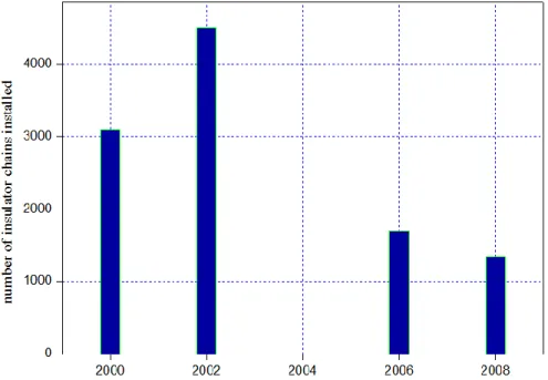
In Algeria, Composite insulators introduced since 2000. They are used in 60 and 220 kV transmission line. Figures 2.8 and 2.9 represent the evolution of the use composite insulators and evolution of the installation of polymeric insulator chains with respect to the total length of the network in Algeria, respectively. It is noted that the percentage of the installation of polymeric chains is very low as shown in figure 2.9 .it begin by installing 330 insulating chains. This number is increased 4400 in 2002. Due to vandalism acts, the installation of composite insulator is decreased in 2006 and 2007 before it started to rise again in 2008 by installing 3801 insulator chains.
A high voltage level is introduced by SONELGAZ (the Algerian society of electricity and gaz) due to the increasing demand for a continuous electric power supply and high quality service. For this, M. Bouhaouche et al. [2.29] proposed integring composite insulators in the 400 kV transmission lines which are recently begin in service with the objective of improving Electric field distribution. Reported results confirm that to use
Advantages of composite materials (SIR) over ceramics
Criteria Ceramic Composite (SIR)
weight Heavy Leger (90% Lighter)
transport Expensive and risky of breakage Resistance to shocks
installation Risky, expensive, need for more labor Easy and economic
vandalism Susceptible Very resistant
breaking behavior Fragile shock and vibration / brittle
fracture Insensitive to shock
resistance to
electric arcs low High
erosion resistance Very low High
dielectric strength lower Exellente
Pollution behavior Facilitated affected Not affected
hydrophobicity
Hydrophilic-formation of water film on the surface that increases the risk of electric arc
Hydrophobic- formation of water droplet
contamination Presence of salute, sand, salt and snow Absente
maintenance Cleaning No maintenance
conception Limited flexibility design - wider and
heavier structure
Gain weight, size and cost
16 p.2.
transmission in Algeria. Experimental test under dry, clean and uniformity polluted surface conditions show also that the maximum electric field gets its minimum value when composite is used compared the glass one.
Figure 2. 8 Evolution of the use of composite insulators in Algeria according to
GRTE
Figure 2. 9 Evolution of the installation of polymer insulator chains with respect to
17 p.2.
2.5. Literature survey
The following paragraphs show some of the project referred in completing this thesis. Yang Qing et al. proposed a new optimization Method on Electric Field Distribution of Composite Insulator [2.30]. The results show that by his proposed method, the electric field distribution near the ends of composite insulators is significantly reduced, which can prevent the partial discharge and the aging of the composite material.
W. Sima et al. studied the optimization of corona ring design for long-rod insulators using FEM based computational analysis [2.31]. This research presents a method to optimize the location and the dimensions of the corona ring for transmission line composite. The procedure used to optimize the corona ring design, which handles more than one parameter, has been verified with examples that have an analytical solution or known optimal values.
D. Cruz Dominguez used two electrical stress grading techniques for non-ceramic insulators. In both techniques some parameters were optimized for a 115 kV non ceramicinsulator with the objective of optimizing the electric field grading systems in non-ceramic insulators [2.32].
Edward Niedospial et al proposed a study about the application of corona and grading rings for composite insulators [2.33]. The addition of a corona ring to a polymer insulator will improve the insulators performance, but it must be the right ring used for the right reasons to realize the benefits.
E. Akbari et al. analyzed the effects of disc insulator type and corona ring on electric field and voltage distribution over 230-kv insulator string by numerical method [2.34]. According to the results, distribution of voltage and electric field over insulator strings without corona ring and the degree of improvement of voltage distribution using corona ring depends on insulator material and profile, as well as the corona ring configuration parameters.
18 p.2.
and potential distribution along insulator. He found that the usage of corona ring will significantly decrease the voltage percentage. That is, potential distribution will be more uniform with the help of corona ring. Furthermore, the maximum electric field strengths on the live end side will importantly decrease with the usage of corona ring. Moreover, the electric field on the corona ring surface can also change with the design parameters.
Zhao [2.36] studied the electric field and potential distribution along non-ceramic insulators. Results showed that the maximum electric field strength decreases when the length of the conductor increases; and the tower structure in the vicinity of the insulator and the diameter and the location of the grading ring are important in determining the maximum E-field.
S. M Braini investigate and assess on his thesis titled ―coatings for outdoor high voltage insulators‖ the performance of different coating materials used to minimize leakage current, reduce the heat and eliminate flashover in high voltage insulators that run in polluted environments. He found that with a nano-coating applied to the porcelain insulator, the surface becomes highly hydrophobic. It suppressed leakage current and reduced the energy dissipated over, the surface but the nano-coated insulator had a lower flashover voltage than an uncoated porcelain insulator having similar geometry. The nano-coated insulator lost its hydrophobicity showing a water film on its surface when exposed to fog application as seen through polluted wet tests [2.37].
2.6. Conclusion
This chapter allowed us to present the notions useful to the good conduct of this research project. We have discussed about the overview of benefits and limitations of polymeric and ceramic insulators also, a literature survey related to the work concept and the previous works by other researchers is presented.
Chapter 03
Optimization of Corona Ring Design
for Improved Electric Field
1 p.3.
Chapter 03
Optimization of Corona Ring Design for Improved
Electric Field Performance
3.1. Introduction
The performance of composite insulators depends on E-field distribution along the surface of insulators. It is essential to understand the E-field distribution along the length of insulator. The electric field distribution of non-ceramic insulator is different compared to porcelain insulators. Generally the electric field distribution of a non-ceramic long insulator is more nonlinear than that of a porcelain insulator. The reason is that there are no intermediate metal parts for a non-ceramic insulator.
The electric field strength on non-ceramic insulators needs to be controlled for the following reasons [3.1]:
• To prevent significant discharge activity on the surface material of non-ceramic insulators under both dry and wet conditions which may result in the degradation of the pollution performance of non-ceramic insulators.
• To avoid the internal discharge activity inside the fiberglass rod and the sheath rubber material that could result in mechanical or electrical failure of non-ceramic insulators.
• To prevent corona activity from the metal hardware or the non-ceramic insulator, which may cause radio interference and acoustic emissions.
2 p.3.
3.2. Field Optimization techniques
Surface discharge process and continuous corona on the insulator contribute to generate degradation. It causes the reduction of the long term performance of composite insulators [3.2].To minimize this phenomenon, many methods of optimizing electric field distribution on composite insulator are discussed, such as modifying insulator weather sheds profile, applying non-linear field grading material as insulator fillet, or by installing corona rings. The last one is discussed in many previous studies [2.33-2.36]. Each of these studies confirmed that the usage of corona ring in a composite insulator will significantly decrease the electric field distribution. Several studies have been carried out to optimize the design of the corona ring because there is no available standard for its design and placement.
3.2.1. Corona Ring Installation
The electric field (E-field) distribution along the insulator is an important factor which impacts the life expectancy as high E-field can result in a discharge activity which in-turn can damage the insulating material resulting in failure [3.3]. In order to prevent or reduce the discharge activity, it is important that the utilities ensure that the electric field distribution is managed to keep maximum recorded values below threshold levels. To this end, corona rings are applied. The function of the corona ring is to grade or disperse the electric field gradient, thus reducing the voltage stress on the rubber housing near the line end fitting. The corona ring can be attached to the composite insulator directly or as part of the hardware. When applied as part of the hardware, the grading device is commonly referred to as a Corona Shield [3.4]. Insulator strings (Figure3.1) are equipped with auxiliary apparatus to provide connections and to improve insulator string performance. Both the geometry and the design of these apparatus are dependent on the transmission voltage level and the insulator type.
3 p.3.
Figure 3. 1 Insulator string equipped with corona rings
Corona rings are the auxiliary fittings used with the insulator strings and can be used with any type of insulator. They improve the performance of insulator string in several ways:
- They reduce corona discharges on the terminals of the insulator string,
- They reduce the audible noise, radio interference (RI) and television interference (TVI) voltages,
- They can adjust the voltage distribution along the insulator string; reducing the maximum electric field strength [3.5].
The corona rings are also used for arc protection. For insulator flashovers, it is necessary to keep the power arc away from the insulator and to fix the root of the arc on the ring to avoid heating of the end fittings. Moreover, some testing experience has demonstrated that certain design of corona rings have a favorable effect of preventing dry band arcing near the end fittings of the composite insulators in polluted conditions [3.6].
In addition, corona rings can affect the AC, lightning impulse, switching impulse withstands/flashover levels of the insulator strings.
Many research works have been carried out to optimize the design of the corona ring because there is no available standard for its design and placement [3.7-3.9].
4 p.3.
In [3. 7, 3.8], particle swarm optimization (PSO) algorithm was used and a relationship between the maximum E-field and the geometrical parameters of the corona ring was established. A similar study was done in [3.9], in which the above relationship was modeled and optimized using the response surface methodology and reported results show the influence of the ring tube diameter on the E-field distribution. In [3.10], the authors evaluated the use of corona rings on 115 kV non-ceramic insulators to reduce the maximum electric field on its surface based on the geometry modifications. It is found that the tangential electric field can be reduced with the adequate geometry and relative permittivity value of the housing material. Diako et al. [3.11] have applied Neuro optimizer (NO) and genetic algorithm (GA) methods to study and compare the impact of distance and the size of the corona ring, on the magnitude and distribution of electrical potential across the polymer insulators.
In fact, there is many optimization problems related to design high voltage insulation used the meta-heuristic approaches to minimize different proposal mathematical models of the objective functions, in presence of various constraints. Based on a previous literature survey, and to the author’s knowledge, no work has been conducted to optimize corona ring design using Bat algorithm.
3.3. Insulator model
This chapter presents the proposed corona ring optimization for a composite insulator which consists of fiberglass rod and metal end fitting. The insulator profile is shown in Figure. 3.2. The numerical values of the basic parameters are listed in table 3.1, were P is the dry arcing distance, L is the creepage distance, d1/d2 is the sheds spacing, N1/N2 is the number of sheds, D1/D2 is the shed diameter and d is the rod diameter,
respectively. The insulator unit contains 25 large and 25 small sheds.
Table 3. 1 Design parameters of studied composite insulator in mm.
N0 P L d1/d2 N1/N2 D1/D2 D
5 p.3.
4.3and 7.2 respectively [3.9]. The composite insulator model as shown in Figure. 3.2 was created using COMSOL Multiphysics. In order to make the simulation faster without affecting results accuracy, insulator model is simplified into a two-dimensional (2D) problem. H 2R Dr D D2 D1 Triple Point d2 d1
Figure 3. 2 Model of composite insulator and corona ring.
3.4. Bat Algorithm
This section is discussing on how the work is carried out in order to obtain the aims of this project. We presented a general review on Bat algorithm. It is proposed to determine the optimal design of corona ring. A composite insulator is modeled using FEM to study the E-field distribution on its surface. The main and interaction effects of the corona ring parameters have been evaluated using the variance analysis technique using the MINITAB software in combination with COMSOL.
![Figure 2. 3 Radial cracking due to cement growth on porcelain insulators [2.6].](https://thumb-eu.123doks.com/thumbv2/123doknet/3403925.98592/31.892.246.656.770.1063/figure-radial-cracking-cement-growth-porcelain-insulators.webp)