i
Abstract
Nowadays, embedded s ystems a re more a nd more nu merous w hich s trongly i mpact energy conversion systems. The associated constraints are masses and losses reductions in order t o i mprove e nergy e fficiency i n t he c onversion chain. T his is the cas e i n t he aeronautics field where the concept of ″More Electric Aircraft″ now becomes a reality. Therefore, the permanent magnet synchronous machine becomes an excellent actuator due to its high power density, its low maintenance cost and its dynamic qualities.
When these machines are associated to carry out cooperative functions (for example, in flight surfaces) the embedded mass can still be reduced by sharing power electronics. It is precisely i n t his c ontext w here our w ork ha s b een de veloped, power r educed s tructures based i n p ower el ectronics, ab le t o f eed t wo or m ore el ectric m achines i n p arallel an d providing control laws to improve energy efficiency.
We h ave w orked m ore sp ecifically i n t he Predictive C ontrol of t wo S ynchronous Machines connected in parallel connected to a 2-Level 3-Phase Converter. These machines have identical characteristics and must follow the same speed profile with a load torque which can be different and, in any case, independent.
The predictive control approach leads us to consider the voltage inverter as a d evice with a f inite n umber o f co ntrol st ates. W e n eed t o select at each time i nstant the b est control s olution t o m inimize a c ost f unction. T his c ost f unction r elated t o one or t wo machines, i s co mposed o f a t erm representing t he qua lity of t he pr oduced t orque ( Iq current) and another which represents the quality of the conversion via produced losses (Id current).
This a pproach w orks n aturally in variable s witching f requency. T hus, t he doc ument considers d ifferent s tudied s olutions, s howing t he l imits of s uch a pproach bot h dynamically and in terms of losses. To improve this basic solution we develop an approach based on virtual vectors. These virtual vectors increase the control possibilities and lead to a co nstant switching f requency o peration t hrough a S VM modulation. T he r esearch algorithm of an optimum virtual vector is proposed and applied to a system composed by two l ow-power m achines. T he di fferent pr oposals a re v alidated through num erical simulation and consolidated by experimental results.
Key words:
• Multi-machine system • Open loop stability • Shared structures
• Permanent Magnet Synchronous Machines • Predictive control
iii
Résumé
De nos jours, les systèmes embarqués sont de plus en plus nombreux ce qui impacte fortement les systèmes de conversion de l’énergie. Les contraintes associées se t raduisent par une réduction des masses et des pertes afin d’améliorer l’efficacité énergétique de la chaine d e c onversion. C’est l e cas d ans l e d omaine de l ’aéronautique où l e c oncept ″d’avion plus électrique″ devient aujourd’hui une réalité. C’est ainsi que la machine synchrone à aimants permanents devient un a ctionneur d’excellence de par sa pui ssance massique importante, son faible coût de maintenance et ses qualités dynamiques.
Lorsque ces machines sont associées pour remplir des fonctions coopératives (surfaces de v ol p ar ex emple) on p eut encore réduire l a m asse em barquée en m utualisant l’électronique de puissance. C’est précisément dans ce cadre que se si tue notre travail, en proposant d es st ructures d ’alimentation réduites, à b ase d’électronique d e p uissance, permettant d’alimenter deux ou plusieurs machines électriques en parallèle et en proposant des lois de commande visant à améliorer le rendement énergétique.
Nous nous sommes intéressés plus particulièrement à la Commande Prédictive de deux Machines Synchrones alimentées en parallèle par un Onduleur de Tension Triphasé. Ces machines ont des caractéristiques identiques et doivent suivre un même profil de vitesse avec un couple de charge différent et en tout cas indépendant.
L’approche c ommande pr édictive nous c onduit à c onsidérer l ’onduleur de t ension comme un dispositif ayant un nombre fini d’états de commande. Nous devons sélectionner à chaque instant la meilleure solution de commande permettant de minimiser une fonction coût. C ette fonction c oût, r elative à une ou d eux m achines, e st c omposée d’ une pa rtie représentant la qualité du couple produit (courant IRqR) et d’une autre partie représentant la
qualité de la conversion via les pertes produites (courant IRdR).
Cette ap proche o père n aturellement à f réquence d e d écoupage v ariable. A insi l e document fait é tat d e d ifférentes s olutions étudiées m ontrant le s limites d ’une te lle approche t ant sur l e pl an dyna mique que s ur le pl an de s pe rtes. P our a méliorer c ette solution de base nous développons une approche basée sur l’utilisation de vecteurs virtuels. Ces v ecteurs v irtuels a ugmentent l es p ossibilités d e co mmande et co nduisent à u n fonctionnement à f réquence c onstante a u travers d’ une modulation de t ype S VM. L a recherche d ’un ve cteur vi rtuel opt imum e st proposée e t a ppliquée sur un di spositif composé de deux machines de faible puissance. Les différentes propositions sont validées par la voie de la simulation numérique et consolidées par des résultats expérimentaux.
Mots clés:
• Système multi-machines • Stabilité en boucle ouverte • Mutualisation
• Machine synchrone à aimants permanents • Commande prédictive
v
DEDICATION
This dissertation is dedicated to my late father, NGUYEN Xuan Ngoc, and to my mother, TRUONG Thi Quynh Mai, who always had confidence in
me and offered me encouragement and support in all my endeavors
It is also dedicated to my darling wife, THUONG Phuong Nga, and my lovely unborn child for their care, love, understanding, and patience
vii
Preface and Acknowledgements
The r esearch s tudy r eported in t his t hesis ha s be en pe rformed i n t he L aboratory o f Plasma and Conversion of Energy (LAPLACE), ENSEEIHT, INP Toulouse. The work has been c arried out i n t he period f rom A pril 2010 t o A pril 2 013 unde r t he s upervision of Professor INPT Maurice FADEL and Associate Professor INPT Ana LLOR.
To ach ieve t hese results, besides my ow n e fforts, i t i s impossible to l ack of t he assistance, very kind support as well as the encouragements of many people. I would like to thank all of them for their contribution in my work.
I wish to express my deep gratitude to my supervisors, Professor Maurice Fadel and Professor A na L lor, f or t he gui dance, e ncouragement a nd s upport du ring m y gr aduate study. T heir c reative t hinking, kno wledge a nd e xpertise were t he “ power s upply” a nd “feedback” of my conducted researches.
I would like to thank President of the University of Toulouse – Marie France Barthet, Professor INPT Maria DAVID for their administrative support,
I am also grateful to Dr. Damien Didart for his kind advices and discussions for the experiment in this thesis.
I wo uld l ike t o e xpress my a ppreciation t o t he members of t he t hesis de fense committee, P rofessor S antiago G ómez A rnaltes f rom U niversity o f Madrid, P rofessor Emmanuel Godoy from École Supérieure d’électricité (SUPELEC) for their interest in my research work and the time and effort in considering this thesis.
The USTH program is gratefully acknowledged for its financial support to this research study.
I w ould l ike t o t hank a ll of my c olleagues: C eline, J ulie, E tienne, T rung, H a, T hiet, Thinh … who always support, help and encourage me during the past time.
Toulouse, May 2013
Table of contents
9T Abstract9T ... i 9T Résumé9T ... iii 9T DEDICATION9T ... v 9TPreface and Acknowledgements9T ... vii
9T
Table of contents9T ... ix
9T
List of symbols9T ... xiii
9T
List of abbreviations9T ... xv
9T
General Introduction9T ... 1
9T
Chapter 1 PMSM with Multi-Machine Systems9T ... 5 1.1 Introduction ... 6 1.2 Evolution of permanent magnet synchronous machine (PMSM)... 7
9T
1.2.19T 9TSmall power applications of PMSM9T ... 8 9T
1.2.29T 9TMedium power applications of PMSM9T ... 9 9T
1.2.39T 9THigh power applications of PMSM9T ... 10 1.3 Multi-machine system in aeronautic field ... 11
9T
1.3.19T 9TThe idea of sharing structures9T... 11 9T
1.3.29T 9TFlight control systems9T... 12 9T
1.3.2.19T 9TIntroduction9T ... 12 9T
1.3.2.29T 9TElectromechanical actuators (EMAs)9T ... 14 9T
1.3.2.39T 9TShared structures9T ... 15 1.4 Typical structures of multi-machine system ... 16
9T
1.4.19T 9TClassical structure9T ... 16 9T
1.4.29T 9TPresentation of the shared structures9T ... 18 9T
1.4.2.19T 9TSharing common legs structure: n machines with 2n legs9T ... 18 9T
1.4.2.29T 9TSharing the midpoint structure: n machines and 2n legs9T ... 20 9T
1.4.2.39T 9TMixed structure: 3𝑛
2 legs for n machines9T ... 22
9T
1.4.2.49T 9TParallel structure: 3 legs for n machines9T ... 23 9T
1.4.2.59T 9TSome other structures9T ... 24 9T
1.5 Conclusions ... 26 9T
Chapter 2 Mono-Inverter Dual-Parallel PMSM drive system9T ... 27 2.1 Introduction ... 28 2.2 Generalities about PMSM drive system ... 29
9T 2.2.19T 9TPrinciple of operation of PMSM9T ... 30 9T 2.2.29T 9TModeling of PMSMs9T ... 31 9T 2.2.2.19T 9TElectromechanical description9T ... 31 9T
2.2.2.29T 9TContinuous model of PMSM in d-q reference frame9T ... 34 9T
2.2.39T 9TStability analysis of PMSM9T ... 36 9T
2.2.49T 9TA three-phase two-level voltage inverter9T ... 39 2.3 Control strategies for PMSM drive ... 39
9T
2.3.19T 9TField oriented control9T ... 40 9T
2.3.29T 9TDirect Torque Control (DTC)9T ... 41 9T
2.3.39T 9TDirect Predictive Torque Control (DPTC)9T ... 44 2.4 Control structure for Mono-inverter Dual-parallel PMSM system ... 46
9T
2.4.19T 9TMaster-slave structure9T ... 46 9T
2.4.1.19T 9TGeneral description9T ... 46 9T
2.4.1.29T 9TConsequence due to a load variation9T ... 47 9T
2.4.1.39T 9TThe choice of master machine9T ... 48 9T
2.4.1.49T 9TConclusions9T ... 52 9T
2.4.29T 9TDirect torque control (DTC) for mono-inverter dual-parallel PMSM9T ... 52 9T
2.4.2.19T 9TGeneral description9T ... 53 9T
2.4.2.29T 9TOptimal switching table for two machines9T ... 55 9T
2.4.2.39T 9TSimulation tests9T ... 61 2.5 Conclusions ... 64 9T
Chapter 3 Predictive Torque Control with Mono-Inverter Dual-Parallel PMSM9T ... 65 3.1 Introduction ... 66 3.2 PMSM under voltage supply mode ... 67
9T
3.2.19T 9TSteady state calculation9T ... 67 9T
3.2.29T 9TSmall deviation model9T ... 72 3.3 PTC for Mono-Inverter Dual-parallel PMSM ... 74
9T 3.3.19T 9TDescription9T ... 74 9T 3.3.29T 9TR-S-T discrete controller9T ... 75 9T 3.3.2.19T 9TIntroduction9T ... 75 9T
9T
3.3.39T 9TPredictive Torque Control9T ... 77
9T 3.3.3.19T 9TDiscrete model of considered system9T ... 78
9T 3.3.3.29T 9TCost function9T ... 81
9T 3.3.3.39T 9TPredictive control strategies9T ... 83
3.4 Direct Predictive Torque Control (DPTC) ... 84
9T 3.4.19T 9TPrinciple9T ... 85
9T 3.4.29T 9TSimulation results for DPTC9T ... 86
9T 3.4.39T 9TRelation between the ripple and the sampling time of DPTC9T ... 90
9T 3.4.49T 9TOptimization problem9T ... 91
9T 3.4.59T 9TConclusions9T ... 94
3.5 Predictive Torque Control – “Split and Seek” (PTC-SS) ... 95
9T 3.5.19T 9TPredictive model in (𝛼𝛽) frame:9T ... 96
9T 3.5.29T 9T“Split and Seek” approach9T ... 96
9T 3.5.2.19T 9TAngle seeking9T ... 97
9T 3.5.2.29T 9TMagnitude seeking9T ... 99
9T 3.5.39T 9TSimulation results for PTC-SS9T ... 101
9T 3.5.3.19T 9TA comparison with DPTC9T ... 101
3.6 Conclusions ... 105
9T Chapter 4 The experimental platform9T ... 107
4.1 General description ... 107
4.2 Motor coupling system ... 109
4.3 Power supply system ... 112
9T 4.3.19T 9TPower supply system9T ... 112
9T 4.3.29T 9TPower converter9T ... 113
4.4 Measurement and control system ... 113
9T 4.4.19T 9TMeasurement interfaces9T ... 113
9T 4.4.1.19T 9TCurrent measurement9T ... 113
9T 4.4.1.29T 9TMechanical position measurement9T ... 113
9T 4.4.1.39T 9TSpeed calculation9T ... 115 9T 4.4.29T 9TdSPACE system9T... 116 9T 4.4.2.19T 9TdSPACE DS1103 board9T ... 116 9T 4.4.2.29T 9TMATLAB/Simulink and Control-desk9T ... 116
4.5 Digital control implementation ... 117
9T 4.5.19T 9TSpeed controller9T ... 118
9T 4.5.29T 9TPredictive torque controller9T ... 118
4.6 Experiment’s results ... 119 9T
4.6.19T 9TTest with one machine9T ... 119 9T
4.6.29T 9TTest with two machines in parallel9T ... 122 9T
4.6.39T 9TTest with two machines in parallel under master/slave configuration9T .. 125 4.7 Conclusions ... 127 9T
Conclusions and Perspectives9T ... 129
9T
Bibliography9T ... 133
9T
Résumé en français9T ... 141
9T
Appendix A9T 9T"FMINCON" and SVM technique9T ... 167 A.1 Using FMINCON to solve the optimal problem: ... 168 A.2 Space vector modulation (SVM) ... 169
9T
A.2.19T 9TDetermine 𝑉𝛼, 𝑉𝛽, 𝑉𝑟𝑒𝑟 and angle 𝛼9T ... 170 9T
A.2.29T 9TDetermine time duration 𝑡1, 𝑡2 and 𝑡0/7 ... 170 9T
A.2.39T 9TDetermine the switching time of (𝑠𝐴, 𝑠𝐵, 𝑠𝐶) ... 171 9T
Appendix B9T 9TTechnical data of the experimental9T ... 175 B.1 The auto-transformer ... 176 B.2 The SEMIKRON device ... 176
9T B.2.19T 9TThe rectifier9T ... 176 9T B.2.29T 9TThe inverter9T ... 176 B.3 The PMSM ... 178 9T B.3.19T 9TThe motor9T ... 178 9T
B.3.29T 9TThe holding brake9T ... 178 9T B.3.39T 9TThe resolver9T ... 179 B.4 Mechanical properties ... 180 9T B.4.19T 9TLoad machine9T ... 180 9T
B.4.29T 9TThe SEC-AC-305 (Smart Electromotor Controller)9T ... 180 9T
B.4.39T 9TSpindle axes with recirculating ball bearing guide9T ... 183 B.5 Hardware part of the control ... 185
9T B.5.19T 9TDS1103 PPC Controller Board9T ... 185 9T B.5.29T 9TCurrent sensors9T ... 188 9T B.5.39T 9TLimit switches9T ... 190 B.6 The Human-Machine Interface ... 191 9T
List of figures9T ... 193
9T
List of symbols
𝜓𝑝 Permanent magnet flux (𝑊𝑏)
𝜓𝑠 Flux linkage of machine (𝑊𝑏)
𝜓𝛼 Flux linkage of machine in 𝛼-axis (𝑊𝑏)
𝜓𝛽 Flux linkage of machine in 𝛽-axis (𝑊𝑏)
𝜔𝑙 Mechanical speed of motor (𝑟𝑟𝑟. 𝑠−1)
𝜔𝑙1 Mechanical speed of motor 1 (𝑟𝑟𝑟. 𝑠−1)
𝜔𝑙2 Mechanical speed of motor 2 (𝑟𝑟𝑟. 𝑠−1)
𝜔𝑒 Electrical speed of motor (𝑟𝑟𝑟. 𝑠−1)
𝜔𝑒1 Electrical speed of motor 1 (𝑟𝑟𝑟. 𝑠−1)
𝜔𝑒2 Electrical speed of motor 2 (𝑟𝑟𝑟. 𝑠−1)
𝜔𝑟𝑒𝑟 Mechanical reference speed (𝑟𝑟𝑟. 𝑠−1)
𝜔𝑒_𝑠𝑙 Electrical speed of slave motor (𝑟𝑟𝑟. 𝑠−1)
𝜔𝑒_𝑙 Electrical speed of master motor (𝑟𝑟𝑟. 𝑠−1)
𝛼 Argument of the complex impedance Z of the stator PMSM (𝑟𝑟𝑟)
𝛿 Load angle (𝑟𝑟𝑟)
𝛿𝑠𝑙 Load angle of slave machine (𝑟𝑟𝑟)
𝛿𝑙 Load angle of master machine (𝑟𝑟𝑟)
𝜃𝑒 Electrical angle of poled flux (𝑟𝑟𝑟)
𝜃𝑙 Mechanical angle of rotor (𝑟𝑟𝑟)
(𝜃)0 Initial value of 𝜃 (𝑟𝑟𝑟)
𝑇𝑒 Electromagnetic torque generated by a motor (𝑁𝑁)
𝑇𝑙𝑙𝑙𝑠 Load torque (𝑁𝑁)
𝑇𝑟 Torque caused by the friction (𝑁𝑁)
𝑉𝐷𝐶 DC voltage (𝑉)
𝑢𝑠𝑠, 𝑢𝑠𝑠 Stator voltage in d-q axis (𝑉)
𝑖𝑠𝑠, 𝑖𝑠𝑠 Stator current in d-q axis (𝐴)
𝑖𝑙𝑏𝑐 Three phase stator current of a machine (𝐴)
𝐿𝑠 Inductance of stator’s coil (𝐻)
𝐿𝑠, 𝐿𝑠 Inductance in d-q frame (𝐻)
List of abbreviations
DPTC Direct Predictive Torque Control
DTC Direct Torque Control
EHA Electro-Hydraulic Actuator
EMA Electromagnetic Actuator
FOC Field Oriented Control
IPMSM Interior Permanent Magnet Synchronous Machine
MEA More Electric Aircraft
MMS Multi-Machine System
MS(m,n) MMS with m-leg inverter and n machines PMSM Permanent Magnet Synchronous Machine
PTC Predictive Torque Control
PTC-SS Predictive Torque Control – “Split and Seek”
PWM Pulse Width Modulation
SPMSM Surface mounted Permanent Magnet Synchronous Machine
SVM Space Vector Modulation
TTL Transitor – Transitor Logic (a,b,c) Three-phase frame
General Introduction
In th e c onventional a ircraft, th e non -propulsive a ircrafts s ystems a re typically distributed by four different secondary power systems: hydraulic, pneumatic, electrical and mechanical. T hese p owers ar e e xtracted f rom t he ai rcraft main en gine b y d ifferent disciplines. For example, mechanical power is obtained from the engine by a driven shaft and distributed to a gearbox to drive lubrication pumps, fuel pumps, hydraulic pumps and electrical generators. Electrical or hydraulic power is distributed throughout the aircraft for driving t he s ubsystems s uch a s f light c ontrol a ctuators, l anding ge ar br akes, ut ility actuators, a vionics, lighting, e tc. Over t he ye ars, t hese s ystems ha ve be come more a nd more complicated and the interactions between different pieces of equipment reduce the efficiency of the whole system.
In or der t o ove rcome t his c omplexity, w ith t he a im t o i mprove efficiency a nd reliability, the aircraft manufacturer trend is toward the "More Electric Aircraft" (MEA) concept [Jon99] [ROAR07] [AF09]. Within the framework of MEA, one of innovations is substituting h ydraulic actuators w ith electromechanical a ctuators (EA). T his re duces weight and decreases maintenance and production costs.
The E A s ystem c ontains f our major c omponents: the e lectrical m otors, t he pow er electronic converters, t he c ontrol dr ives and t he a ctuators. T he m ore us ing of electromechanical actuators (EA) leads to the first demand about an appropriate electrical machine t o meet t he requirements o f ai rcraft t echnology. R elated to t his issue, t he permanent magnet synchronous machine (PMSM) is increasingly being used thanks to its high efficiency throughout the full speed range, high power ratio, and ease of refrigeration, compared t o cl assical wound machines. Mo reover, t he P MSM al so sat isfies t he h igh requirements of the application in term of volumes and weight minimizations [BMAA11] [CMA+12].
It can be seen that these machines are associated to carry out cooperative functions (for example, in flight control surface or in other mechanical parts such as landing gear, brakes,
fuel pum ps defrosting s ystem …) . I n or der t o operate su ch t hese systems, each en gine needs a power electronic device which consists of a heavy and bulky cooling component. This el ement w ill increase t he w eight an d s ize o f t he whole sy stem si gnificantly. Moreover, for the aeronautic applications, which require the high fail-safety, it is necessary to have strictly constraint redundant systems. These systems are essentially to ensure the continuous operation of the whole system even when any problem happens. However, they also m ake t he sy stem much h eavier a nd la rger. A s a re sult, i t is in teresting to c onsider whether possible to use sharing structures to operate individual systems according to the availability of s equencing w hile r especting t he c ontinuous c ondition of s ystem. It i s precisely in th is c ontext w here our w ork ha s b een de veloped, pow er r educed s tructures based i n p ower el ectronics, ab le t o f eed t wo or m ore el ectric m achines i n p arallel an d providing control laws to improve energy efficiency.
Until r ecently, t ogether w ith t he development of s emiconductor technology, t he introduction of powerful microprocessor and the power electronic devices …, the systems including m ulti synchronous m achines ( especially P MSM) dr iven by a s ingle i nverter begin to be more interested. Some studies have been carried out in order to test and verify the feasibility of these systems [BPDMF08] [APIS08] .
We h ave w orked m ore sp ecifically i n t he Predictive C ontrol of t wo S ynchronous Machines connected in parallel connected to a 2-Level 3-Phase Converter. These machines have identical characteristics and must follow the same speed profile with a load torque which can be different and, in any case, independent.
The frame work of my thesis is presented in four chapters:
• In t he f irst chapter, t he e volution of P MSM i n many a pplication f ields w ill be presented. M ulti-machine sy stems in t he ae ronautic f ield as w ell as the i dea o f using sharing power electronic structure are considered. Typical structures of multi-machine sy stem w hich h ave b een developed in t he literature a re p resented. T he features of each structure will be studied. A comparison among these structures will also be synthesized. Finally, the most suitable structure for our application will be selected;
• In the second chapter, before approaching to multi parallel PMSM drive system, a general description about a PMSM drive system is presented first. In this part, the principle operation and stability analysis of a PMSM are considered. Some control strategies t o c ontrol this ki nd of dr ive s ystem w ill be pr esented a nd a nalyzed. Finally, t wo c ontrol s tructures f or m ono-inverter dua l-parallel P MSM w ill b e introduced;
• The third chapter is the main part of this thesis. It will focus on Predictive Control of two Synchronous Machines connected in parallel connected to a 2-Level 3-Phase Converter. A general d escription about t he P TC f or mono-inverter du al-parallel PMSM d rive sy stem w ill b e p resented. E ach c omponent o f t his drive system i s studied and e xplained in de tail. T wo a pproaches to p redictive c ontrol will b e described a nd c ompared. S ome s imulations will be done i n or der t o ve rify t he performance of control methods.
• In t he f ourth c hapter, a n e xperimental b ench has be en d eveloped in laboratory LAPLACE with t he a im of ve rifying t he ope ration of s ystem unde r pr oposed control strategies. Experimentation represents a hypothetical displacement of two flaps of an air plane. The studied system converts electrical energy supplied by the EDF network and then distributes it to two mechanical sources. In this mechanism, two PMSMs will be connected in parallel and supplied by a three-phase two-level inverter.
Chapter 1
PMSM with Multi-Machine Systems
Table of content
9T
1.19T 9TIntroduction9T ... 6 9T
1.29T 9TEvolution of permanent magnet synchronous machine (PMSM)9T... 7 9T
1.2.19T 9TSmall power applications of PMSM9T ... 8 9T
1.2.29T 9TMedium power applications of PMSM9T ... 9 9T
1.2.39T 9THigh power applications of PMSM9T ... 10 9T
1.39T 9TMulti-machine system in aeronautic field9T ... 11 9T
1.3.19T 9TThe idea of sharing structures9T... 11 9T
1.3.29T 9TFlight control systems9T... 12 9T
1.3.2.19T 9TIntroduction9T ... 12 9T
1.3.2.29T 9TElectromechanical actuators (EMAs)9T ... 14 9T
1.3.2.39T 9TShared structures9T ... 15 9T
1.49T 9TTypical structures of multi-machine system9T ... 16 9T
1.4.19T 9TClassical structure9T ... 16 9T
1.4.29T 9TPresentation of the shared structures9T ... 18 9T
1.4.2.19T 9TSharing common legs structure: n machines with 2n legs9T ... 18 9T
1.4.2.29T 9TSharing the midpoint structure: n machines and 2n legs9T ... 20 9T
1.4.2.39T 9TMixed structure: 3𝑛
2 legs for n machines9T ... 22 9T
1.4.2.49T 9TParallel structure: 3 legs for n machines9T ... 23 9T
1.4.2.59T 9TSome other structures9T ... 24 9T
1.4.2.69T 9TComparison of these different structures9T ... 24 9T
1.1
Introduction
Nowadays, along with the development of electro-technical technology as w ell as the economic i ssues i n i ndustries, there ar e m ore an d m ore sy stems co nsisting o f m ultiple electric m achines. A c lassical s tructure, w hich i s c alled multi-machine m ulti-inverter system ( MMS), h as b een w ell-developed f or t hese s ystems. A ccording t o this s tructure, each machine is supplied by its own inverter. As a result, problem of using a large number of power electronic components need to be considered. In addition, classical structure also requires a c ontroller f or e ach m achine. T herefore, t he r equirement of us ing po werful computers to implement several control modules is unavoidable. Because of these reasons, the p rice, a s w ell as the si ze o f the w hole sy stem, w ill i ncrease c onsiderably. I t i s interesting de veloping sharing s tructures w ith a r eduction of t he nu mber of p ower components and simplified control algorithm.
As s hown i n Figure 1.1, t he MM S can b e r epresented as a m ulti-machine m ono-inverter s ystem. A ccording t o t his configuration, a 𝑁-legs i nverter i s u sed t o pow er 𝑛 machines. Each leg of inverter is made up of two electronic switches connected in series. This kind of system is marked as multi-machine system – MS(m,n) [Bou95].
Many s tudies ha ve be en c arried out t o r educe t he num ber of pow er e lectronic components by de creasing the number of inverter's legs. It is at the origin of the idea of using the shared structures in multi-machine systems. Such these structures can be found in many applications in the textile industry [Cha03][BBPDdF06], transportation industry such as the traction drives [Kem89][PEPDRdF02][PPNl05][BPDD+06], robotic mobile [Bou95] [BPDdF96] and ot her … H owever, t hese s tudies ha ve just onl y a pplied f or i nduction machines. M eanwhile, w ith the s trong de velopment of t he s emi-conductor a nd material industry today, the permanent magnet synchronous machines (PMSM) become more and
more popular and appear in many applications. This type of machine shows the superiority in the efficiency, the size and weight, and the flexibility… compared with other machines. In this chapter, the evolution of PMSM in many application fields will be presented in a first time. After that, a special study of multi-machine system in the aeronautic field is considered. In this part, the possibility and the idea of shared structures are presented and analyzed. Next, the typical structures of multi-machine system which have been developed in th e l iterature a re p ointed o ut. T he c haracteristics o f e ach structure w ill b e s tudied. A comparison a mong t hese s tructures w ill a lso be s ynthesized. F inally, the m ost s uitable structure for our application will be selected in the conclusion.
1.2
Evolution of permanent magnet synchronous machine
(PMSM)
The pe rmanent m agnet synchronous machine ( PMSM) dr ive ha s e merged a s a t op competitor f or a f ull r ange of motion c ontrol a pplications. I n s pecialty, t he P MSM i s widely used in machine tools, robotics, and actuators and also being considered in high-power applications such as vehicular propulsion and industrial drives. It is also becoming viable for commercial or residential applications. The PMSM is known for having a lot of advantages compared with other types of electric machine:
+ high efficiency: PMSMs use permanent magnets to create a constant rotor magnetic field instead of using a rotor circuit. Therefore, the copper losses are eliminated. Moreover, without the rotor circuit, the only heat is produced on the stator, which is much easier to cool than the rotor;
+ high flux density: Recent advances in high-energy density magnets (NdFeB) have allowed a chievement of ve ry hi gh flux de nsities. T hese magnets pr ovide hi gh torques and allow to build the smaller and lighter machines;
+ lower maintenance, great longevity and reliability: Because there are no mechanical commutators and brushes, the friction is lower and the durability is higher. Besides, without brushes and mechanical commutators, the maintenance cost is reduced and the risk of sparking or corrosive environments is eliminated;
+ high torque to inertia ratio: PMSMs use permanent magnets → PMSM will have low inertia; this makes for a fast response under a given electric torque;
+ high power density (it is represented by the ratio 𝑘𝑊/𝑘𝑔); + …
In P MSMs, p ermanent m agnets ar e m ounted i nside ( interior p ermanent m agnet synchronous m achine – IPMSM) o r o utside (surface mounted pe rmanent m agnet synchronous machine – SPMSM) of the rotor (Figure 1.2). Meanwhile, the stator structure is identical to the induction motors as well as other types of AC motor. The windings thus are constructed to produce a sinusoidal flux density in the air gap of the machine.
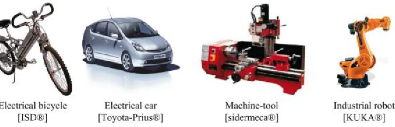
Today, t he P MSMs pl ay a n i mportant r ole i n the v ariable speed ap plications. T hese applications have the output capacity ranging from a few hundred 𝑊 (brushless DC micro-motor de veloped i n M EMS t echnology [MKP09]) t o m ore t han 1𝐺𝑊 (AC s ynchronous generator [Ber02]). F or s mall pow er machines, t heir r otor us ually consists of several permanent m agnets. T hese p ermanent m agnet sy nchronous m otors are also ca lled a s "brushless motor" because the rotor flux is still created by the magnets, they do not have the brushes collector.
Besides, se veral h igh performance ap plications su ch as r obotics an d aer ospace actuators in w hich th ere is a re quirement f or high to rque p er in ertia ra tio a re a lso th e typical applications of PMSM. In the next part, examples in different power ranges using PMSM will be presented.
1.2.1 Small power applications of PMSM
In t he r ange of s mall pow er ( according t o t he standard N F C 51 -200, the pow er i s under 600W), the brushless motors are mostly used in continuous current mode and called BLDC motors.
In order to control the system with the BLDC motors, an electrical sensor, which are connected to t he m otor, a llows the de tection of t he r otor pos ition a nd e nsures t he
a) surface mounted permanent magnet synchronous machine (SPMSM)
b) interior permanent magnet synchronous machine (IPMSM)
continuous switching of the current. The advantage of such a system is no additional speed control is required.
These t ypes of motor a re us ually us ed i n t he s ystems w hich a re r equired t o c ontrol exactly the position (hard disk drives, DVD rewrite …). They are also used in the systems that need t o operate a t a f ixed s peed p recisely su ch as t he m echanical t imer i n t he household devices. Other applications which use the small brushless motors are the fans of the micro-computers or the medical instruments such as the drills. All of these examples are illustrated in Figure 1.3.
1.2.2 Medium power applications of PMSM
In this section, the studied systems are required in the range of power from 500W to 100kW a nd us ing or l ikely t o us e t he P MSM. T hese m achines a re mostly pol y-phase (usually three-phase) and always associated with a voltage inverter controllable in current in order to ensure the autopilot.
One of the first applications in this power range is supported by t he motorization of various electric v ehicles. I n d eed, cu rrent t rends l ead to t he d evelopment o f el ectric accumulators (batteries Lithium/ion …) and the development of electric motors in order to replace t he internal combustion engines whose performance i s very l ow while t he fossil fuel b ecomes ex hausted. Mo reover, b rushless m otors a lso p ossess interesting characteristics w hich ar e su itable for e mbedded sy stems. S everal el ectrical o r h ybrid vehicles such as T oyota-Prius or the Citroen-C0 were equipped with PMSM. In the same tendency, the studies on t wo-wheeled vehicles are also carried out (scooter, electric bikes …).
Some machine tools and industrial robots also use the brushless motors because they provide goo d pe rformance ( good low-speed t orque, s trong overload c apacity, r eliability, speed …) and require little maintenance.
All the examples described above are illustrated in Figure 1.4
Thanks to many advantages, the PMSM can also be used in various driving mechanism for the specialty systems where the weight and volume play an important role. Therefore, if there are already the applications using the PMSM for some systems in cars (ventilations, air conditioning …), it is also possible to increase their penetration into other areas such as aerospace where the problem "more electric aircraft" is increasingly mentioned.
1.2.3 High power applications of PMSM
Despite the high cost of the magnets, PMSMs are increasingly used or considered for higher pow er a pplications i n w hich t here a re strictly r equirements a bout t he di mension space such as the electric traction drives or marine propulsion systems.
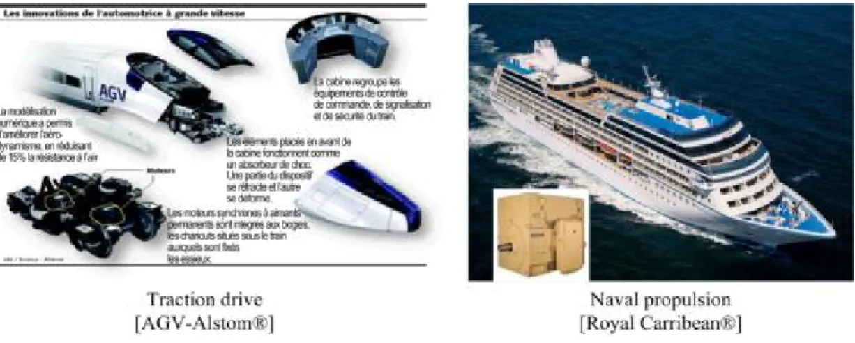
The A GV ( high sp eed electric r ailcar), a p roduct o f A lstom co mpany, al so u ses t he PMSM f or the t raction dr ive a nd e lectrodynamics br aking s ystems of t he t rain. T he successor o f T GV t rain r econciles al so the articulated structure (like T GV) w ith a distributed drive s ystem t hroughout t he train. T his di stribution br ings t o a reduction in consumption of 15% and a division the train into small parts as well as small power units. The p ower/weight ra tio o f th e tra in i s 22k W/tone a nd c ruising s peed of t he t rain i s 360km/h ( against 320k m/h for t he T GV). T he us ed e ngines ha ve a no minal pow er of 720kW and the power/weight ratio of 1kW/kg (against the maximum value 0.7kW/kg for asynchronous motor) [AGV07].
Similarly, the PMSM can be used for naval propulsion. In this context, the motors used must be compact, lightweight, reliable and resistant to the marine environment (vibrations, humidity, s alinity, te mperature … ). In s ome s pecial c ases a s m ilitary applications, th ey also are required as discrete as possible. Although PMSM that can generate the high power are quite expensive to manufacture, they still appeared on some submarines and military
ships as well as on some cruise ships such as the "Legend of the Seas" (as shown in Figure 1.5).
This section has proposed an overview of the different systems that promote the use of PMSM. T hese sy stems m ostly u se sev eral s ervo-electric m achines an d each o ne i s connected to its own electrical converter. These developed systems are of the type multi-machine. I t is i nteresting t o se e w hether i t w ould b e p ossible to o ptimize t he si ze an d weight of such these systems.
1.3
Multi-machine system in aeronautic field
1.3.1 The idea of sharing structures
Within the framework of the More Electric Aircraft (MEA), there is a trend of using the m ore an d m ore el ectric m achines [ROAR07][AF09], whether f or t he f light control actuators (see section 1.3.2), or for other mechanical parts such as the landing gear, brakes, fuel pumps, defrosting systems, air conditioning systems, startup of motors, door locks … In order to operate such these systems, each engine needs a p ower electronic device which consists of a heavy and bul ky cooling component. This element will i ncrease t he weight a nd s ize of t he w hole system s ignificantly. Moreover, for t he a eronautic applications, which require the high fail-safety, it is necessary to have strictly constraint redundant systems. These systems are essentially to ensure the continuous operation of the whole system even when any problem happens. However, they also make the system much heavier and larger.
On t he ot her ha nd, dur ing e ach s pecific pe riod of t he flight, t here a re j ust a c ertain number of drive systems which require the power electronic devices and are used while
many ot hers are i n i nactive mode. For example, t he door opening systems are j ust used only when the aircraft is at the stop. The landing gear, wing flap or thrust reverser systems also are only used for a f ew minutes during the whole flight. It is interesting to consider whether possible to use sharing structures to operate individual systems according to the availability of sequencing while respecting the continuous condition of system.
The next part of this section will focus on the flight control system and the actuators which require multiple PMSMs operating with the same function at the same time.
1.3.2 Flight control systems
1.3.2.1 Introduction
As represented i n Figure 1.6 , t he P MSM c an be us ed f or m any s ystems on t he airplane. The flight control systems are shown in the Figure 1.7, consists of two actuation parts [Nfo06][Del08]:
+ The primary part is the critical part of each flight which controls the evolution of the aircraft along three axes: roll (by the ailerons on trailing edges of wings), pitch (by the elevators on trailing edge of tail plane), yaw (by the rudder). + The s econdary pa rt c ontrols t he a erodynamic c onfiguration of t he a ircraft
during landing and takeoff processes (lift system, spoilers …). There are three main parts in the secondary actuation system: the flaps and the slats which are used for take off, landing and increasing lift at low speed, the airbrakes which increase the dr ag. T hese c omponents a re no t a ctually required f or f light but they cannot be omitted.
Figure 1.8 shows an example of secondary flight control of an airbus A300. The two lift devices (slats and flaps) allow their wings to maintain the lift at low speed.
Many studies in science and technology have been developed in order to upgrade the flight control system for the last many years [MGSL09]. At the beginning, flight control systems entirely use mechanical actuators: the pilot controls directly the rudder by taking the effect on the joystick. And then, with the support of the hydro-mechanical technology, the hydraulic actuators allow to operate heavier loads, however, the flight control issue is still always mechanical.
In the 1950s, military aircrafts began to be equipped by electric flight control systems. This technology, which is also called as "fly by wire", allowed reducing the weight of the system as well as i mproving t he r esponse t ime o f t he electro-hydraulic s ervo-system [Sch08].
Figure 1.6 The possibility of using PMSM in aeronautics [All95]
Figure 1.8: Wing of an airbus A300
In 1972, the Concorde is the first commercial aircraft using such flight control system (digital control system). In 1984, the Airbus A320 becomes the first commercial aircraft in which all the electric command signals are processed and generated by a digital computer [BT93].
In the last decade, a l ot of research has allowed Electro-Hydrostatic Actuator (EHA) technology to be mastered. One result of this on a new aircraft such as the Airbus A380 is the replacement of the hydraulic circuits by E HA networks. Although there is increasing interest in the use of electric drives to substitute hydraulics and electro-hydraulic system in aircraft, these devices are used just as a back-up for other hydraulic system.
Current a irplanes u sually u se the p resent h ydraulic o r electro-hydraulic a ctuators (EHA) in a centralized system. In the process of building the more electric aircraft, they will b e s ubstituted b y Electromechanical A ctuators (E MAs) in d e-centralized sy stems
(while respecting the c onditions of s afety).This t rend is today of major i mportance f or aeronautic o f industry. T his i mprovement w ill br ing the a dvantages of e liminating completely the hydraulic power, decreasing the production and maintenance cost as well as the weight of the system. An example of such EMA device is presented in Figure 1.9.
1.3.2.2 Electromechanical actuators (EMAs)
EMA drives for flight controls are based on direct drive architecture [LD12] built up by an el ectric motor co nnected d irectly t o t he r oller-screw t hat m oves a n act uator ( Figure 1.10). The complete control block diagram for an EMA drive includes the position, speed torque and flux c ontrols. B esides i t a lso i ncludes t he s upervisory a nd c ommunication system.
The more the EMA are used, the electric machines are also becoming more and more important in the general electric aircraft. As mentioned before, thanks to many advantages compared with other types of electric machines such as the high efficiency throughout the full s peed r ange, hi gh power ratio, an d ease o f r efrigeration, t he P MSM i s i ncreasingly being us ed f or a ctuator dr ives. I ndeed, t he f laps or t he slats of bot h w ings must be replaced simultaneously, which means that several PMSMs have to perform the same task at the s ame t ime. T herefore, th e multi-synchronous m achines s ystems ne ed t o be considered.
1.3.2.3 Shared structures
The objective of the study developed in this chapter is to look for a suitable structure of multi-synchronous machines m ono-inverter s ystem. T his s tructure must meet th e requirements of aeronautic applications about weight and volume especially in the case of imposing two or three redundant electronic systems with PMSM. The developed system is composed o f sev eral identical P MSMs w hich m ove d ifferent l oads a t t he sam e speed. There are two ways to approach to this problem.
+ The f irst w ay is ju st u sing o nly o ne in verter to o perate s everal P MSMs in parallel. According to this method, the weight of system will be decreased. + The second way is reusing a cl assical structure in which an individual inverter
can operate just one machine or two machines in parallel.
In t he ne xt pa rt of t his chapter, t he s ynthesis of e xisting s olutions w hich ha ve be en applied for multi-asynchronous machines system is presented. Then a short comparison is carried out in order to find the most suitable structure which can be applied to the multi-synchronous machines system, especially in aeronautics applications.
1.4
Typical structures of multi-machine system
1.4.1 Classical structure
In th e c lassical s tructure o f m ulti-machine system, eac h p hase o f a m achine i s connected and controlled by its own inverter's leg. For n three-phase machines, so there are m = 3n inverter's legs. The structure MS(3n, n) is described in the Figure 1.11.
In this case, as well as the cases which are mentioned afterwards, all the inverter's legs are connected to a DC bus that provides the voltage 𝑉𝐷𝐶.
In the vector representation of the complex voltage, 𝑂 is the middle point of the DC bus, (𝐴𝑙, 𝐵𝑙and 𝐶𝑙) represent the phases of the machine 𝑖 and 𝑁𝑙 is the neutral point. In
general, t he vo ltage re sulting f rom th e c ontrol o f th e machines is th ree-phased a nd balanced. T his relation i s t rue f or al l m achines an d i s r epresented by t he f ollowing equation:
𝑉𝐴𝑖𝑁𝑖+ 𝑉𝐵𝑖𝑁𝑖+ 𝑉𝐶𝑖𝑁𝑖= 0 (1.1)
Besides, in the case of the structure MS(3𝑛, 𝑛), with a classical pulse width modulation technique (PWM), the average value of the switching voltage 𝑉𝑁𝑖𝑂 can be zero. Therefore,
the r elations in (1.1) are f ormed a nd t here i s no ne ed of m odule of a daptation w hich is shown in Figure 1.1.
The diagram of voltage vectors applied to each different machine is shown in Figure 1.12. Neutral point of each machine and the the mid-point of DC bus are in common.
𝑉𝐴𝑖𝑁𝑖= 𝑉𝐴𝑖𝑂
𝑉𝐵𝑖𝑁𝑖= 𝑉𝐵𝑖𝑂
𝑉𝐶𝑖𝑁𝑖 = 𝑉𝐶𝑖𝑂
(1.2)
In t his c onfiguration, t here is no m utual c ontrol be tween di fferent i nverter. All machines operate independently from each others. The synchronism of the system can be obtained easily. However, using one inverter for each machine as well as one drive system needs an individual controller; such system can be expensive and bulky. These problems can be considered as the most negative point of this structure.
Figure 1.12: Diagram of voltage vectors under structure MS(3n,n)
Shared structures with 𝑁 < 3𝑛 then have been developed and studied; especially for induction machines. However, according to some specific conditions, it is also possible to apply these structures to the case of synchronous machines.
1.4.2 Presentation of the shared structures
In shared structures, several machines can have some common phases. These phases can be connected to the same legs of an inverter or a common point (the neutral point of a DC b us). T his i s b ecause o f t he f act t hat o ne inverter leg can g enerate an alternative voltage from the DC voltage, so a multi-phase (𝑥 legs) inverter can fed 𝑦 machines. These structures are marked as MS(x, y) [Bou95].
However, a multi-machine system may include several multi-phase inverters which are independent f rom e ach ot her. T herefore, a sy stem MS (m, n) will ha ve ny multi-phase inverters an d can b e ex pressed as MS�xny, n�. T he nu mber of t he m achines 𝑛 must be multiple of 𝑦. Some different sharing structures will be presented in the following parts of this section.
1.4.2.1 Sharing common legs structure: n machines with 2n legs
As shown in Figure 1.13, a system which is constructed under this structure consists of a f our-leg i nverter f eeding t wo machines. T he t wo pha ses 𝐵 and 𝐶 of two machines are connected t o the s ame l eg o f t he i nverter. T he r est p hase of each machine i s co nnected individually to its own leg. This structure is denoted as MS�4n2 , n�.
According t o t his c onfiguration, t wo machines w ill r un at e qual s peeds i n a bsolute value. It means that two motors can rotate in the same direction or in opposite directions. It is initially applied for mobile robot applications with the asynchronous machines [Sia92]. Under this configuration, the following relation is always obtained: 𝑉𝑂𝐵1 = 𝑉𝑂𝐵2 = 𝑉𝑂𝐵
and 𝑉𝑂𝐶1 = 𝑉𝑂𝐶2 = 𝑉𝑂𝐶
Figure 1.14 shows t he voltage ve ctors of t hree pha ses of two m achines unde r t wo cases: rotating in the same direction and rotating in the opposite direction.
+ 𝑉𝐴2𝑁2 = 𝑉𝐴1𝑁1 ⇒ Ω1 = Ω2 (Figure 1.14(a))
+ 𝑉𝐴2𝑁1 = −2𝑉𝐴1𝑁1 ⇒ Ω1 = −Ω2 (Figure 1.14(b))
The tri -phase vol tage obt ained w ill be r egulated t o f ollow a reference v alue b y a controller. T he c ontrol s ignal i s t hen s ent t o t he i nverter. I t s hould be not ed t hat, t he voltage applied to the inverter need to refer to the point 𝑂.
Figure 1.13: The structure using a common leg MS �4𝑛2 , 𝑛�
(a) Case 1: 𝐴2 = 𝐴1 (b) Case 2: 𝐴2 ≠ 𝐴1
In or der to ge t t he w ell adapted voltage t o apply to e ach l eg of t he i nverter, t he potential be tween t he ne utral poi nt of i nverter 𝑂 and t he ne utral poi nt of e ach machine 𝑁1and 𝑁2 need to be considered: �𝑉𝑁1𝑂�𝑟𝑒𝑟and �𝑉𝑁2𝑂�𝑟𝑒𝑟.
Therefore, the reference voltage must be calculated according to the equation in (1.3) This structure can be used to operate multiple machines which are required to rotate at the same speed ether in the same direction or in opposite.
The most advantage of this structure is that only a four-leg inverter is used in order to run two three-phase machines (compared with six legs in the case of classical structure). However, w ith t his s tructure, a n a daptation m odule ne eds to be us ed t o m odulate t he midpoint 𝑂 of a c ontinuous D C bus . T hanks t o t his, t he two vol tages �𝑉𝑁1𝑂�𝑟𝑒𝑟 and
�𝑉𝑁2𝑂�𝑟𝑒𝑟 can be regulated properly. Besides, it should be paid attention that each shared
leg of the inverter in this case has to withstand the higher current compared with the case of non-shared leg. It is reasonable because there are two currents who will pass through such these legs.
�𝑉𝐴1𝑂�𝑟𝑒𝑟= �𝑉𝐴1𝑁1�𝑟𝑒𝑔+ �𝑉𝑁1𝑂�𝑟𝑒𝑟
(𝑉𝐵𝑂)𝑟𝑒𝑟= �𝑉𝐵𝑁1�𝑟𝑒𝑔+ �𝑉𝑁1𝑂�𝑟𝑒𝑟
(𝑉𝐶𝑂)𝑟𝑒𝑟= �𝑉𝐶𝑁1�𝑟𝑒𝑔+ �𝑉𝑁1𝑂�𝑟𝑒𝑟
�𝑉𝐴2𝑂�𝑟𝑒𝑟= �𝑉𝐴2𝑁2�𝑟𝑒𝑔+ �𝑉𝑁2𝑂�𝑟𝑒𝑟
(1.3)
Based on the same principle (share the legs of the inverter), another structure expressed as MS (2n + 1, n) is a lso de veloped [DJVL09]. A (2n + 1) leg in verter w ill be u sed to operate 𝑛 machines. This means that there is just one leg is shared by only one phase of all machines. T his s tructure c an be us ed i n r olling-up applications i n paper i ndustry [JVD+08].
1.4.2.2 Sharing the midpoint structure: n machines and 2n legs
According to t his s tructure, t wo phases o f ea ch m achine w ill b e co nnected t o two separated legs of an inverter and the third phase of both machines is shared and connected to the neutral point O of the continuous DC bus which feed the inverter. This configuration is called MS(2n, n) and shown in Figure 1.15.
Using this structure, the two motors can run at different speed. Figure 1.16 represents the di agram of t hree-phase v oltage v ectors o f t wo motors. E ach m otor c an o perate independently [Bou95][FOM07].
Because the third phase of each machine is fixed to the neutral point 𝑂, for any motor, the re lation 𝑉𝑂𝐴𝑖 = 0 is a lways tru e. A t th e e quilibrium o f a ll m achines, the re lation
𝑉𝑂𝑁𝑖 = −𝑉𝐴𝑖𝑁𝑖 is also assured.
As in the case of using the common legs of the inverter, the reference voltage applied to the inverter's legs will differ from the voltage calculated by t he regulator. For the 𝑖𝑙ℎ
machine, the reference voltage will be obtained from the relation in (1.4).
�𝑉𝐵𝑖𝑂�𝑟𝑒𝑟 = �𝑉𝐵𝑖𝑁𝑖�𝑟𝑒𝑔+ �𝑉𝑁𝑖𝑂�𝑟𝑒𝑟
�𝑉𝐶𝑖𝑂�𝑟𝑒𝑟 = �𝑉𝐶𝑖𝑁𝑖�𝑟𝑒𝑔+ �𝑉𝑁𝑖𝑂�𝑟𝑒𝑟
with �𝑉𝑁𝑖𝑂�𝑟𝑒𝑟 = −�𝑉𝐴𝑖𝑁𝑖�𝑟𝑒𝑔
(1.4)
One of t he a dvantages of t his s tructure i s t hat the motors can ope rate i ndependently with each others, while the number of power electronic components can be reduced.
Figure 1.15: The structure sharing the midpoint MS(2𝑛, 𝑛)
However, t o im plement th is s tructure in a pplications, t he n eutral point o f t he continuous DC bus must be accessible in order to regulate the reference voltage. It is not easy to solve this problem, especially in aeronautics systems.
1.4.2.3 Mixed structure: 3n
2 legs for n machines
In accordance with its name, the mixed structure, which is represented in Figure 1.17, is a combination of two structures which are mentioned above. According to this structure, a three-leg inverter is used to operate two motors. One phase of both motors will be shared and c onnected t o a c ommon l eg o f i nverter ( Figure 1.17, t wo p hases 𝐶1 and 𝐶2) w hile
another phase of both motors (𝐴1and 𝐴2) is linked to the neutral point O. The third phase
is connected to its own legs of the inverter. This structure is named as MS�3𝑛2 , 𝑛�.
As shown in Figure 1.17, the phase A of two machines is connected to the midpoint O ⇒ 𝑉𝑂𝐴1 = 𝑉𝑂𝐴2 = 0 and the phase C of two machines is linked to the same leg ⇒ 𝑉𝑂𝐶1 =
𝑉𝑂𝐶2 = 𝑉𝑂𝐶.
The diagram of voltage vectors of two machines under the mixed structure is shown in the Figure 1.18.
Moreover, like in the structure with common leg, two possibilities can happen: + if 𝑉𝐵2𝑁2 = 𝑉𝐵1𝑁1 ⇒ Ω1 = Ω2 (Figure 1.18(a))
+ if 𝑉𝐵2𝑁2 = −2𝑉𝐵1𝑁1 ⇒ Ω1 = −Ω2 (Figure 1.18(b))
+ Therefore, the reference voltages applied to the inverter will be calculated by the equation (1.5):
�𝑉𝐵1𝑂�𝑟𝑒𝑟 = �𝑉𝐵1𝑁1�𝑟𝑒𝑔+ �𝑉𝑁1𝑂�𝑟𝑒𝑟 �𝑉𝐵2𝑂�𝑟𝑒𝑟 = �𝑉𝐵2𝑁2�𝑟𝑒𝑔+ �𝑉𝑁2𝑂�𝑟𝑒𝑟 (𝑉𝐶𝑂)𝑟𝑒𝑟 = �𝑉𝐶𝑁1�𝑟𝑒𝑔+ �𝑉𝑁1𝑂�𝑟𝑒𝑟 with �𝑉𝑁1𝑂�𝑟𝑒𝑟 = −�𝑉𝐴1𝑁1�𝑟𝑒𝑔 �𝑉𝑁2𝑂�𝑟𝑒𝑟 = −�𝑉𝐴1𝑁1�𝑟𝑒𝑔if 𝐵2= 𝐵1 �𝑉𝑁1𝑂�𝑟𝑒𝑟 = −�𝑉𝐶1𝑁1�𝑟𝑒𝑔if 𝐵2≠ 𝐵1 (1.5)
This s tructure, l ike t he s tructure s haring t he midpoint, h as t he s ame di sadvantage because of having to access to the neutral point of the DC bus to adjust the potential. In spite of decreasing the number of inverter's legs, this structure just is used in some specific applications.
1.4.2.4 Parallel structure: 3 legs for n machines
This s tructure be longs to t he t ype M S(3, 𝑛), a t hree-leg i nverter w ill o perate n machines s imultaneously. S ome s tudies c an b e found i n t he l iterature [KFM00] [PE02]. According to these studies, the case of two machines in parallel is focused. As s hown i n Figure 1.19, each l eg of t he i nverter is sh ared b y al l t he m achines. T herefore, t he dimension of the power electronic components of the inverter must be in accordance to the number of m achines i n p arallel. B esides, these m achines m ust b e as similar as p ossible about electrical parameters.
According to this structure, all the machines will receive exactly same voltages in both frequency and amplitude. These machines will be set up at the same initialization; the same
(a) Case 1: 𝐵2 = 𝐵1 (b) Case 2: 𝐵2 ≠ 𝐵1
stator f lux i s cr eated i n each m achine. T he a ngular sp eeds o f t he m achine t hus ar e identical: Ω𝑙 = Ω𝑗∀(𝑖, 𝑗) ∈ [1, ⋯ , 𝑛]2.
Contrary to those previous structures, it is impossible to control all the phase voltages of t hese machines. S uitable m ethods ne ed t o be c onsidered a nd de veloped i n or der t o guarantee the stability of such these systems.
1.4.2.5 Some other structures
Some other structures, which are more complex such as MS�6n6 , n� or MS�6n4 , n�, have also been studied [Bou95]. These structures which are based on the same principle of using common l egs or m ixed s tructure w ere us ed i n many a pplications h aving more t han t wo machines.
Another principle has been also developed in the field of multi-machine system which is us ing i nverters or m achines w ith s pecial topology [SH07]. However, s uch t hese particular systems are not easily adaptable in replacing the redundancy systems.
1.4.2.6 Comparison of these different structures
In previous parts, many different structures developed for multi-machine systems have been presented. To see which structure is more suitable according to the requirements of aeronautic applications in section 1.3.2.3, a comparison of those structures is provided in Table 1.1.
In this table, besides the advantages and disadvantages of these developed structures, several other criteria also are considered and pointed out.
+ The first criterion is the number of the inverter's legs per machine. Normally, a three-phase A C machine w ill b e c ontrolled i ndependently by a three-leg inverter. T he s tructures us ing c ommon l egs will de crease t he num ber of inverter's legs. This means that the number of power electronic components is also r educed. H owever, us ing c ommon l egs w ill l ead t o t he pr oblem that t he current passing through these legs will be higher. Therefore, there are different electronic devices inside one inverter.
+ The second criterion is the ratio between the maximum voltage that a machine can receive (𝑉𝑁𝑙)𝑙𝑙𝑥 and the maximum voltage which can be generated from
the inverter (𝑉𝑂𝑙)𝑙𝑙𝑥. Denote this ratio as 𝜂𝑉 =(𝑉(𝑉𝑁𝑖)𝑙𝑙𝑥
𝑂𝑖)𝑙𝑙𝑥. For the classical and
parallel structure, this ratio is 𝜂𝑉 = 1 while with other structures this ratio is
always sm aller t han (𝜂𝑉 < 1). T herefore, f or t he s tructures w hich make t he
ratio 𝜂𝑉 < 1. , the value of the DC bus 𝑉𝐷𝐶 needs to be regulated.
+ For the structures that can be used for only one machine, it is possible to obtain independent c ontrol be tween di fferent m achines e asily. H owever, f or s haring structures, it is n ecessary to lo ok for s uitable c ontrol structures as well a s control algorithms to ensure the stable operation of each machine.
The parallel structure presents the best advantage of using as less as possible number of inverter's legs. Moreover, it is not necessary to modulate the voltage of the DC bus (𝑉𝐷𝐶)
in order to obtain the same machine voltage when compared with the case of conventional structure. It is not too difficult to apply this structure in real applications. The drawback of this structure comes from sharing all inverter's legs. Because being connected to the same legs, all phases of all the machines will not be controlled independently. In fact, when 𝑛 machines are put into parallel, the current passing through each leg will be 𝑛 times higher than that of the classical structure. The problem will come from the design of the electronic devices. However, using these oversized components in the redundancy systems, which are inactive most of time, is is still an acceptable solution.
Therefore, parallel structure is selected as the most feasible solution for the aeronautic application based in the secondary flight control system. In the case of detecting a failure in an inverter of a machine, it w ill be possible to switch to this structure to guarantee the continuity of the whole system.
1.5
Conclusions
The rapid development of semi-conductor and material technology has allowed the use of increasingly the PMSM in industry, replacing the current electric machine types. Along with this, it is the development of embedded systems with the strictly requirements about the performance, quality, weight, size … This is the case in aeronautics field where the concept of “More Electric Aircraft” now becomes a reality.
When these machines are associated to carry out cooperative functions (for example, in flight surfaces), it is a time that a sharing structure needs to be considered and developed. This c oncept ha s a lready be en a pplied f or the a pplications w ith induction m otors. However, for PMSM, there is still limit. A structure including two or more synchronous machines is really interesting.
In this first chapter, several structures of multi-machine systems has been presented and compared. According to the comparison given and analyzed, parallel structure seems to be the m ost s uitable f or the a eronautic applications. It us es t he least number of pow er electronic d evices, do es not r equire a ccessing t o t he D C vol tage bu s and s o i t is qui te simple to implement. However, according to this structure, because all machines obtain the same vol tage f rom o nly one i nverter, it is difficult t o satisfy i ndependently the requirements of all machines, especially in the case of different loads.
In the next chapter, a two-parallel PMSM system will be described. The solutions used to control this system will be introduced and analyzed.
Structure’s name MS(m,n) Number of legs per machine (𝑉𝑁𝑘)max (𝑉𝑂𝑘)max Relation
Speed Volume Notes
Advantages Disadvantages
Classical MS(3𝑛, 𝑛) 3 1 independent large Independent machines Non-sharing
Common legs MS�4𝑛2, 𝑛� 2 2 3 Ω1= Ω2 or Ω1= −Ω2
average implement Easy to Over current in common
legs
Midpoint MS(2𝑛, 𝑛) 2 √31 independent average Can apply for 1
machine
Access to neutral point
Mixed MS�3𝑛2, 𝑛� 1.5 √31 Ωor Ω1= Ω1=2
−Ω2
small the previous Inherit from the previous Inherit from
Parallel MS(3, 𝑛) 3
𝑛 1 Ω1= Ω2 small
Easy to
implement Over current in all legs
Chapter 2
Mono-Inverter Dual-Parallel PMSM drive
system
Table of Content
9T
2.19T 9TIntroduction9T ... 28 9T
2.29T 9TGeneralities about PMSM drive system9T ... 29 9T 2.2.19T 9TPrinciple of operation of PMSM9T ... 30 9T 2.2.29T 9TModeling of PMSMs9T ... 31 9T 2.2.2.19T 9TElectromechanical description9T ... 31 9T
2.2.2.29T 9TContinuous model of PMSM in d-q reference frame9T ... 34 9T
2.2.39T 9TStability analysis of PMSM9T ... 36 9T
2.2.49T 9TA three-phase two-level voltage inverter9T ... 39 9T
2.39T 9TControl strategies for PMSM drive9T ... 39 9T
2.3.19T 9TField oriented control9T ... 40 9T
2.3.29T 9TDirect Torque Control (DTC)9T ... 41 9T
2.3.39T 9TDirect Predictive Torque Control (DPTC)9T ... 44 9T
2.49T 9TControl structure for Mono-inverter Dual-parallel PMSM system9T ... 46 9T
2.4.19T 9TMaster-slave structure9T ... 46 9T
2.4.1.19T 9TGeneral description9T ... 46 9T
2.4.1.29T 9TConsequence due to a load variation9T ... 47 9T
2.4.1.39T 9TThe choice of master machine9T ... 48 9T
2.4.1.49T 9TConclusions9T ... 52 9T
2.4.29T 9TDirect torque control (DTC) for mono-inverter dual-parallel PMSM9T ... 52 9T
2.4.2.19T 9TGeneral description9T ... 53 9T
2.4.2.29T 9TOptimal switching table for two machines9T ... 55 9T
2.4.2.39T 9TSimulation tests9T ... 61 9T
2.1
Introduction
As mentioned i n pr evious c hapter, multi-machine sy stems b ecome more an d more popular in variable s peed a pplications. T he pr oblem of u sing m any pow er e lectronic devices w hich i ncreases t he w eight an d si ze o f t hese systems is s olved by the i dea of sharing structures.
In a ddition, t he de velopment of t he s ystem w ith m ultiple machines a lso l eads t o a higher at tention i n sel ecting su itable el ectrical machines. I n t his f ield, t he P MSMs gradually become dominant compared with others such as DC machines, IMs...
In the special field of aeronautic applications where the efficiency as well as the weight and size are the most important things, the parallel structures along with PMSMs seem to be the best choice.
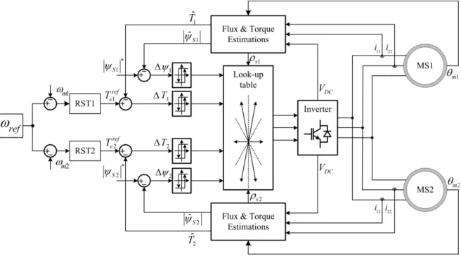
Combining parallel structures with PMSM leads to the idea of multiple PMSMs drive system. Until now, few studies have been developed in order to control this kind of drive systems. T hese s tudies focus on a drive system i ncluding t wo P MSMs c onnected t o a three-phase i nverter [CSSS02][BPDMF08][PIS10]. S uch t hese sy stems ar e al so cal led mono-inverter dual-parallel PMSM (Figure 2.1).
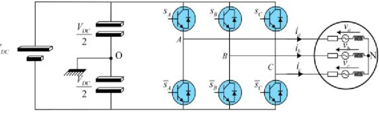
According to Figure 2.1, a drive system including two PMSMs connected in parallel and supplied by a three-phase two-level inverter is presented. In this kind of drive system,
two machines are identical. It means that all parameters of both machines are the same. Besides, both machines will receive the same voltage (magnitude and frequency):
�|𝑉𝑠1| = |𝑉𝑠2| = |𝑉𝑠|
𝜔𝑒1 = 𝜔𝑒2 = 𝜔𝑠 (2.1)
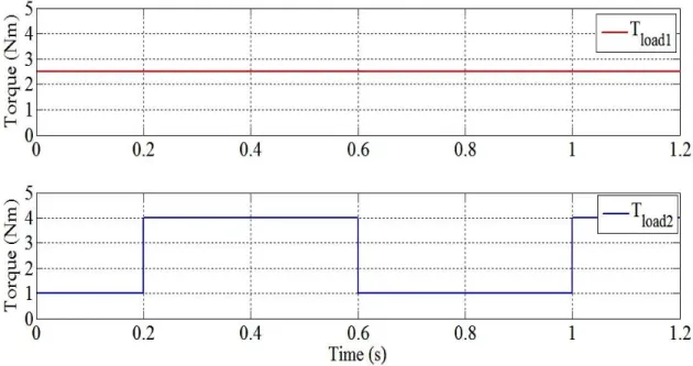
For this system, the aim is to keep the mechanical speeds of two machines equal and follow the speed reference under different load conditions:
𝜔𝑙1 = 𝜔𝑙2= 𝜔𝑟𝑒𝑟
𝑠. 𝑡 𝑇𝑙𝑙𝑙𝑠1 ≠ 𝑇𝑙𝑙𝑙𝑠2
(2.2)
In t his ch apter, a g eneral d escription ab out a P MSM d rive sy stem w ill b e p resented first. In th is p art, th e p rinciple of o peration a nd s tability analysis o f a P MSM a re considered. In order to operate this drive system, some typical methods will be presented in the next part. Finally, two control strategies for mono-inverter dual-parallel PMSM drive will be described.
2.2
Generalities about PMSM drive system
PMSM n ormally i s n ot a s elf-started m otor t ype. T herefore, i n variable sp eed applications, a P MSM is u sually s upplied b y the v ariable f requency sources su ch as voltage s ource i nverter (VSI), c urrent s ource inverter ( CSI)… G eneral structure of s uch drive system is presented in Figure 2.2.
In t his f igure, a P MSM i s su pplied b y a t hree-phase t wo-level vol tage i nverter. A controller will be used to generate the control signals of the inverter in order to control the PMSM.
2.2.1 Principle of operation of PMSM
In t he c ase of a PMSM, t he r otor a cts a s a n i nductor, c ontaining 𝑛𝑝 pairs of pol es
(North a nd South) pe rmanent magnets. M eanwhile, t he s tator of a t hree-phase P MSM normally has a sine distributed three-phase winding. When these windings are excited with a three-phase balanced supply, a rotating magnetic field is developed. It is assumed that this field is sinusoidally distributed in the air gap. The mutual impact between the stator and rotor magnetic fields will produce forces to the rotor and will make the rotor rotate. At steady state, PMSM is a constant speed motor. This speed is calculated by equation (2.3):
𝜔𝑙 = 60𝑛𝑓𝑠
𝑝 (2.3)
where 𝜔𝑙 is the mechanical speed of the rotor (𝑟𝑝𝑁);
𝑓𝑠 is the electrical frequency of the voltage supply (𝐻𝑧);
𝑛𝑝 is the number of pole pairs;
Figure 2.3 is an example of a three-phase motor with 𝑛𝑝 pole pairs (𝑛𝑝 = 2). It consists
of 3𝑛𝑝 pairs of windings which are spaced 2𝜋/�3 × 2𝑛𝑝�(𝑟𝑟𝑟).
In o rder to g et th e b est c ontrol p erformance o f a d rive system w ith P MSMs, t he characteristic eq uations w hich d escribe the e lectrical an d mechanical r elations o f t he machine w ill be s tudied. T he modeling a nd s tability a nalysis ha ve b een done i n t he following parts.
2.2.2 Modeling of PMSMs
In a r otating electrical machine, there is always a rotating component and a st ationary one. Because of this rotation, the self and mutual inductances, which are responsible for various voltages, become time varying. These time varying inductances sometimes cause difficulties for the analysis. Besides, rotor flux in a PMSM is constant and provided by the permanent m agnets. T hank t o t his, r otor f lux i s a lways pol arized an d has a cl early an d consistently oriented shaft. If using a position sensor (such as resolver, encoder with zero pulse), t he position of t he r otor f lux c an be s pecified pr ecisely a nd f or t his r eason, t he problem of flux oriented always can be ensured.
Therefore, in this section, a model of a three-phase PMSM in d-q reference frame is derived in order to clarify the concept of the axis transformation (Park) and the relation between three-phase quantities and their equivalent two-phase quantities.
Throughout the derivation of the two-phase (d-q) mathematical model of PMSM, the following assumptions are pointed out [Kri01]
+ Stator windings produce sinusoidal EMF distribution. Space harmonics in the air-gap are neglected;
+ Air-gap r eluctance h as a co nstant co mponent as w ell as a si nusoidal v arying component;
+ Balanced three-phase sinusoidal supply voltage is considered;
+ Although magnetic saturation is considered, eddy current and hysteresis effect are neglected;
+ Presence of damper windings is not considered because PMSMs used today rarely have that kind of configuration.
As mentioned i n p revious c hapter, there a re t wo t ypes of PMSM de pending on the rotor s tructure. I n S PMSM, magnets a re m ounted on t he s urface of t he r otor. S ince t he permeability of magnets is close to unity and the saliency is really small, the inductances expressed i n t he d -q c oordinates a re a pproximately e qual. I n t his t hesis, j ust non -silent typed P MSMs a re c onsidered. T herefore, the f ollowing relation is always c onfirmed: 𝐿𝑠 = 𝐿𝑠 = 𝐿.
2.2.2.1 Electromechanical description
The space vector form of the stator voltage equation in the stationary reference is given in Equation (2.4):