HAL Id: hal-02266618
https://hal.archives-ouvertes.fr/hal-02266618
Submitted on 15 Aug 2019
HAL is a multi-disciplinary open access
archive for the deposit and dissemination of
sci-entific research documents, whether they are
pub-lished or not. The documents may come from
teaching and research institutions in France or
abroad, or from public or private research centers.
L’archive ouverte pluridisciplinaire HAL, est
destinée au dépôt et à la diffusion de documents
scientifiques de niveau recherche, publiés ou non,
émanant des établissements d’enseignement et de
recherche français ou étrangers, des laboratoires
publics ou privés.
SCHC-Based Solution for Roaming in LoRaWAN
Wael Ayoub, Mohamad Mroue, Abed Samhat, Fabienne Nouvel,
Jean-Christophe Prévotet
To cite this version:
Wael Ayoub, Mohamad Mroue, Abed Samhat, Fabienne Nouvel, Jean-Christophe Prévotet.
SCHC-Based Solution for Roaming in LoRaWAN. The 14-th International Conference on Broadband and
Wireless Computing, Communication and Applications (BWCCA-2019), Nov 2019, Anvers, Belgium.
�hal-02266618�
SCHC-Based Solution for Roaming in
LoRaWAN
Wael Ayoub1, Mohamad Mroue2, Abed Ellatif Samhat2, Fabienne Nouvel1,
and Jean-Christophe Pr´evotet1
1 Institut National des Sciences Appliqu´ees de Rennes — IETR-INSA, Rennes,
France.
2
Faculty of Engineering - CRSI, Lebanese University, Hadath Campus, Hadath, Lebanon
{mohamad.mroue,samhat}@ul.edu.lb
Abstract. To take advantage of IPv6 stack in IoT technologies, an ef-ficient header compression scheme is required. Since 2004, many IPv6 header compression schemes have been proposed and some of them have been standardized by the IETF. In [9], Static Context Header Compres-sion (SCHC) mechanism has been designed for Low Power Wide Area Networks (LPWAN). SCHC compression is based on a common static context stored in both the IoT device and the network side. This static context defines the compression and decompression rules of the headers. The SCHC framework is compatible with LoRaWAN v1.0 [2] but not with LoRaWAN v1.1 that supports roaming of devices during mobility between different LoRaWAN operators. During roaming, the header val-ues of the protocol stack change and are no longer static. In this paper, we propose a solution based on SCHC to support roaming of devices dur-ing mobility between different LoRaWAN operators. We define a server to manage the context between operators. In addition, the LoRaWAN frame route and the communication scheme are updated. A testbed has been setup to show the time differences between current LoRaWAN net-work and our proposal. The results shows that our proposal improves the communication process and decreases the time delay to handle the transmitted messages ”uplink” before the registration.
Keywords: IoT communication · LPWAN · LoRaWAN · IPv6 · Long-Range · Mobility · Roaming · SCHC.
1
INTRODUCTION
LoRaWAN is an open standard architecture developed by LoRa Alliance [2] to provide a medium access control mechanism and enable End-Devices (ED) to communicate with one or more gateways (GW). A GW is seamless to an ED, where an ED sends data when available without considering location change, movement, and speed of motion. In addition, any GW that receives the message will forward it to the NS. In the latest version of LoRaWANv1.1 [1], specifications
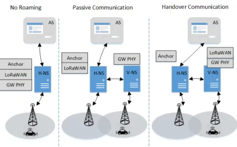
address the mobility of devices. They define the coverage of the home operator, as a home network server (H-NS), and the coverage of the foreign operator by a Visited Network Server (V-NS) as shown in Figure 1. LoRaWAN specifications define two roaming scenarios: the passive and the handover. We discriminate between these two roaming types based on the LoRaWAN communication stack. This stack consists of three layers: the anchor, the LoRaWAN and the Gateway controller. The anchor is responsible for the communication between the NS and the Application Server (AS). It also communicates with the Join Server (JS) to manage the state of the device and the registration parameters to associate the device with the NS. The second layer of this stack is the L2 controller, which is the LoRaWAN protocol. This layer specifies the functionality of the LoRaWAN link layer found in the specification, such as Adaptive Data Rate (ADR) management, device location, communication, etc. The third layer is the gateway controller. This layer defines the communication between the NS and the GWs that cover different areas. This layer is responsible for the functions of the PHY layer, such as the radio access network, the power transmission, etc. As can be seen in Figure 1, in case of no roaming, the device is associated with the H-NS which contains all three layers. After roaming, if the collaboration between the two network operators is passive, only layer three i.e. Gateway controller will be assigned to the V-NS. In this case, the V-NS will be considered as a GW to extend the H-NS coverage. In the handover collaboration, the second and third layers will be assigned to the V-NS. The device will be associated with the V-NS and a registration process is required to access the network to send/receive data. However, the anchor layer is maintained with the H-NS. Therefore, any packet received from the ED by the V-NS will be forwarded to the H-NS and then sent to the corresponding AS.
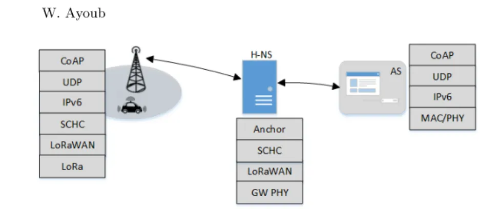
In addition to the three layers specified in LoRaWAN v1.1, the SCHC pro-tocol [9] is a propro-tocol for compressing/decompressing headers in the commu-nications stack. This mechanism is placed as a layer between the Anchor and LoRaWAN layers in case of no roaming. The SCHC standard is defined to in-stall this layer on the ED and the NS or on a separate server within the home network. Since the H-NS reserves the Anchor layer to communicate with the AS, the logic is to keep the SCHC layer with the anchor layer. Therefore, the communication procedure will be as shown in Figure 2. In both roaming cases, the SCHC layer and the anchor were reserved for H-NS. Then, the communica-tion procedure will be as follows. In passive communicacommunica-tion, the ED sends the uplink to the GW. Uplink is the message transmitted by ED towards AS. Then, the GW forwards the LoRaWAN frame to the V-NS. Because the device is not assigned to the V-NS, there is no network session key to decrypt the payload of the frame. Thus, the LoRaWAN frame is forwarded to the H-NS. In the H-NS, the frame is decrypted using the network session key and the frame payload is executed. This payload will be decompressed using the SCHC layer. Then, it will be forwarded using the anchor to the corresponding AS. In the AS, the received payload will be decrypted using the application session key and the data will be available to the user. In handover communication, the device is associated with
SCHC-Based Solution for Roaming in LoRaWAN 3
Fig. 1. Communication schemes support on LoRaWANv1.1
the V-NS, the received LoRaWAN frame is decrypted in the V-NS and the com-pressed payload is sent back to H-NS. Then, the payload is decomcom-pressed using the SCHC layer in the H-NS and the final payload is sent to the AS to decrypt the user data. In this case, it is not necessary to share the context of the device as it moves between different foreign network providers. But if we consider that the V-NS and the AS are in the same network topology, this form of implementation is not efficient in terms of bandwidth usage, routing, power consumption, and communication latency. During downlink i.e. transmitted message from AS to ED, latency is an important and considerable parameter, especially if the down-link is an acknowledgment (ACK). For example in LoRaWAN class A devices, two windows open after an uplink, with one second time for each. Therefore, within two seconds the device have to receive the ACK. Otherwise, the uplink is repeated. This consumes more energy, and causes collisions and interference with other devices as the number of devices in the area increases. Also, increasing listening time is not efficient in terms of energy consumption.
From our observation, there is still no work related to SCHC mobility or Lo-RaWAN roaming. Next, we illustrate the proposal of the communication mecha-nism in section 2. Then, this mechamecha-nism will be implemented and tested as shown in section 3. Finally, section 4 concludes and summarizes our contributions.
2
Roaming enhancement
In this section, we propose a mechanism that allows the use of the two layers: anchor and SCHC, by the V-NS in order to optimize the communication routing. For this purpose, an Administration Management Server (AMS) is added to the
Fig. 2. Protocol stack at each component
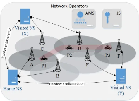
LoRaWAN network. In parallel to the Join Server (JS), the AMS is responsible for the devices belonging to the H-NS. The AMS will manage the registration and exchange the SCHC context, the geographic location of the devices and perform a pre-registration with the V-NS. It will include a routing table for each device that belongs to the network. It can also save the data message rate and manage the power of the device. AMS is responsible for the network topology formed by the GWs and network operators to which the device can access. In addition, when AMS detects the geographical location [7, 4] of the device, it verifies whether roaming is necessary or not. Then, AMS performs a preregistration process for a device and sends the new parameters through a downlink message ACK before the connection to the current GW is lost. This functionality can also be added to the H-NS, but it adds a load to the H-NS as the number of devices increases, and especially when it comes to SCHC. For this, it is preferable to add the AMS as an independent server in the LoRaWAN network that is formed by H-NS and its V-NS partners, as shown in figure 3.
In loRaWAN, geolocation management is quite easy. Each GW of LoRaWAN has a wide coverage. In addition, the GW is a physical repeater of the up-links/downlinks to the NS. An NS can cover a part of a city and more. There-fore, in LoRaWAN when it comes to geolocation, it is not necessary to wait for a point location for the car or wait exactly for GW coverage, since the device is associated with NS and not with GW. It is easy to deal with it as a car moving from a city covered by more than one GW that belongs to H-NS to another city covered by the GWs of V-NS(X). In this article, we deal with a wide geolocation specified by an operator’s coverage, while knowing the coverage of each GW will not make a difference Therefore, the management of the location of the devices is an important feature in the AMS. As shown in Figure 3, while the car moves from position one (P1) to position two (P2), the AMS detects the degradation in the RSS of the packets received by the GWs of the H-NS. The AMS knows the covered area of each NS. The movement of the automobile can be predicted from the road maps. Therefore, as in [7], AMS can expect from the geographical location of the car and the known NS coverage the next network operator the car will cross. Then AMS contacts this operator to inform it about the car. When
SCHC-Based Solution for Roaming in LoRaWAN 5
Fig. 3. Proposed LoRaWAN network
an uplink message is received from ED, the NS can accurately detect the closest GW to the car and can specify a more accurate location for the AMS.
During the movement of a car between GWs, AMS has to face two cases. First, if the operator coverage is H-NS or V-NS with passive roaming collab-oration, AMS does not step in the communication process. In this case AMS only used in the compressing/decompressing process of the SCHC package [3] and manage the SCHC context change. Secondly, if the car moves to a V-NS operator coverage with the handover collaboration, AMS enrolls the device in this NS to avoid the drop of the uplink message. This V-NS will then accept the uplink message received from the device and send it to H-NS since the mes-sage is encrypted with the previous network session key. After decrypting the packet with the H-NS network session key, it is sent to AMS to decompress the SCHC header and then sent to AS. In parallel, AMS will send all the required information about the device to V-NS(Y) in order to continue the registration process. Then, while sending the ACK on the downlink, V-NS(Y) informs the device to extend the RX2 window to continue with the registration process. The advantages of this mechanism is that the uplink message of the device is received and not discarded, the time of the registration process decreases and there is no delay in delivering the data to AS, especially if this data is important. Once the registration success, a network session key of V-NS(Y) will be assigned to the device, so that no more packets will be sent to H-NS and V-NS(Y) will deliver the data to AS decompressed using the AMS.
In addition to managing the geographic location, AMS has to track the SCHC context change while the ED is moving between the networks. In fact, the ED is allowed to access either H-NS or its partners. Thus, AMS accesses and monitors the status of the device when it moves between these operators. AMS contains the context used to compress and decompress the packet headers of the device. As the device network operator changes, the new operator will send the received packet from the ED to AMS to compress/decompress it. Then, the SCHC contexts will be managed by the AMS and no exchange between operators will be necessary during device mobility. Therefore, maintaining this responsibility in a singular part of the network is efficient, easy and manageable. As the location changes, IPv6 (layer L3) of the ED also changes. To avoid adding an L3 function to each NS, AMS can assume this responsibility and manage the IPv6 address of the ED. The management of the IPv6 address during mobility allows the continuity of the session between the device and the AS after mobility.
3
Testing and measurements
To test the proposed framework, a testbed was built to measure the communi-cation delay. The testbed consists of three network operators, as shown in figure 3. Using three Raspberry Pi and LoRaWAN shields, with the help of the Lo-RaServer project [6], we created the Lora network and implemented the SCHC protocol on the ED and on the AMS. Three network servers are involved: H-NS, NS(X) and NS(Y). GWs A and B belong to H-NS, C and D belong to V-NS(X) and E and F belong to V-NS(Y). The distance between each two GWs that belongs to the same operator is 500 m, i.e., A and B whereas it is 800 m between GWs of different operators, i.e., B and C. We consider that the transfer between H-NS and V-NS(X) is a passive collaboration, while it is a handover collaboration with V-NS(Y). GWs A and B belong to H-NS, C and D belong to V-NS(X) and E and F belong to V-NS(Y). The mobile device is an Arduino UNO R3 with a LoRaWAN shield [8], programmed as Over-The-Air-Activation (OTAA). During roaming, the LoRaWAN parameters and the location of the de-vices changes, so Activation-By-Personalisation (ABP) will not support roaming. In addition, the Wireshark program is used to measure the time delay between every two components of the network. To make the implementation closer to reality, we used the Pfsense project [5] to manage the bandwidth, add delays and manage the routes between the different components. Otherwise, the delay between the components is less than 1 ms. The JS and the AMS are executed on the PC that is connected to the same network. The mobile device associated with the H-NS at the startup. Next, we will measure the time required for a complete communication procedure that begins when a device sends an uplink LoRaWAN frame to AS followed by a confirmation link sent from AS to device. This procedure is repeated in the three positions of the car, as shown in Figure 3. In each position, we compared the time required for a complete procedure using the LoRaWANv1.1 network without AMS and the same procedure when AMS installed in the network. During the measurements, we configure the device
SCHC-Based Solution for Roaming in LoRaWAN 7
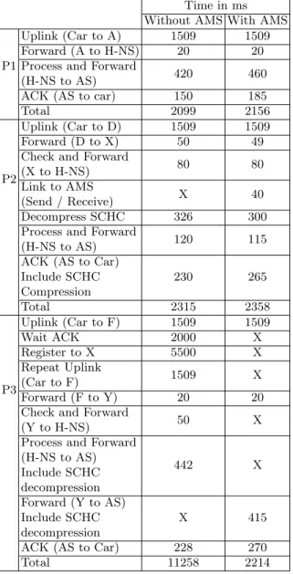
Table 1. Measurements of the latency Time in ms Without AMS With AMS
P1
Uplink (Car to A) 1509 1509
Forward (A to H-NS) 20 20
Process and Forward
(H-NS to AS) 420 460
ACK (AS to car) 150 185
Total 2099 2156
P2
Uplink (Car to D) 1509 1509
Forward (D to X) 50 49
Check and Forward
(X to H-NS) 80 80
Link to AMS
(Send / Receive) X 40
Decompress SCHC 326 300
Process and Forward
(H-NS to AS) 120 115
ACK (AS to Car) Include SCHC Compression 230 265 Total 2315 2358 P3 Uplink (Car to F) 1509 1509 Wait ACK 2000 X Register to X 5500 X Repeat Uplink (Car to F) 1509 X Forward (F to Y) 20 20
Check and Forward
(Y to H-NS) 50 X
Process and Forward (H-NS to AS) Include SCHC decompression 442 X Forward (Y to AS) Include SCHC decompression X 415
ACK (AS to Car) 228 270
SCHC-Based Solution for Roaming in LoRaWAN 9
to use a payload size of 155 bytes, the Spreading Factor (SF) is set to 10 and the bandwidth is set to 125 kHz. The payload of 155 bytes consists of 40 bytes representing uncompressed IPv6, 8 bytes for UDP, 4 bytes for CoAP, 1 byte for RuleID, 1 to 5 bytes for compression headers, and remain bytes are data.
3.1 At position P1
In the P1 position, as shown in figure 3, the car is under the coverage of GW (A). As shown in Table 1 and Figure 4, the car sends an uplink message to GW(A). Then, the uplink message is forwarded to the H-NS. In a network not compatible with AMS, the H-NS unpacks the package, then decompresses it and sends it to the AS. While, if AMS is supported, H-NS sends the packet to AMS to decompress it. Then, H-NS forwards this packet to AS. The additional time delay between the two implementations is the time needed to send and receive the packet between H-NS and AMS. As shown in Table 1 and Figure 4 in P1, without AMS, in the downlink when the AS returns an acknowledgment, H-NS compresses the downlink with a duration of 150 ms. But a communication time delay of 185 ms is added to compress the headers when AMS is used. Finally, the total time difference between AMS network support and the non-AMS network is 57 ms. This additional cost represents the link time between H-NS and AMS generated during the uplink and the downlink to achieve a complete communication procedure. Our proposal will add a time delay of 57 ms in the uplink during decompression and in the downlink during compression of the packet headers over the current implementation of LoRaWANv1.1. But with AMS, the context of SCHC is centralized within a server and avoids the dispersion of the ED context between the servers. In addition, technologies such as LoRaWAN are not developed for the use of applications in real time, so that 57 ms of latency will not be recognized.
3.2 At position P2
In the P2 position, as shown in Figure 3, the car is under the coverage of GW(D). As shown in Table 1 and Figure 4, the car sends an uplink message to GW(D). This uplink message costs 1.50938 seconds of time. Then, GW(D) forwards the received LoRaWAN frame to V-NS(X). The link between GW(D) and V-NS(X) costs 50 ms to forward the received LoRaWAN frame. Since the collaboration with the H-NS is passive, the V-NS(X) verifies only the address of the device at the L2 layer and sends the LoRaWAN frame back to the H-NS. This procedure costs 80 ms which this depends on the process of the Raspberry Pi (RPi) and the link between the two RPis. In a LoRaWAN network without AMS, H-NS has the SCHC context of the device to decompress the headers of received pack-ets. This process costs 326 ms. While in our proposal the network is compatible with AMS, it maintains the SCHC context of the device and decompresses the packet header. The cost of the link between H-NS and AMS is 40 ms for send-ing/receiving and 300 ms to decompress the package. Finally, the H-NS receives the decompressed header packet and sends it to AS with a time delay of 120
ms. After a successful uplink message is received, the AS will respond with an ACK in the downlink message. In the LoRaWANv1.1 network, the total latency for a complete procedure was 2,315 seconds, whereas it is 2,358 seconds for the network with AMS. The results show that in the case of passive collaboration, our proposal is not so much time consuming and improves the organization of the compression/decompression of SCHC in the network in a central server.
3.3 At position P3
In the P3 position, as shown in Figure 3, the car is under the coverage of GW(F). As shown in Table 1 and Figure 4, the car sends an uplink message to GW(F). In the network without the AMS, the GW forwards the received frame to V-NS(Y). Since collaboration is handover, the LoRaWAN frame is dropped and the device has to register with the V-NS(Y). As shown in Figure 4, the car waits two seconds to receive an ACK, but the frame was dropped. Without receiving confirmation, the device detects a loss of connection. Therefore, as shown in Table 1 and Figure 4 for the position P3 without AMS, the total time delay is 1,509 for the uplink and 2 seconds are waiting for an ACK. Then, the device begins with the registration procedure with the V-NS(Y) [10]. The registration procedure OTAA costs 5.5 seconds in our case. Then, the device repeats the uplink message with a time delay of 1.509 seconds. After that, the V-NS(Y) forwards the packet to H-NS. Then, the packet is sent to AS after decompressing the headers. While for the network that supports AMS, a preregistration process is performed on the V-NS(Y) by the AMS. This mechanism prevents dropping the uplink message as shown in Figure 4 at P3 with AMS. Moreover, when using the AMS, the following packets received from the device can be decompressed directly by sending to AMS. This mechanism adds a time delay between the V-NS(Y) and the AMS but reduces the time delay between V-NS(Y) and H-NS. Then, the packet is sent directly to AS by V-NS(Y). This proposal also saves the cost of routing, especially if AS and V-NS(Y) are in the same network topology. In addition, it saves the use of bandwidth between V-NS(Y) and H-NS, and between H-NS and AS, as the number of devices belonging to H-NS increases. Finally, as shown in Table 1 and Figure 4, the total time cost of the network without AMS is 11.258 seconds to deliver the first uplink from the device to AS, while for a network with AMS, the uplink message is delivered to AS with only 2,214 seconds.
4
CONCLUSIONS
In this paper, the LoRaWAN architecture is modified by adding an AMS to improve the mobility of the device; uses an IPv6 header compressed by SCHC. We implemented the AMS mechanism in a testbed to verify the improvement in term of time. The contributions of AMS were: decreases the time to handle the uplink message before the registration process during the LoRaWAN handover collaboration. Secondly, it saves the bandwidth and message rate of the device
SCHC-Based Solution for Roaming in LoRaWAN 11
and avoids repeating the transmission and avoids transmitting the SCHC context of the device to the new NS. Third, reserve the power of the device by avoiding repeating the uplink messages. On the other hand, improve the transfer and continuity of the session in layer L3 as shown in [3]. Fourth, it improves the use of the SCHC protocol and saves the bandwidth from context exchange and the updates. Finally, it avoids the dispersion of the SCHC context saved in different NS during each movement of the device.
References
1. Lora alliance, [Online], https://www.lora-alliance.org/, Accessed on 06 Oct 2018 2. Ayoub, W., Samhat, A.E., Nouvel, F., Mroue, M., Pr´evotet, J.: Internet of
mo-bile things: Overview of lorawan, dash7, and nb-iot in lpwans standards and supported mobility. IEEE Communications Surveys Tutorials pp. 1–1 (2018). https://doi.org/10.1109/COMST.2018.2877382
3. Ayoub, W., Nouvel, F., Hmede, S., Samhat, A.E., Mroue, M., Pr´evotet, J.C.: Im-plementation of SCHC in NS-3 Simulator and Comparison with 6LoWPAN. In: 26th International Conference on Telecommunications (ICT). HANOI, Vietnam (Apr 2019), https://hal.archives-ouvertes.fr/hal-02051757
4. Baharudin, A.M., Yan, W.: Long-range wireless sensor networks for geo-location tracking: Design and evaluation. In: 2016 International Electronics Symposium (IES). pp. 76–80 (Sep 2016). https://doi.org/10.1109/ELECSYM.2016.7860979 5. Botelho, R., Souza, L.O.O., Pingle, J., Dillard, J., Beaver, S., Smith, M.: Open
source security firewall from netgate, https://www.pfsense.org/, Accessed on 5 Feb 2019
6. Cablelabs, Sidnfonds, Acklio: Loraserver project, https://www.loraserver.io/, Ac-cessed on 5 Feb 2019
7. Fargas, B.C., Petersen, M.N.: Gps-free geolocation using lora in low-power wans. In: 2017 Global Internet of Things Summit (GIoTS). pp. 1–6 (June 2017). https://doi.org/10.1109/GIOTS.2017.8016251
8. Kooijman, M.: Arduino-lmic library, https://github.com/matthijskooijman/arduino-lmic, Dec 5, 2017
9. LPWAN-IETF-WG: Lpwan static context header compression (schc) and fragmen-tation for ipv6 and udp, https://tools.ietf.org/html/draft-ietf-lpwan-ipv6-static-context-hc-09, Accessed on Dec. 22, 2017
10. Toussaint, J., Rachkidy, N.E., Guitton, A.: Performance analysis of the on-the-air activation in lorawan. In: 2016 IEEE 7th Annual Information Technology, Elec-tronics and Mobile Communication Conference (IEMCON). pp. 1–7 (Oct 2016). https://doi.org/10.1109/IEMCON.2016.7746082