HAL Id: hal-02382302
https://hal.laas.fr/hal-02382302
Submitted on 2 Dec 2019HAL is a multi-disciplinary open access archive for the deposit and dissemination of sci-entific research documents, whether they are pub-lished or not. The documents may come from teaching and research institutions in France or abroad, or from public or private research centers.
L’archive ouverte pluridisciplinaire HAL, est destinée au dépôt et à la diffusion de documents scientifiques de niveau recherche, publiés ou non, émanant des établissements d’enseignement et de recherche français ou étrangers, des laboratoires publics ou privés.
Synchronizing Activities and Products through State
Transitions
Amal Rochd, Maria Zrikem, Thierry Millan, Christian Percebois, Claude
Baron, Abderrahmane Ayadi
To cite this version:
Amal Rochd, Maria Zrikem, Thierry Millan, Christian Percebois, Claude Baron, et al.. SynchroState: A SPEM-based Solution for Synchronizing Activities and Products through State Transitions. In-ternational Arab Journal of Information Technology, Colleges of Computing and Information Society (CCIS), 2018, 15 (6), pp.951-961. �hal-02382302�
SynchroState: A SPEM-based Solution for
Synchronizing Activities and Products through
State Transitions
Amal Rochd
1, Maria Zrikem
1, Thierry Millan
2, Christian Percebois
2, Claude Baron
3, and Abderrahmane
Ayadi
11
Laboratory of Modeling and Information Technologies, University of Cadi Ayyad, Morocco
2Institut de Recherche en Informatique de Toulouse, Université de Toulouse, France
3Laboratoire d’Analyse et d’Architecture des Systèmes, Université de Toulouse, France
Abstract: Software engineering research was always focused around the efficiency of software development processes.
Recently, we noticed an increasing interest in model-driven approaches in this context. Models that were once merely descriptive, are nowadays playing a productive role in defining engineering processes and managing their lifecycles. However, there is a problem that has not been considered enough; it is about sustaining consistency between products and the implicated activities during the process lifecycle. This issue, identified in this paper as the synchronization problem, needs to be resolved in order to guarantee a flawless execution of a software process. In this paper, we present a SPEM-based solution named SynchroState that highlights the relationship between process activities and products. SynchroState's goal is to ensure synchronization between activities and products in order that if one of these two entities undergoes a change, the dependents entities should be notified and evolved to sustain consistency In order to evaluate SynchroState, we have implemented the solution using the AspectJ language and validated it through a case study inspired from the ISPW-6 software process example. Results of this study demonstrate the automation of synchronization of product state following a change in the activity state during the evolution of the process execution.
Keywords: Synchro state, SPEM, metamodeling, process model, synchronization, aspectJ.
Received April 17, 2015; accepted June 9, 2016
1. Introduction
The evolution of economy on an international scale requires companies and other organizations to adopt efficient and adaptable logistic support and information systems. This need was behind the effort of software engineering industry to identify and define time-to-market efficient methods and processes allowing the design and development of high quality software in respect of defined deadlines and limited budget. The increasing complexity of these software products has led the computing community to master the software development process and to implement tools for high productivity development.
These factors are transforming software engineering process into socio-cultural activity requiring the management of activities distribution over
geographically dispersed teams working
simultaneously on the same project.
Software process modeling was emerged to address these concerns. The first attempts to model processes were with informal languages, such as life cycle models [20]. The advantage of automation appears clearly with the use of executable language for the representation of process. Thus, several studies [6, 18, 21, 32] have been conducted in order to design Process
Modeling Languages (PMLs) [34].
One particular problem in this context is that of maintaining consistency of the different artefacts during software engineering process. In fact collaboration can only be efficient if there is a mechanism to ensure the consistency of the shared software components and the propagation of the changes the specifications and requirements undertake. While advanced software architectures such as Service Oriented Architecture (SOA) are essentially based on the separation of concerns, there will always be transversal and shared software components that create dependency between the different activities of software engineering process. We thus need a dedicated mechanism keeping track of the evolution of all involved activities and propagating the different changes in order to update products states and ensure a real-time synchronization of activities and products states.
This paper presents our solution to this particular problem. This solution, named SynchroState extends the Software Process Engineering Metamodel (SPEM) [25], and borrows concepts of Unified Modeling Language (UML) 2.0 [26], to address the problem of synchronization between activities and products in a software development process, i.e., the ability to
propagate changes from one activity to the activities/products that depend on and vice versa. SynchroState extends SPEM metamodel, to represent development processes and their components. Moreover, it integrates UML state machines metamodel to represent the state changes of activities and products. The Observer design pattern, on its side, was used to capture these state changes and process them as events.
These three key elements were incorporated in one whole metamodel to ensure process synchronization.
This paper is organized as follows: the next section presents a state of the art on the SPEM metamodel and its implementations. The third section is devoted to present our proposed solution of synchronization between activities and products within a software development process. The solution comes in the form of a metamodel named SynchroState. In this section, we describe the general architecture of the metamodel, as well as its details and semantics. Section 4 is dedicated to present the implementation and validation of our solution. The implementation was elaborated based on an aspect oriented approach, using the AspectJ language, and validated through a case study inspired from the 6th International Software Process
Workshop (ISPW-6) software process example [17]. A related work description is provided in section 5. The paper is concluded with a summary of the performed work, and gives different perspectives that we expect for the rest of our work.
2.
State of Art: Software Process Engineering
Metamodel
SPEM [25] is a metamodel proposed by the Object Management Group (OMG) that describes the software production processes. Its objective is to provide tools and concepts to model, document, present, manage and make development methods concrete. SPEM is based on UML by extending it in the form of an UML profile.
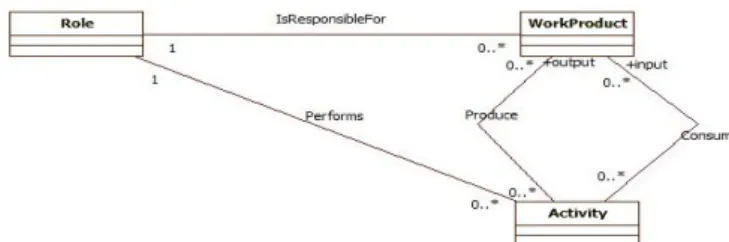
SPEM defines a software development process as a collaboration between roles that perform activities; these activities consume products as inputs and produce others as outputs, as it is represented by the conceptual model in Figure 1. It also gives a description of the model content it defines. It is therefore a separation of the structure of the process and its content.
Figure 1. Conceptual model of software process engineering metamodel.
SPEM is structured into seven main packages associated with merge mechanism [25]. In what follows, we present a summary of the content of each package of SPEM:
Core: the core package contains the basic elements (in the form of UML class) used in all other packages. The WorkDefinition class constitutes the breakdown structure of this package and it generalizes all work activities of SPEM2.0.
Process structure: this package describes the basics of design for all models. It defines the elements used to represent process models in terms of flow of activities (Activities) with their use of products (Work Product Uses) and roles (Role Uses).
Process Behaviour: this package provides a means of linking an element of SPEM2.0 process with an external behavioral model such as UML 2.0 Activity Diagram.
Managed content: this package provides the concepts for managing textual descriptions either independently or in combination with the concepts of process structures. Examples of such concepts are
ContentDescription and Guidance classes.
Method content: this package provides concepts that allow the development of a knowledge base independent of a process or a particular project, such as Roles, Tasks and WorkProducts.
Process with methods: this package is used to define the required elements to integrate processes designed with the concepts of the ProcessStructure package, with an instance of Method Content package.
Method plugin: this package provides the metamodel concepts used to design and manage reusable and configurable methods, process libraries and repositories.
The OMG proposes two methods for describing the execution of a SPEM process model:
The first method is to set the sequencing between the process activities, and assign documentation to each activity, in order to develop a definition and a project planning [27]. This method suffers from the lack of control over the assignment of roles to resources, since SPEM does not define any relationship between roles and resources of a process. It does not provide a means to monitor the status of the products after each activity. Therefore, this approach cannot be considered as a solution of SPEM executability.
The second method consists on establishing a link between the elements of SPEM process model and an external behavioral model. For example, one can describe a process with an UML activity diagram, and then make the link between the process elements and their equivalents in the chosen model. Similarly, this approach has several shortcomings.
In fact, SPEM gives no description of the method of connection between its components and the chosen behavioral model. Furthermore, the behavioral models are richer in terms of concepts than SPEM 2.0. So, it is possible that changes made on the behavioral model can not be transformed to the SPEM process model, which leads to the problem of traceability of changes.
Because of the gaps in these implementation methods, many studies have been devoted to the resolution of these problems, as xSPEM [4] and UML4SPM [3], but none of them has addressed directly the issue of synchronization of products and activities within a software development process.
Thus, our work is to study the impact of the spread between products and activities states on the execution of a software development process. In the next section, we present our proposed solution to the problem of synchronization through a metamodel named SynchroState.
3. The Synchronization Solution
3.1. General Architecture
SynchroState metamodel is based on SPEM 2.0, UML 2.0 and an Observer design pattern metamodel [12].
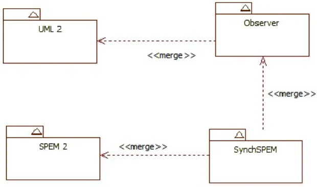
SPEM 2.0 and UML 2.0 respectively provide support for the description of a process and support for state machines and events. On the other hand, the Observer design pattern metamodel provides a standardized implementation of a solution to define interdependence of one to many, so that when an object state changes, all those who depend on it are notified and automatically updated [14]. The SynchroState solution offers new concepts for synchronizing the various artefacts of a process. Therefore, SynchroState is a compatible extension with the SPEM 2.0 standard of process representation. Figure 2 represents the general architecture of our metamodel.
Figure 2. General architecture of synchro state.
We propose here to present the Observer metamodel exhaustively described in [12]. From the solution proposed by Favre [12] including an implementation of the design pattern through interfaces, we only keep, for simplicity of speech, the class diagram showing the communication links between an observer and an
observed subject. The association between ConcreteSubject and Property, initially proposed, was replaced by an association between ConcreteSubject and StateMachine. In our approach, it is essential to implement a mechanism to orchestrate the evolution of status changes. The use of a simple link between ConcreteSubject and an attribute (property) only allows to keep the name of the current state and not to exploit the possibilities of UML 2.0 to represent the state transition diagrams. We thus have opted in this approach to connect the ConcreteSubject class through the state role to a StateMachine that provides automatic support for all the states and transitions of a ConcreteSubject. This state role may be an instance of StateMachine of UML 2.0 metamodel or an instance of a class that inherits from StateMachine. We made the choice to consider the State role as an instance of StateMachine according to UML 2.0.
3.2. Detail and Semantics
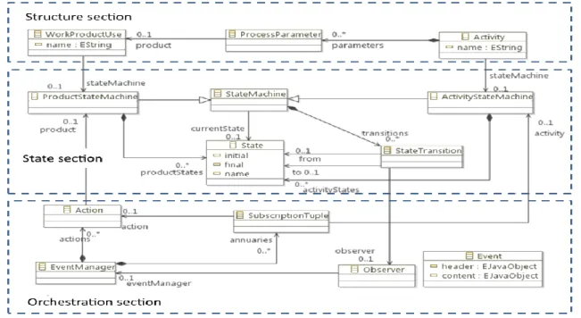
SynchroState is an extension of SPEM 2.0 that aims to represent the fact that the activities and products are synchronized during the process execution. It merges concepts and elements of SPEM 2.0 and UML 2.0 architecture and organizes its own elements and entities as shown in Figure 3.
SynchroState architecture is divided into three main sections:
Structure: a process consists of a set of activities (Activity) and products (WorkProductUse) in relation with each other. SPEM defined the relationship between these two entities through the ProcessParameter entity. The structure section of SynchroState is simply a resumption of the relationships between activities and products proposed by SPEM. This section is not polluted by any external concept to SPEM.
State: this section describes the states of Activity/Work Product Use entities and their transitions. This is achieved with the introduction of a simplified state machine metamodel as described in the UML specification. It allows representing a multi-state object through its transitions. Each product/activity state machine keeps track its current status. This section triggers the orchestration mechanism through the notify method on the transition that must operate the observation mechanisms.
Orchestration: this section is much more behavioural; its life cycle begins with the invocation of the Observer by the transitions, the observer then triggers the spread by contacting the EventManager which holds a directory of activities and products couples in the form of SubscriptionTuple instances. Once a receiver is selected, the message is sent, the actioner must then proceed to the alteration of the product state.
Figure 3. Detailed architecture of synchro state.
In what follows, we give the details of the elements composing SynchroState:
SynchroState inherits from SPEM 2.0, and more specifically from WorkProductUse, Activity, and ProcessParameter classes of the ProcessStructure package. The structure proposed by SPEM between activities and products through the ProcessParameter entity was kept.
For the activities and products, we defined the ProductStateMachine and ActivityStateMachine entities that specialize the StateMachine class of UML 2.0. This metaclass is derived from the UML 2.0 metamodel and more specifically from its BehaviorStateMachines package. It represents the state machine of the entity to which it is linked. To capture only the changes of states, this automaton must consist of simple states and contain a region composed of simple states. In addition, only transitions of SynchroTransition type are permitted. The SynchroTransition class represents a transition that has as single action the call for a method that inherits from the notify operation defined for an instance of the ClassSubject metaclass. This class inherits from the Transition class derived from the UML 2.0 metamodel and from the same BehaviorStateMachines package.
Transitions will be automatically captured and generate the desired event to begin the orchestration lifecycle.
The StateMachine association specifies the automaton describing the set of states and transitions
supported by SynchroWorkProduct and
SynchroActivity. It may be an instance of StateMachine or an instance of a class that inherits from StateMachine. This role inherits from ConcreteSubject::state of the Observer metamodel.
For each state machine, we have the list of possible states (represented by productStates and
activityStates), and transitions between these states represented by the StateTransition class, as well as the current state represented by the currentState association.
An actioner is associated to each Product state machine. The actioner allows influencing an object on the basis of the state changes of the object on which it depends, without interrupting its flow of execution. This is a non-intrusive way that will change the state of the product without requesting it or bring it out of its normal flow of execution [22].
To explain this interaction, we will refer to the following scenario: a change in the state of an activity lead to the trigger of the transition (StateTransition), an instance of Event is thus created with the identifier of the activity as header and the new status as content.
This instance is observed by the orchestration mechanism which takes the event, analyses it, selects the dependent objects (ProductStateMachine) and forwards the event to their respective actioners. These ones will take care of forcing transitions to coherent states with the initial change.
4. Implementation and Validation
The objective of this section is to present the implementation of SynchroState on a case that will demonstrate the propagation of the state change of the activity to different dependent products.
The achievement of the synchronization solution cannot have a practical industrial value only if we can simulate its behaviour on a case study. In this context, we propose a validation that consists of the development of a computing solution that resumes the functioning of the orchestration engine and its validation through a case, in order to monitor the execution trace. This step will allow us to highlight the
real transitions and propagation of synchronization events throughout the life cycle of the orchestration.
The implementation of the metamodel has been achieved using Eclipse Modeling Framework (EMF).
EMF [10, 33] is a modeling framework and code generation facility for specifying metamodels, managing models instances, and building tools and other applications based on a structured data model. EMF is a Java implementation of the Ecore meta model [2, 9] which is similar to the MOF standard.
We note that, in order to implement SynchroState metamodel, we represented it in the form of an Ecore diagram and presented it according to two different concerns. The first concern is the description of the software design artefacts through various entities representing the products, the activities and their links through parameters classes and their respective state machines. While the second concern relates to the activity of orchestration and synchronization and the different classes that can meet this need by their functioning during a process instance. In what follows, we will refer to the first part by the term Structural section and the second part by Behavioural section.
4.1. Structural and Behavioural Section
The process structure involves the description of the various components that constitute it and the relationships between them. The structural part in the SynchroState model is constituted of:
Activity classes: Activity and Activity State Machine.
Product classes: Work Product Use and Product State Machine.
The intermediate class between activities and
products: Process parameter.
The metamodel classes of state machines: StateMachine, State and StateTransition.
This structural section allows us to consolidate our idea of control and orchestration through state changes.
However, it does not allow us to highlight the orchestration procedure during the execution of a process instance. This is ensured in the behavioural section.
Behavioural section is not linked with the structure of the engineering process. It considers, in an abstract way, two behaviours:
The subscription of an object (A) to receive events from an object (B).
The propagation of an event from the object (B) to the object (A).
This section completes the structure by exposing the various entities responsible for the propagation of the event.
We distinguish the Observer entity that captures the state transitions and contacts the EventManager to
select the corresponding receivers, through the subscription of products to activities, and send the event to the actioners responsible of altering the state of the product accordingly.
In what follows, we will explain the implemented mechanisms to ensure consistency between these two sections and perform the orchestration.
4.2. Orchestration by Aspects
The implementation should not be done to the detriment of the integrity of the metamodel, especially the structural section, and should therefore be included in a non-intrusive way. Indeed, a hard-integration mechanism will compromise the abstract and general aspect and will constrain the process according to a given selection process.
In this context, we propose the use of the Aspect-Oriented Programming (AOP) [28] as non-intrusive means to create connections between the different components of the metamodel and provide automation support.
Aspect-oriented programming is a paradigm that allows the injection of transverse behaviour during the execution of a software component. By transverse behaviour, we mean any set of instructions invoked in different components and layers of software and that compromise the separation of concerns [13]. We cite as an example, the different logging instructions that allow to trace the various functions calls and errors tracing, without any constraint of separation between software components and layers. For the implementation of these aspects, we have chosen to use AspectJ [1]: an aspect weaver independent of any framework and non-intrusive in the source code of the application.
AspectJ is an extension to Java that provides additional keywords for AOP concepts. AspectJ defines aspects accompanied by their integration rules that are expressed in the form of pointcuts. It also provides a process for weaving aspects with business services of the application, so that the behaviour of an aspect is triggered at all points where this aspect is applicable. AspectJ is among the first aspect-oriented languages and it holds great potential [1, 19]. This language has already been tested in a similar context, which concerns automating the monitoring of process execution in systems engineering [16].
4.3. Implementation and Validation
The implementation of the orchestration layer proceeds as follows: for each participating entity in the synchronization lifecycle, we propose to create an aspect which is responsible for controlling the invocation of the relevant class and to perform the required processing. In general, each aspect proceeds by the following steps:
Reception of the invocation event.
Interpretation of input data.
Selection of the receiver entity and communication of results.
All these activities occur in different aspects, even if the methods invoked in the metamodel classes represent only empty shells, aspects behave as joints for the structure of the process.
To highlight this implementation, we will present the various implemented aspects and their respective roles in the order of their invocations:
Activity: the execution of an activity is our starting point. Thus, the Activity class is provided with an empty method called perform () that represents the work to be performed. The ActivityAspect aspect captures the invocation of this method and performs outside of model classes, the necessary actions. At the end of the execution, this aspect invokes the state change in the ActivityStateMachine state machine.
Activity state machine: the reception of a state change event (empty method alterState ()) automatically triggers the ActivityStateAspect aspect which begins by considering the current state, the nature of the invocation and takes the decision to choose the next state of the activity. Then, it invokes the corresponding observer.
The observer: the observer receives state change notifications from the activities state machines. Once notified, the ObserverAspect aspect is automatically triggered, its role is to create an event that includes the sender as header and the new state of the activity as subject and transmit it to the event manager.
The event manager: when invoking the manager, its aspect EventManagerAspect takes control. Its role is to check the couples of available subscriptions, then in the basis of the dispatching activity, choose the receivers among the products actioners (Action) and communicate the event object to them.
Actioners: the actioners are invoked through the empty method triggerAction(). The execution of this method triggers the ActionAspect aspect that interprets the received event (state change of an activity) and takes the decision to change the state of the product accordingly.
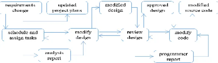
Our case study consists in the example of the development process described in Figure 4. This process was inspired and described by the famous example of software process ISPW-6 [17]. It consists of four activities: schedule and assign tasks, modify design, review design and modify code. Each of these activities takes as input products, and produces others.
Figure 4. Example of a development process.
For each activity, we defined three states: ready, in progress and achieved, while the products take the states: unavailable and available. The general logic is to illustrate that the dependent project must transit automatically from the unavailable state to the available state, at the end of the execution of the activity. This example is intended to underscore the monitoring of the execution trace and the actual invocations of different aspects.
From now on, we shall use the term Aspect (with a capital A) for AspectJ's aspects to avoid any misunderstanding.
In order to examine the execution process, we shall present the content of each Aspect through a graphic flow chart representing its algorithm. We shall represent the behaviour of the aspect without showing the corresponding class for the sake of clarity.
Synchro process aspect: the execution life cycle
starts with the SynchroProcessAspect. This aspect is in charge of checking which activities are ready to trigger and proceed with the execution. We can consider it as an entry point to the execution. Its behaviour is described in the flowchart of Figure 5.
Figure 5. Flow execution of synchro state process aspect.
The algorithm starts with initializing the activities list with the content of the model and preparing the stopping conditions (the number of finished activities equals the number of available activities). The algorithm keeps checking for available activities as long as this condition is not yet met. Each time an
activity is executed, it results with the change of its output products to their final state, and, by doing so, they become available to other activities to be triggered. The hidden risk is that the user did not check for deadlocks in his model, i.e., a situation where input products keep unavailable whatever activities are executed.
For each activity, we check the availability of all its input products. In case these products are available, we proceed to trigger the activity, and then we mark it as done, as a mean to update the stopping condition.
We should stress at this level that triggering the activity is done by summoning its method trigger and not directly its aspect. The aspect will be automatically summoned through the execution of the target method.
Activity aspect, Activity state aspect and TransitionAspect: once an activity triggered, it
executes its inner operations and then summons its state machine in order to alter its state. The state machine (through the algorithm of its Aspect) checks for the next state then triggers the transition.
TransitionAspect does nothing but encapsulates the
details of the transition, i.e., the concerned activity and the state, and summons the observer to start the synchronization process.
Figure 6 shows the details of these steps through a flow chart.
Figure 6. Lifecycle of an activity state change.
Orchestration lifecycle: the orchestration process starts at this point. The first thing the observer does is summon the event manager to check for every
ProductAction subscribed to the encapsulated
activity. In fact, the EventManager has a set of
TupleSubscription that contains mapping between
output products and their producing activities. As soon as the EventManager selects the concerned Actions, it sends the encapsulated message (Activity and new state) to each action in order to trigger Product state change.
Figure 7 shows the orchestration lifecycle as a flow chart.
Figure 7. Orchestration life cycle.
Product state aspect: at this point, we are at the end of the activity execution lifecycle. The
ProductStateAspect receives the directives from the ActionAspect and proceeds with changing the
product's state.
If the product is switched to its final state and becomes available, it will update the process by making dependent activities ready.
We established posts at each aspect to trace execution. We propose Figure 8 the execution trace in the console.
Figure 8. The execution trace.
The execution trace shows the routing in accordance with the life cycle of the orchestration stated earlier in this paper. Thus, we can notice the activities state change that led to the trigger of the event at the level of the observer. We also note the three steps of event routing at the level of the EventManager. It is at this level that we can confirm the ability of the mechanism to handle cases with multiple activities and products through the directory of activity-product subscription.
Even though the solution was validated through a case study inspired from the ISPW-6 [17], there are, however, threats to its validity. The first point of concern is the linearity of software engineering process as considered by SynchroState. In fact, the solution
should be aware of the complication introduced by collaboration among actors with different cultural and technical backgrounds. This diversity opens software engineering projects to multiple threats originating from the misinterpretation of requirements and the development of misaligned products and services. In this context, we intend to manage this threat by integrating process test and validation mechanisms inside the core engine of the solution, in order to provide a test driven engineering environment allowing us to react in time to such problems.
Another significant threat resides in is the sample size of the study case. This study had only four activities, while in real world it could be more, and especially in the case of large complex projects. This parameter raised the possibility that we would not be observing real-world software development behaviours with their attendant complexities. The case study that we used is applicable to laboratory settings but not necessarily representative of real-world software development processes. To address this threat, we are currently attempting full-scale case study in order to have deep perception of SynchroState relevance in a professional setting in the future.
5. Related works
The main contribution of this paper is to provide synchronization support to software development processes. Our choice of SPEM is based on the fact that it provides support for the systematic development and management of development processes as well as for the adaptation of processes to specific project context [24]. SPEM’s ability to separate content from structure and its semantic richness made it the basis of many modern software engineering approaches, such as xSPEM [4], UML4SPM [3], eSPEM [11]. These solutions focus on the execution of SPEM based models, and do not deal with the synchronization problem within software development processes.
This synchronization problem is generally identified in systems engineering processes. In fact, there are some interesting works on the subject such as using Data-driven Process Structure in order to manage dependencies between the elementary processes participating to the engineering project.
In [23], the authors give the example of adding or removing a component from the system, this information has to be broadcasted to the different sub-processes in order to be taken into consideration and to adapt accordingly. This synchronization is performed at runtime which makes the proposed solution practical and enhances its added value. In our proposed solution, we propose to go even deeper and to apply synchronization for each state transition of activities and products in the distributed software engineering process.
We should mention that we are considering the synchronization problem during the software engineering process execution. Yet, there is another approach to this problem: Considering flexible software architecture able to deal with changes in specifications and requirements of its different components. There are in fact some significant works that focuses on the structure of the software through the definition of basic (or even atomic) collaborative software components and the identification of a model to manage their evolution during runtime. One significant work in this context is the definition of Living models in the context of change driven software engineering [7]. Even if this approach seems focusing on the after development phase of software engineering, it can have a great impact on our problem, through minimizing the complexity of each component and considering the final product as the collaboration of multiple micro services, then the approach of change-driven engineering will be of good use in order to minimize the impact of specifications change. Still this solution doesn't address the main problem of this paper: The ability to manage change during software engineering process through synchronizing the states of the different activities and products.
Nevertheless, in a former work, we presented a solution to the synchronization problem named Synch SPEM [29, 30, 31]. SynchSPEM uses the holonic paradigm [5] in order to define products and activities states as the different variations of the structural and informational properties values. The main objective of this approach is to provide a quantifiable way to assess state transitions within a product or activity through evaluation of structure and content. The mapping between activities and products is insured through an abstract mechanism named CheckListMatrix that is used in order to check compliance of activities to products. This entity has been provided as a guideline presenting the dependencies between activities and products based on their production/consumption relationships. SynchSPEM is related to SPEM through merging the structural packages and the content packages separately. State changes are captured through the definition of events; these events are analysed through the CheckListMatrix in order to decide which products have to be updated. The process of propagation of the state transition is part of an overall automation mechanism called orchestration. This mechanism has been designed and developed using Kermeta [8] metamodeling language and its aspect oriented programming abilities.
Our work on SynchSPEM showed us that the key point to synchronization is to identify and manage state definition and state transition of activities and products. In this context, we choose to focus our work on this feature and return to a more simple representation of the process, we then abandoned the holonic representation of the elements structure and
content, in order to hold a unified view of the process through merging WorkProduct and Activity concepts, and provide a simple process definition view expressing the relationship between activities and products as defined in SPEM. We also enhanced the representation of elements states through a full integration of the state machine model linked to products and activities in order to trace their respective transitions. The structure of the orchestration mechanism is a part of the whole metamodel and its automation is insured through a non-intrusive software layer developed through the AspectJ programming language.
Lastly, while the former approach, SynchSPEM, is based on the detection of state transitions through separating structure from content and evaluating their respective properties, SynchroState uses a more practical way by defining state machines that monitor activities through aspect oriented mechanisms. On another hand, the SynchroState fully integrates the synchronization mechanism inside the metamodel, while in SynchSPEM, it was presented as an outside mechanism designed and developed using Kermeta language.
6. Conclusions
Software engineering is becoming more and more aware of the importance of optimizing the various processes and activities involved in the product implementation. In this context, many works have focused on modeling concepts, partial or total automation of some processes, the execution control, and consistency insurance through synchronization.
We propose in this paper a solution to the problem of synchronization between activities and products within a software development process, called SynchroState. SynchroState is a metamodel that extends SPEM 2.0, while integrating key concepts of UML 2.0. Its objective is to ensure that any state change of an activity should be routed to its input and output products. Similarly, any change in a product should be noticed by the activities that depend on it.
This synchronization effort is highly important as it ensures the consistency of the engineering process. We implemented the solution using EMF and provided automation through integrating aspect oriented mechanisms as articulations, to this end we used AspectJ language.
This implementation allowed us to validate the solution by running it on a process example. The execution of this case study showed the propagation of state transitions from activities to products and the ability of the solution to keep process consistency through updating the process components.
To the best of our knowledge, there is currently no other research work that deals with the synchronization problem except for our former work SynchSPEM that
deals with the issue of capturing activities state transitions and propagating changes from activities to products in order to avoid deviations during software development process. However, SynchroState represents a more elegant solution to the synchronization problem that integrates structure and automation in one whole metamodel.
Currently, we are working on the integration of SynchroState into a software project management tool plugged into integrated development environments in order to provide a high level process control and monitoring.
We are also working on the interoperability with another process engineering modeling solution named SysPEM [15, 16] developed in the context of systems engineering. SysPEM allows describing process concepts and controlling the execution flow. Our objective is to find a way to interface SynchroState with SysPEM in order to enhance its ability to validate products requirements through synchronization.
References
[1] Apel S. and Batory D., “How AspectJ is Used: An Analysis of Eleven AspectJ Programs,”
Journal of Object Technology, vol. 9, no. 1, pp.
117-142, 2008.
[2] Bánfai B., Ulrich B., Török Z., Natarajan R., and Ireland T., “Implementing an HL7 Version 3 Modeling Tool from an Ecore Model,” in
Proceedings of Medical Informatics in a United and Healthy Europe, Washington, pp. 157-161,
2009.
[3] Bendraou R., Gervais M., and Blanc X., “UML4SPM: An Executable Software Process Modeling Language Providing High-Level Abstractions,” in Proceedings of 10th IEEE
International Enterprise Distributed Object Computing Conference, Hong Kong, pp.
297-306, 2006.
[4] Bendraou R., Combemale B., Crégut X., and Gervais M., “Definition of an Executable SPEM 2.0,” in Proceedings of 14th Asia-Pacific Software Engineering Conference, Aichi, pp.
390-397, 2007.
[5] Bendriss S., Benabdelhafid A., Boukachour J., and Boudebous D., “Métamodèle de Référence Holonique Pour La Gestion De La Traçabilité Du Produit Dans La Chaine Logistique,” in
Proceedings of 5ème Colloque International Conception et Production Intégrées, 2007.
[6] Borgonon L., Barcelona M., García-García J., Alba M., and Escalona M., “Software Process Modeling Languages: A Systematic Literature Review,” Information and Software Technology, vol. 56, no. 2, pp. 103-116, 2014.
[7] Breu R., Agreiter B., Farwick M., Felderer M., Hafner M., and Innerhofer-Oberperfler F.,
“Living Models-Ten Principles for Change-Driven Software Engineering,” International
Journal Software and Informatics, vol. 5, no. 1-2,
pp. 267-290, 2011.
[8] Drey Z., Faucher C., Fleurey F., Mahé V. and Vojtisek D., Kermeta Language Reference Manual, Manuscript available online http://www.kermeta.org, Last Visited, 2015.
[9] Eclipse.org, EMF Java doc.
http://download.eclipse.org/modeling/emf/emf/ja vadoc/2.7.0/org/eclipse/emf/ecore/package-summary.html, Last Visited, 2015.
[10] Eclipse Modeling Framework Project (EMF), Eclipse Foundation [Online], Available: http://www.eclipse.org/modeling/emf, Last Visited, 2015.
[11] Ellner R., Al-Hilank S., Drexler J., Jung M., Kips D., and Philippsen M., “eSPEM-A SPEM Extension for Enactable Behavior Modeling,” in
Proceedings of the 6th European conference on Modelling Foundations and Applications, Paris,
pp. 116-131, 2010.
[12] Favre L., Model Driven Architecture for
Reverse Engineering Technologies: Strategic Directions and System Evolution, Premier
Reference Source, 2010.
[13] Furong L., Wei S., and Zhigang J., “Modeling
Aspect-Oriented Extension Software
Architecture,” in Proceedings of International
Symposium on Computer Science and
Computational Technology, Shanghai, 2008.
[14] Gamma E., Design Patterns: Elements of
Reusable Object-oriented Software,
Addison-Wesley, 1995.
[15] Jakjoud A., Zrikem M., Baron C., and Ayadi A., “SysPEM: A SysML and SPEM based Process Modelling Language for Systems Engineering,”
International Journal of Services Operations and Informatics, vol. 7, no. 4, pp. 330-348, 2013.
[16] Jakjoud A., Zrikem M., Baron C., and Ayadi A, “SysPEM: Toward a Consistent and Unified System Process Engineering Metamodel,”
Journal of Intelligent Manufacturing, vol. 25, no.
2, pp. 1-18, 2014.
[17] Kellner M., Feiler P., Finkelstein A., Katayama T., Osterweil L., Penedo M., and Rombach D., “ISPW-6 Software Process Example,” in
Proceedings of the 1st International Conference on the Software Process, CA, pp. 176, 1991.
[18] Kuhrmann M., Méndez Fernández D., and Steenweg R., “Systematic Software Process Development: Where Do We Stand Today?,” in
Proceedings of International Conference on Software and System Process, San Francisco, pp.
166-170, 2013.
[19] Laddad R., Aspectj in Action: Enterprise AOP
with Spring Applications, Manning Publications
Company, 2009.
[20] Madachy R., Software Process Dynamics, John Wiley and Sons, 2008.
[21] Mili H., Tremblay G., Jaoude G., Lefebvre É., Elabed L., and Boussaidi G., “Business Process Modeling Languages: Sorting Through the Alphabet Soup,” ACM Computing Surveys, vol. 43, no. 1, 2010.
[22] Mishra T., Garg D., and Gore M., “A Publish/Subscribe Communication Infrastructure for VANET Applications,” in Proceedings of
International Conference on Advanced
Information Networking and Applications,
Singapore, pp. 442-446, 2011.
[23] Müller D., Reichert M., and Herbst J., “A new Paradigm for the Enactment and Dynamic Adaptation of Data-driven Process Structures,” in
Proceedings of Advanced Information Systems Engineering, Montpellier, pp. 48-63, 2008.
[24] Münch J., Armbrust O., Kowalczyk M., and Sotó
M., Software Process Definition and
Management, Springer Science and Business
Media, 2012.
[25] Niknafs A. and Asadi M., “Towards a Process Modeling Language for Method Engineering Support,” in Proceedings of Congress Computer
Science and Information Engineering, Los
Angeles, pp. 674-681, 2009.
[26] OMG Unified Modeling Language TM (OMG UML), Superstructure -Version 2.2 with Change bars - OMG Document Number:
formal/2009-02-03-Standard Document URL:
http://www.omg.org/spec/UML/2.2/Superstructe, Last Visited, 2009.
[27] Object Management Group, Inc, Software Process Engineering Metamodel (SPEM) 2.0, Specification, 2008.
[28] Rashid A., Cottenier T., Greenwood P., Chitchyan R., Meunier R., Coelho R., Südholt M., and Joosen W., “Aspect-oriented Software Development in Practice: Tales from Aosd-Europe,” Computer, vol. 43, no. 2, pp. 19-26, 2010.
[29] Rochd A., Zrikem M., Ayadi A., Percebois C., Millan T., and Baron C., “SynchSPEM: Implementing and Validating SynchSPEM: A Solution for Synchronizing Activities and Products within a Software Engineering Process,” in Proceedings of International
Conference on Multimedia Computing and Systems, Marrakech, pp. 1071-1076, 2014.
[30] Rochd A., Zrikem M., Ayadi A., Millan T., Percebois C., and Baron C., “SynchSPEM: A Synchronization Metamodel between Activities and Products within a SPEM-based Software Development Process,” in Proceedings of
International Conference on Computer
Applications and Industrial Electronics, Penang,
[31] Rochd A., Zrikem M., Ayadi A., Percebois C., Millan T., and Baron C., “Towards a Synchronization Model between Activities and Products within a Software Development Process,” in Proceedings of International
Conference on Multimedia Computing and Systems, Marrakech, pp. 477-482, 2014.
[32] Steenweg R., Kuhrmann M., and Méndez Fernández D., “Software Engineering Process Metamodels,” Technical Report, TUM, 2012. [33] Steinberg D., Budinsky F., and Paternostro M.,
EMF: Eclipse Modeling Framework, Pearson
Education, 2009.
[34] Zamli K., “Process Modeling Languages: a Literature Review,” Malaysian Journal of
Computer Science, vol. 14, no. 2, pp. 26-37,
2001.
Amal Rochd is a Ph.D. candidate in the field of Software engineering. She started her career as a software engineer, by participating in the creation and implementation of web, e-gov and mobile projects in different technologies such as J2EE and .Net while maintaining research activities in the fields of model driven engineering and software process engineering. Later, she was certified as a technico-functional consultant on Openbravo ERP, and worked on ERP projects on behalf of different customers. In addition of model driven engineering, Amal's research interests lie in data sciences and machine learning paradigms.
Maria Zrikem is research professor in Computer Science at the National School of Applied Sciences (ENSA) of the CADI AYYAD University of Marrakech (Morocco). She teaches combinatorial optimization, exact
and approximate methods
(metaheuristics) of resolution, advanced algorithms (complexity analysis, advanced data structures, algorithms of the graph) and real-time systems. His current researchs are around the metaheuristics, the engineering systems and the study of power in the supply chains. She is author and (co-) of many international articles.
Thierry Millan is Associate Professor of computer science at the University of Toulouse since 2000. He was always interested in software engineering and databases. He worked on OCL interpreters, modelling, metamodeling dynamic typed language, persistence and database systems (relational and NoSQL). Today his main research tries
to combine NoSQL database and MDE repositories to provide an efficient solution for saving and handling metamodels and models.
Christian Percebois is professor of computer science at the University of Toulouse since 1992. He was always interested in software engineering. He worked on Lisp and Prolog interpreters, garbage
collecting for symbolic
computations, asynchronous backtrackable communications in parallel logic languages, abstract machine construction through operational semantics refinements, typing in object-oriented programming and multiset rewriting techniques in order to coordinate concurrent objects. Today his main research tries to combine formal methods and software engineering, in particular for graph rewriting systems.
Claude Baron is full professor in computer sciences at the National Institute of Applied Sciences (INSA) of the University of Toulouse (France). She teaches systems engineering, system design and modelling, and system reliability for real time and critical embedded software systems in master programs. She also is in charge of International Cooperation at the master level for INSA Toulouse. Her current research is focusing on systems engineering, collaborative engineering and project management in engineering projects. She develops her research activities in the LAAS-CNRS laboratory in Toulouse. She is the author of many international articles, (co)authored several books and received several awards for her results.
Abderrahman Ayadi is research professor in theoretical and simulation physics at the National School of Applied Sciences (ENSA) of the CADI AYYAD University of Marrakech (Morocco). He teaches
Physics, programming and
Networks. He creates and develops research activities in Laboratory of Modelling and Information Technologies, University of Cadi Ayyad, Morocco. His current researches are around the engineering systems, and he is author and (co-) of many international articles.