© Jing Wang, 2019
Modeling, design and optimization of
computer-generated holograms with binary phases
Thèse
Jing Wang
Doctorat en physique
Philosophiæ doctor (Ph. D.)
Modeling, design and optimization of
computer-generated holograms with binary phases
Thè se
JING WANG
Sous la direction de :
Yunlong Sheng
III
Résumé
L’hologramme généré par ordinateur (HGO) a été démontré à jouer un rôle important depuis son invention par Lohmann dans les années 1960 dans de nombreuses applications telles que l’ingénierie du front d'onde, l’éclairage structuré et l’affichage optique, etc. Dans le travail de thèse ci-présent, la modélisation, la conception et l’optimisation d’HGO avec des phases binaires sont étudiées.
Nous avons examiné un système pratique de projection d’image avec certaines spécifications de travail, par exemple, une distance de travail de 40 cm, une profondeur de champ de 10 cm et un angle de diffraction de 53 degré pour une longueur d’onde de travail de 632 nm, et ensuite conçu et optimisé un hologramme de phase binaire en passant par une recherche directe binaire pour ce système d’image. L’hologramme a été fabriqué par la lithographie à faisceau d’électrons. Pour atteindre l’angle de diffraction requis, nous avons discuté de l’architecture optique dans le système de projection d’image holographique. L’HGO conçu et le système de projection d’image holographique ont été validés expérimentalement par reconstruction optique.
Étant donné que les pixels finiront par se regrouper pour former des ouvertures polygonales en hologramme, qui peut être vu clairement dans le processus de recherche directe binaire, nous avons proposé une nouvelle approche pour la conception directe des ouvertures polygonales basée sur la disposition triangulaire en HGO de grande taille en pixels. La diffraction de l’ouverture a été calculée par la transformation analytique d’Abbe. L’image reconstruite peut être exprimée comme une addition cohérente de motifs de diffraction à partir de tous les bords droits d’orientations et de longueurs différentes. Une optimisation en deux étapes comprenant l’algorithme génétique avec la recherche locale de codage des phases binaires des ouvertures, suivie par la recherche directe de co-sommets flottants des ouvertures triangulaires élémentaires a été développée.
Nous avons en outre proposé une disposition d’ouverture quadrilatérale, qui fournit plus de degrés de liberté et peut former des ouvertures polygonales plus diverses en hologrammes. L’algorithme génétique parallèle avec la recherche locale a été adopté dans une première étape pour assigner des phases binaires, et la recherche directe a ensuite été utilisée pour
IV
optimiser des emplacements de co-sommets d'ouvertures quadrilatérales lors de la deuxième étape. Trois schémas différents pour l'algorithme en deux étapes ont été discutés pour fournir des moyens flexibles afin d’équilibrer la performance de l’optimisation et la durée nécessaire.
V
Abstract
The computer-generated hologram (CGH) has been demonstrated to play an important role, since its invention by Lohmann in 1960s, in many applications such as wavefront engineering, structured illumination and optical display, etc. In this thesis, the modeling, design and optimization of CGH with binary phases are studied.
We considered a practical projection image system with certain working specification, e.g. working distance of 40 cm, depth of field of 10 cm and a diffraction angle of 53 degree for 632 nm working wavelength, and then designed and optimized a binary-phase hologram by direct binary search for this image system. The hologram was fabricated by E-beam lithography. To achieve the required diffraction angle, we discussed the optical architecture in holographic projection image system. The designed CGH and holographic projection image system were validated experimentally by optical reconstruction.
Since the pixels will eventually cluster to form polygonal apertures in hologram, which can be seen clearly during the process of direct binary search, we proposed a new approach to directly design polygonal apertures based on triangular layout in CGH of a large number of pixels. The diffraction of aperture was calculated by analytical Abbe transform. The reconstructed image can be expressed as a coherent addition of diffraction patterns from all the straight edges of different orientations and lengths. A two-step optimization including genetic algorithm with local search for encoding binary phases of apertures, followed by direct search for floating covertices of the elementary triangular apertures was developed.
We further proposed a quadrilateral aperture layout, which provides more degrees of freedom and can form more diverse polygonal apertures in holograms. The parallel genetic algorithm with local search was adopted to assign binary phases in the first step, and direct search was then used to optimize of locations of covertices of quadrilateral apertures in the second step. Three different schemes for the two-step algorithm were discussed to provide flexible ways to balance the optimization performance and time cost.
VI
Contents
Résumé ... III Abstract ... V Contents ... VI List of figures ... XList of tables ... XIII
Abbreviations ... XIV
Acknowledge ... XVII
Foreword ... XVIII
General introduction ... 1
Historical events of holography ... 1
Computer-generated holography and conventional optical holography ... 2
Categories of CGHs ... 3
Current research of CGHs ... 4
Design procedures of CGHs ... 5
The motivation ... 6
Organization of thesis ... 7
Chapter 1 Theory, algorithms and fabrications of holograms ... 9
1.1 Fundamental of holography ... 9
1.2 Scalar diffraction theory ... 12
1.2.1 Wave equation ... 12
1.2.2 Spatial frequency transfer function ... 13
VII
1.3 Conventional algorithms for CGHs design ... 15
1.3.1 Direct Binary Search ... 16
1.3.2 Simulated Annealing ... 16
1.3.3 Genetic algorithm ... 17
1.3.4 Iterative Fourier Transform Algorithm ... 17
1.4 Industrial schemes for CGH design ... 18
1.4.1 Dot matrix hologram ... 18
1.4.2 Holographic printer ... 19
1.5 Fabrication technologies of holograms ... 21
1.5.1 Diamond machining ... 21
1.5.2 Photolithography ... 22
1.5.3 Direct laser writing ... 22
1.5.4 Electron beam lithography ... 23
Chapter 2 Design of holograms by direct binary search for structured-light projection system ... 25
2.1 Introduction ... 25
2.2 Fourier hologram and efficient DBS ... 27
2.2.1 Fourier hologram ... 27
2.2.2 DBS and its efficient implementation ... 28
2.3 Binary holograms by DBS ... 31
2.4 Projection imaging system ... 34
2.5 Experimental results ... 35
2.6 Conclusion ... 38
Chapter 3 Computer-generated binary hologram of very large space-bandwidth product for laser projector ... 39
VIII 3.1 Résumé ... 39 3.2 Abstract ... 39 3.3 Introduction ... 39 3.4 Abbe transform ... 42 3.5 Design of binary CGH ... 44 3.5.1 Triangle-based layout ... 44 3.5.2 Diffraction of binary CGH ... 45 3.6 Design algorithms ... 49
3.6.1 Hybrid genetic algorithm for assigning binary phases ... 49
3.6.2 Direct search for optimization of the floating co-vertices ... 54
3.7 Experimental results ... 55
3.7.1 First step of hybrid GA ... 55
3.7.2 Second Step of floating co-vertices... 57
3.8 Conclusion ... 61
Chapter 4 Design quadrilateral apertures in binary computer-generated holograms of large space bandwidth product ... 62
4.1 Résumé ... 62
4.2 Abstract ... 62
4.3 Introduction ... 62
4.4 Diffractions of binary CGH ... 65
4.5 Design algorithms ... 68
4.5.1 Coarse-grained parallel GA with a local search for optimizing binary phases .... 69
4.5.2 Direct search for optimal aperture shapes ... 75
4.6 Experimental design ... 76
IX
4.6.2 Direct search for optimized shapes of apertures ... 79
4.6.3 Computational cost ... 81 4.7 Conclusion ... 85 Conclusion ... 86 Achieved work ... 86 Future work ... 87 Bibliography ... 90
Appendix A: MATLAB scripts ... 101
Appendix B: Thin metal superlens imaging in nano-lithography ... 112
X
List of figures
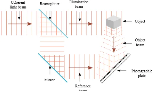
Fig. 1.1 A typical setup for holographic recording of an object by interference of two
coherent beams ... 9
Fig. 1.2 An illustration for holographic reconstruction of an object ... 11
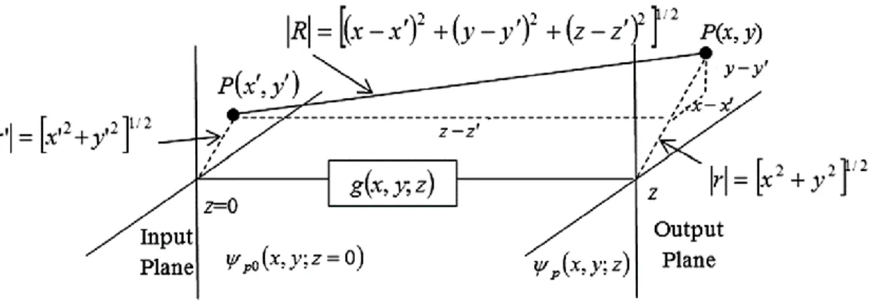
Fig. 1.3 Schematic showing the impulse response of propagation between an input and output plane. ... 14
Fig. 1.4 A flowchart of phase retrieval by iterations for generating a Fourier hologram .... 18
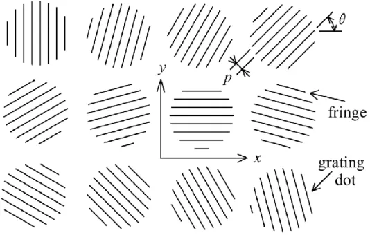
Fig. 1.5 A dot matrix hologram consisting of fine diffraction grating dots with different grating constants and orientation ... 19
Fig. 1.6 Schematic diagram of a holographic printer ... 20
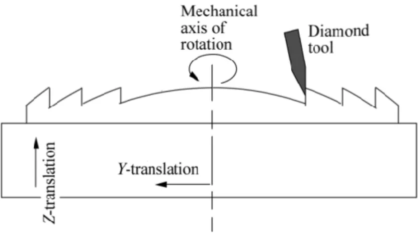
Fig. 1.7 Diamond machining of a micro-lens. ... 21
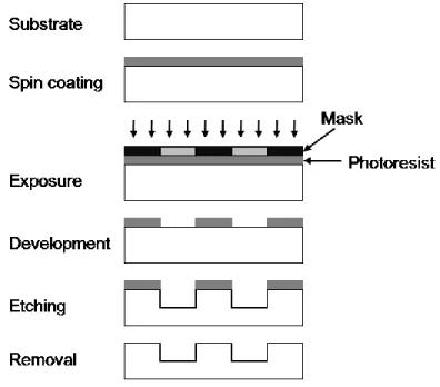
Fig. 1.8 Experimental steps of photolithography: spin coating, exposure, development, etching and removal... 22
Fig. 1.9 Experimental procedure: (I) beam focusing, (II) laser writing, (III) development, (IV) completed structure. ... 23
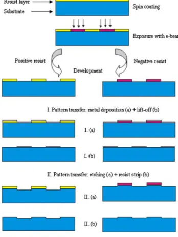
Fig. 1.10 Electron beam lithography ... 24
Fig. 2.1 Illustration of structured light. ... 26
Fig. 2.2 Schematic of wavefront reconstruction by computer-generated hologram ... 28
Fig. 2.3 (a) binary hologram designed, (b) reconstructed image by hologram shown in (a), (c) reconstructed target pattern ... 32
Fig. 2.4 (a) Binary Fresnel hologram of 512 x 512 pixels, (b) Reconstructed image from the binary hologram shown in (a) ... 33
Fig. 2.5 Reconstructed pattern from Fresnel hologram shown in Fig. 2.4 (a) at distance from the hologram (clockwise) : 30 cm, 40 cm, 50 cm and 1 km ... 33
Fig. 2.6 Optical design for a holographic projector, in which beam expansion is performed by lenses L1 and L2, and demagnification by lenses L3 and L4... 35
Fig. 2.7 Reconstructed image of 4096x4096 pixels. ... 35
XI
Fig. 2.9 (a) Projection of the final pattern with the phase mask reproduced on a fused sillica substrate, (b) Enlarged part of left-top part of projection image (a), (c) the side orders
of projection diffraction. ... 37
Fig. 3.1 Schematic diagram of polygonal aperture Ω with Q=5 straight edges. ... 44
Fig. 3.2 CGH layout (a) One period of CGH with rectangular cells divided to four triangular apertures; (b) arbitrary-shaped triangles in a cell... 46
Fig. 3.3 The selection probability and cumulative selection probability distribution for all ranked chromosome. ... 51
Fig. 3.4 The selection probability and cumulative selection probability distribution for all ranked chromosome. ... 51
Fig. 3.5 Schematic diagram of two-point crossover ... 52
Fig. 3.6 Flowchart of the hybrid GA for designing CGH of polygonal apertures... 53
Fig. 3.7 Results from the hybrid GA for assigning binary phases: (a) Normalized RMS errors as a function of generation; (b) Grayscale image of keyboard reconstructed by the CGH. ... 57
Fig. 3.8 Results by Direct Search for optimal co-vertex positions. (a) Normalized RMS errors after each round of the search, which converges to 2%; (b) Grayscale image of keyboard reconstructed from the designed CGH. ... 58
Fig. 3.9 (a) Designed binary CGH; (b) 8X enlarged part of CGH ... 59
Fig. 3.10 8X enlarged part of the image reconstructed by FFT from the designed CGH. .. 60
Fig. 4.1 CGH layout, (a) One period of CGH with rectangular cells divided to four quadrilateral apertures; (b) arbitrary-shaped quadrilateral in a cell. ... 65
Fig. 4.2 Illustration of stochastic universal sampling selection. ... 71
Fig. 4.3 Illustration of uniform crossover with a random binary mask. ... 72
Fig. 4.4 Migration topology for 4 subpopulations: one-way ring structure. ... 73
Fig. 4.5 Flowchart of the PGA with local search on each processor for designing CGH of polygonal apertures... 74
Fig. 4.6 Results from the parallel GA with local search for assigning binary phases: (a) Normalized RMS errors as a function of generation; (b) Grayscale image reconstructed by the CGH. ... 78
XII
Fig. 4.7 Results by Direct Search for optimal co-vertex positions. (a) Normalized RMS errors after each round of the search; (b) Grayscale image reconstructed from the designed CGH. ... 80 Fig. 4.8 Sixteen times enlarged part of the designed polygonal CGH ... 81 Fig. 4.9 Part of enlarged image reconstructed by FFT from the designed CGH ... 81 Fig. 4.10 Results by scheme 2: (a) image reconstructed after 10 generations of PGA with local search in step 1 (b) Normalized RMS errors after each round of direct search; (c) Grayscale image reconstructed by the CGH after step 2. ... 83 Fig. 4.11 Results by scheme 3: (a) image reconstructed after one local search in step 1 (b) Normalized RMS errors after each round of direct search; (c) Grayscale image
XIII
List of tables
Tab. 4.1 The time cost and normalized error after step 1 and then step 2 for three different schemes ... 82
XIV
Abbreviations
HGO Hologramme généré par ordinateur
CGH Computer-generated hologram
2D/3D Two-dimensional/Three-dimensional
CCD Charged coupled device
DH Digital holography
DOE Diffractive optical element
AR Augmented reality
VR Virtual reality
SLM Spatial light modulator
FoV Field of view
DoF Depth of field/focus
SBWP Space bandwidth product
DBS Direct binary search
SA Simulated annealing
GA Genetic algorithm
IFTA Iterative Fourier transform algorithm
CMOS Complementary metal oxide semiconductor
HGA Hybrid genetic algorithm
PGA Parallel genetic algorithm
CNC Computer numerical control
XV CAD Computer aided design
EBL Electron beam lithography
UV Ultraviolet
LCOS Liquid crystal on silicon
AM Amplitude modulating
PM Phase modulating
DFT Discrete Fourier transform
FFT Fast Fourier transform
MSE Mean squared error
DMD Digital micromirror device
RMS Root-mean-square
GPU Graphical processing unit
FDTD Finite-Difference Time-Domain
XVI
Dedicated to my beloved family for their love, support, encouragement and sacrifice
XVII
Acknowledge
I am deeply indebted to Professor Yunlong Sheng, my research supervisor during my PhD program at Université Laval, Quebec, for his great support and invaluable guidance of these work, and for his advice and ideas which gave me new insights in ways on how to do research.
I greatly appreciate my beloved family for providing me with courage and strength over the years. They have been always so supportive of decisions I made, even sometimes they probably don’t fully understand what I have done. Without their endless love and tireless support, it would not have been possible to finish my PhD.
I am also grateful to Y. Gravel, Dr. L. Yu and Y. Yang in Prof. Sheng’s research group, for stimulating discussions and great assistance in both work time and spare time, and to Y. Kang, Dr. H. Liang, Q. Liang, Y. Dong at Ulaval for being (or, having been) there and making (or, having made) my days in Quebec unforgettable.
I would like to extend my gratitude to Dr.Z. Jan Jakubczyk at Optiwave Systems Inc., Ottawa. He offered me a work position as research scientist, and also helped me a lot after I joined the team on Dec. 1st, 2015. Special thanks go to Kevin Chu and Dr. Steve Dods in the company for their kind help with my work when I was with Optiwave in Ottawa. A wonderful experience there!
I acknowledge my thesis evaluation panel, Prof. Simon Thibault, Prof. Pierre Marquet, Prof. Yunlong Sheng at Ulaval, and Prof. Pascal Picart at Le Mans Université in France, for accepting to evaluate my work and giving constructive feedback, and the program director Prof. Laurent Drissen for organizing and presiding over my oral defense.
I want to thank all the staff in our department (Département de physique, de génie physique et d'optique) and COPL (Centre d'optique, photonique et laser) who have ever helped me when I was on campus between 2012 and 2015.
XVIII
Foreword
Two scientific papers, coauthored by Jing Wang & Yunlong Sheng and published on peer-reviewed international journals, are presented respectively in Chapter 3 and Chapter 4 of this thesis:
1) Jing Wang, Yunlong Sheng, “Computer-Generated Very Large Space-Bandwidth Product Binary Hologram for Laser Projector,” IEEE Transactions on Industrial Informatics, Vol. 12, No. 1, pp. 179-186 (2016).
2) Jing Wang, Yunlong Sheng, “Design quadrilateral apertures in binary computer-generated holograms of large space bandwidth product,” Applied Optics, Vol. 55, Issue 27, pp. 7636-7644 (2016).
For both papers, Prof. Sheng and I discussed and conceived ideas together; I implemented the work of modeling, design and optimization under the supervisor of Prof. Sheng; I wrote the first draft of each paper and Prof. Sheng finished the final version; I am the first author and Prof. Sheng is corresponding author of both papers.
The contents in Chapter 3 are basically from the paper published on IEEE TII with additional details. Specifically, Equations (3.7) – (3.9), Figure (3.3) – (3.5) and some related words are newly added in Chapter 3.
The contents in Chapter 4 are mainly from the paper published on AO with some supplementary. In Chapter 4, Figure (4.3), (4.10), (4.11) and subsection of Figure (4.6 a) are newly presented, as well as Equation (4.12) – (4.14) and Table (4.1).
1
General introduction
Historical events of holography
The record and storage of objects, especially three-dimensional (3D) objects, had been a recurring goal of humankind after the photography was invented in 1830s. It was not really achieved until holography was discovered by Denis Gabor in 1948 [1], when he worked to address the problem introduced by the spherical aberrations of the electron lenses, which limited the resolving ability of electron microscopes [1, 2]. The word “holography” was assembled from Greek words “holos” (whole) and “graphein” (to write). Thus, holography can be defined as a technique to write or record the whole optical information from an object source for the reconstruction of the original object later. “For his invention and development of the holographic method”, Denis Gabor was awarded the Nobel Prize in Physics in 1971 [3].
The holographic process basically consists of two steps: record and reconstruction. In the first step, a holographically stored image, referred to as hologram, is produced by the interference between a wave field scattered from an object and a coherent reference wave. A hologram is usually recorded on a two-dimensional (2D) surface, for example, a photosensitive film. But it contains the whole information, i.e. both the amplitude and the phase, of the 3D object field. The information is encoded in the form of interference fringes with high spatial frequencies, which is usually invisible to human eyes. In the second step, the hologram is illuminated by original reference wave, and the diffracted light by hologram propagates to recover the object wave to form an image of object.
In Gabor’s original set-up [1], the reference wave was incident normal to the recording medium and a predominantly transparent object was in its path. The axes of both the object wave and the reference wave were parallel. This is known as on-axis hologram. This set-up is simple, but it only works when the object is small enough and sufficiently transparent so that it will not disturb the reference wave significantly. Besides, the reconstruction of this hologram gives a real image superimposed on the undifffracted part of wave and a so-called “twin image” on the same optical axis.
2
In 1956, Lohmann proposed the “single-sideband” holography [4] to handle the twin-image problem of Gabor holograms by the combination of communications theoretical and physical views of optics.
With the advent of laser by Theodore H. Maiman in 1960 [5] and the invention of off-axis hologram by Leith and Upantnieks in 1962 [6], high quality holograms could be produced and began to capture the interest of world. In their set-up, the reference waves with an oblique angle respect to normal of the recording medium did not pass through the object, which spatially separated the different diffraction orders and allows the capture of opaque objects.
The development of computer technology makes it possible to transfer the recording process and/or the reconstruction process onto the computer platform. In the middle of 1960’s Lohmann etc. realized the simulation of optical holograms by digitally generated binary transparencies, which is a big step forward in the path towards widespread applications [7-9]. This new approach was referred to computer-generated holography and the corresponding hologram was called computer-generated hologram (CGH). The CGH has the advantage that the object could be synthetic or fictitious. Its design can be optimized mathematically rather than experimentally.
Another important progress is the direct recording of holograms with Charged Coupled Devices (CCDs) by Schnars etc. in 1990s [10]. This method is known to us today as Digital holography (DH). Sometimes, computer-generated holography and digital holography are considered as the same concept, which is used to correspond to conventional optical holography.
Computer-generated holography and conventional optical
holography
The first computer-generated holograms were binary holograms invented by A. Lohmann [8, 9]). They were printed on a computer line printer, then they were optically reduced and reconstructed in optical set ups using coherent laser illumination. The computer-generated holography shares the same basic principle and concept with the conventional optical holography. However, some differences [11-15] need to be noted.
3
From what was introduced above, the record process of conventional optical holography is by optical interference, and the reconstruction of object is an optical diffraction process. The object is usually a real one; the hologram, i.e. the interference pattern is recorded by light-sensitive medium.
For the computer-generated holography, the record process is usually numerically synthesized by inverse wave propagation theory and then encoded to hologram. The reconstruction process can be either optical or numerically diffractions. Sometimes, the numerically record and numerically reconstruction is specially referred to as digital holography; only the numerically record and optical reconstruction is named as computer-generated holography. Besides, the object can be anything you may imagine; it is not necessary to be limited to the physically existing objects. It also can radiate or be illuminated by an external source. More importantly, the hologram can be fabricated or loaded to a spatial light modulator (SLM) for dynamically display.
Categories of CGHs
Over the years, computer-generated holograms (CGHs) have demonstrated to be important components for its broad range of applications [11], such as diagnostic and testing (acoustic mapping of the earth, determining particle sizes and scattering properties, analyzing vibrations, visualizing aberrations etc.), imaging and display (map displays, artist display, 3D display, image processing and deblurring, stereoscopic display etc.), structured illumination, augmented reality (AR)/virtual reality (VR), imaging system, optical storage, sensors and security etc. Many kinds of CGHs have been proposed for these different applications.
In generally, depending on the different display types in time domain, the CGHs can be categorized into two groups [12-15]:
• static CGH. For static CGH, a permanent hologram is produced. After fabricated on the substrate, the static hologram is also called as diffractive optical elements (DOEs). • dynamic CGH. For dynamic CGH, it is usually loaded onto spatial light modulators
4
Depending on the material with which the CGH is to be fabricated, there are typically three types [12, 13]:
• Phase-only CGH, where the material modulates only the phase of an incoming wavefront, and the transmittance amplitude is unity;
• Amplitude-only CGH, where the material modulates only the amplitude of an incoming wavefront, and the transmittance phase is constant;
• Complex-amplitude CGH, where such a material modulates both the amplitude and phase of the incoming wavefront.
The CGHs can be grouped as the way they utilize resources [14]:
• Point-oriented CGHs, in which each pixel is uniform; there is no sub-element. Each pixel will be assigned a value of the transmittance which corresponds to pixel value in the actual hologram.
• Cell-oriented CGHs, on the other hand, manipulate the sub-structure in each hologram cell so that each cell consisting of pixels controls amplitude and phase in some ways.
Depending on where the image reconstructed is observed, there are several types of CGH [14, 15], among which the most important two are:
• Fourier CGH: the image is reconstructed at back focal-plane of the second lens of the 4-F imaging system.
• Fresnel CGH: the image is reconstructed in at a distance far enough from the CGH so that the parabolic (or, Fresnel) approximation can be used.
Current research of CGHs
Since one of the main objectives of holography is to record and display of 2D/3D object, current research of CGH usually refers to the following 4 topics: object data acquisition, object wave representation, hologram encoding and image reconstruction.
The first research topic is about how to acquire the geometry of the object, especially 3D object. One of approaches is to acquire 2D projections of the object from different perspective viewpoints using 2D camera array [16] or by moving one single camera [17]. Another one is
5
to adopt 2D-plus-depth cameras [18] to get 2D views and depth information. The acquired object data can then be directly used for CGH.
The second one is to represent the object wave. The point-source approach [15] is one of the most commonly used to compute the object wave, which is the sum of spherical waves by each object point. Another technique for object wave is wave-field approach, which can be based on a layered model [19, 20] or a polygonal model [21] of 3D object. In the former model, the 3D object is sliced into a set of layers, which operates as a surface source of light. While in the latter one, 3D scenes are described as a set of oriented polygons acting as a surface source of light. The associated occlusion processing [22, 23], surface shading [24] and computation time reduction [25, 26] are widely studied as well.
The third topic is how to encode hologram. The object wave computed is usually a complex-valued field. However, to be displayed on a screen or printed onto a transparency, the real positive values of hologram must be quantized to some levels. The previously mentioned phase-only hologram [27], amplitude-only hologram [28] and complex-amplitude hologram [29] are three encoding types. Another problem related is to use data compression techniques [30, 31] to reduce the amount of holographic information to be stored and transmitted since it could be very huge.
The last one is about image reconstruction. Current SLMs have limited resolutions and pixel pitches much larger than wavelength used, which prevent SLMs from providing a large diffractive angle [32, 33].
Design procedures of CGHs
As mentioned earlier, CGHs are numerically synthesized by inverse wave propagation theory. The design procedures of CGHs can basically be divided into three parts [12, 13]:
First, analysis the design problem and understand the physics behind it. In this part, the main task involves calculation of the fields that should be generated on the hologram plane produced by the object, i.e. the inverse wave propagation of the desired light pattern. One usually need to know if the scalar diffraction is accurate enough to solve the problem and may further decide the possible Fresnel or Fourier transform on the object fields. If scalar diffraction theory is not valid for some cases, full vector theory needs to be employed.
6
The second part of the design is the choice of encoding way into the hologram plane and then define an appropriate optimization algorithm. The fields calculated on the hologram plane in the last step are usually complex fields. One should choose the proper modulation method, which will be used to encode into hologram to form a desired transparency. The adoption of optimization algorithm needs to comprehensively consider the modulation way, the type of CGH, optimization speed and performance, computation resources etc. The main goal of the optimization is to obtain a hologram that will generate a reconstruction pattern as close as possible to the desired pattern.
The third part is to execute the design and fabricate the hologram. The fabrications of the hologram usually bring some extra errors due to the machine tolerance. In fact, the resolution of the machine plays on important role on determining the encoding and the optimization algorithm, which need to be considered in advance.
The motivation
Although great development and success has been made since CGH’s invention, with the advancement of modern fabrication technology and emergence of application in new fields, some challenges still exist when design the CGHs. This thesis aims to model, design, and optimize CGHs regarding the two specific issues below.
One of the issues is how to design CGH for the practical projection system. Besides consideration of reconstruction error, diffraction efficiency of CGH and stray light from unwanted high diffraction orders, the specifications of practical projection system usually force designers to look upon more factors, typically including working distance, working wavelength (range), diffraction angles - field of view (FoV), and depth of field/focus (DoF) etc. Meanwhile, the abilities of facility equipment for fabricating CGH should also be considered before the design, such as the resolution can be achieved, the maximum capacity of data can be read, the speed of wring and sometimes even the financial cost etc. All these factors need to be proper treated and weighted, which greatly increase the complexity of designing CGH in a practical projection system.
Another issue concerned is that how to design and optimize CGH of large space bandwidth product (SBWP). With the advancement of industrial fabrication technology, the minimum
7
feature size can achieve is far less than the order of visible wavelength. For example, with the e-beam lithography, the pixel size can reach to 50 nm, or even 5 nm. With a pixel size of 50 nm, a CGH with one-inch square size will have 258 gigapixels, which provides a huge number of degree of freedom. The conventional optimization algorithm for CGH can not well handle. The main challenge is that how to manage such a huge number of degree of freedom to achieve the best performance in the scope of scale diffraction theory.
Organization of thesis
With respect to the content of the thesis, it will be organized as follows.
A general introduction on the holography and CGH is given at the beginning, including a short review of historical events, basic idea of holography, a list of categories of CGH and current research as well. This part also briefly introduces design procedures of CGH and the issues that this thesis attempts to answer, i.e. the design and optimization of CGH applied to a practical projection imaging system, and CGH with huge number of degree of freedom. The organization of thesis is presented in the end of the introduction.
In Chapter 1, the fundamental of holography and the underlying theory used - scalar diffraction theory are detailed. Besides, several classic algorithms of designing CGHs - DBS, SA, GA and IFTA, are introduced, together with two industrial technologies - dot matrix hologram and holographic prints. Also, four fabrication technologies for CGH are briefly presented.
In Chapter 2, we talked about how to design a CGH for a structured-light projector with certain specifications. This projector system has a working distance of 40 cm, and a 10 cm depth of field (DoF). The pattern angle is around 53 degree. The wavelength of used optical source is 632 nm. The direct binary search (DBS) algorithm is demonstrated first by designing a Fourier hologram with binary phases and then further applied to synthesizing Fresnel hologram with binary phases, which meet the requirements of the projector. The consideration of optical architecture design in the projection system was discussed. The fabrication of hologram and experimental results were shown as well.
8
In Chapter 3, we proposed a new approach for designing binary CGH with arbitrary-shaped polygonal apertures. With this method, the high number of degrees of freedom available in CGH of large space bandwidth product (SBWP) can be fully explored. The Abbe transform was introduced and used to compute the diffraction pattern. A two-step optimization algorithm including hybrid GA for assigning binary phase and direct search for floating co-vertices of the elementary triangular apertures was developed to reconstruct image with high performance.
In Chapter 4, we further investigate to directly design quadrilateral aperture in binary CGHs of large SBWP, which exploit higher number of degree of freedom compared with that in CGHs based on triangular aperture layout. Coarse grained parallel GA with local search is used in the first step to assign phases and direct search is adopted in the second step to optimize the positions of vertices. Three schemes of this two-step algorithm were discussed to give us a flexible way to balance between the time cost and optimal results.
9
Chapter 1 Theory, algorithms and fabrications of
holograms
1.1 Fundamental of holography
The fundamental problem addressed by holography is recording and later reconstructing, both the amplitude and the phase of an optical wave from a coherently illuminated object. A typical setup is shown in Fig. 1.1. Light with sufficient coherence is split into two waves of reduced amplitude by a beam splitter. The first wave illuminates the objects, is scattered at the object surface towards the recording medium. The second wave, i.e. the reference wave, directly illuminates the light sensitive medium. The waves interfere with each other to produce a characteristic interference pattern. In classical photographic holography the interference pattern is recorded on a photosensitive material such as silver halide films or plates and rendered permanent by wet chemical development of film. In digital holography the interference pattern is recorded directly onto an electronic sensor array such as a Charged Coupled Devide (CCD) or Complementary Metal Oxide Semiconductor (CMOS). The recorded interference pattern is the hologram [13-15].
10
The holographic process is described mathematically by the formalism of interference of light. If the complex amplitude of the object wave is described by
( , ) ( , )exp ( , )
O O O
E x y =A x y i x y
(1.1 )
with real amplitude AO and phase O. And the complex amplitude of the reference wave with
real amplitude AR and phase R is represented by
( , ) ( , )exp ( , )
R R R
E x y =A x y i x y
(1.2 )
Both waves interfere at the surface of the recording medium and the resultant intensity is calculated by ( ) ( ) ( ) ( ) ( ) ( ) ( ) ( ) ( ) ( ) ( ) ( ) ( ) ( ) ( ) ( ) ( ) ( ) ( ) 2 * * * * 2 2 , , , , , , , , , , , , , , , exp , , exp O R O O O R R O R R O R O R O R O R O R I x y E x y E x y E x y E x y E x y E x y E x y E x y E x y E x y A x y A x y A x y A x y i A x y A x y i = + = + + + = + + − + − − (1.3 )
while the first two terms of this expression depend only on the intensities of the individual waves, the third and fourth depends on their relative phases. Thus, information about both the amplitude and phase of EO has been recorded.
The material used to record the interference pattern will be assumed to provide a linear mapping of intensity. For simplicity, suppose t x y( , )= 1 I x y( , ).
Once the amplitude and phase information about the object wave have been recorded, it remains to reconstruct that wave. If the coherent reconstruction wave EC is represented by
( , ) ( , )exp ( , )
C C C
E x y =A x y i x y (1.4 )
Then the light diffracted by the hologram is evidently
( ) ( ) ( ) ( ) ( ) ( ) ( ) ( ) ( ) ( ) ( ) ( ) ( ) ( ) ( ) 2 2 , , , , , , exp , , , , exp , , , exp D C O R C C O R C O C R O R C R C O E x y E x y t x y A x y A x y A x y i x y A x y A x y A x y i A x y A x y A x y i = = + + + − + + − (1.5 )
11
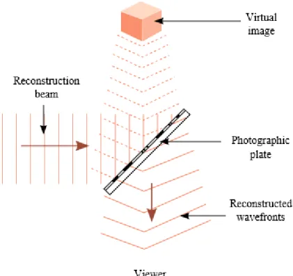
Fig. 1.2 An illustration for holographic reconstruction of an object
Note that if EC is simply an exact duplication of the original reference wave ER,
( , ) ( , ) ( , )exp ( , )
C R R R
E x y =E x y =A x y i x y (1.6 )
Then, Eq. (1.5) can be rewriten as
( ) 2( ) 2( ) ( ) 2( ) ( ) 2( ) ( ) (* )
, , , , , , , exp 2 ,
D O R R R O R R O
E x y =A x y +A x y E x y +A x y E x y +A x y i E x y (1.7 )
The first term on the right side of Eq. (1.7) is the reference wave multiplied by a constant factor. It represents the non-diffracted wave passing through the hologram (zero diffraction order). The second term is the reconstructed object wave and forms the virtual image, as shown in Fig. 1.2. The real factor 2
R
A only influences the brightness of the image. The third
term generated a distorted real image of the object (with 3D shapes). The reason for the distortion of the real image is the spatially varying complex factor exp 2(i R) , which
modulates the image forming conjugate object wave *
O E .
12
In a similar fashion, if EC is chosen as the conjugate of the original reference wave ER,
( ) *( ) ( ) ( ) , , , exp , C R R R E x y =E x y =A x y −i x y (1.8 ) Then we have ( ) 2( ) 2( ) *( ) 2( ) ( ) ( ) 2( ) (* ) , , , , , exp 2 , , , D O R R R R O R O E x y =A x y +A x y E x y +A x y −i E x y +A x y E x y (1.9 )
The third term is proportional to the conjugate of the original object wave *
O
E , which
represents an undistorted real image.
1.2 Scalar diffraction theory
1.2.1 Wave equation
According to the differential form of Maxwell’s equations for source-free medium [34, 35],
, , 0, 0. B E t D H t D B = − = = = (1.10 )
Taking the curl of Eq. (1.10.1) produces
(
)
, B H D E H t t t t t = − = − = − = − (1.11 )With D=ɛE, after Substituting Eq. (1.10.2) to Eq. (1.11), we get
2 2 E E t = − (1.12 )
with the property
(
)
2E E E = − , , we have 2 2 2 E E t = (1.13 )
13
where =1 is the velocity of the wave in the medium.
Suppose represent a component E , x Ey or E of the electric field z E .
2 2 2 2 2 2 2 2 2 1 x y z t + + = (1.14 )
The solution will be in form of
(
x y z t, , ,)
p(
x y z, ,)
exp(
i 0t)
= (1.15 )
Substituting Eq. (1.15) into Eq. (1.14) produces the well-known Helmholtz equation [35]:
2 2 2 2 0 2 2 2 0 p p p p k x y z + + + = (1.16 )
where k0 is the propagation vector, and 2 2 2 0
0 0 0x 0y 0z
k =k = k +k +k = , is called wave number.
1.2.2 Spatial frequency transfer function
Denote p to be the Fourier transform of with respect to the transverse spatial coordinates
(x, y), as shown in Fig. 1.3. With the Fourier transform we have
2 2 2 2 0 2 2 2 0 0 1 0 p x y p d k k k dz k k + − − = (1.17 )
, which is a second-order, homogeneous, linear ordinary differential equation with constant coefficients. The solution can be written as
(
)
(
)
2 2 0 2 2 0 0 , , , , 0 exp 1 x y p x y p x y k k k k z k k ik z k k = − − − (1.18 )The spatial frequency transfer function [36] along z direction can be defined as
(
)
(
(
)
)
2 2 0 2 2 0 0 , , , , exp 1 , , 0 p x y x y x y p x y k k z k k G k k z ik z k k k k = = − − − (1.19 )14
1.2.3 Fresnel diffraction and Fraunhofer diffraction
Fig. 1.3 Schematic showing the impulse response of propagation between an input and output plane.
When propagating waves make small angles, i.e. under the so-called paraxial approximation,
we have 2 2 2 0 x y k +k k and then
(
)
(
)
(
)
2 2 0 2 2 0 0 2 2 2 2 0 2 0 0 0 , , exp 1exp 1 exp exp
2 2 y x x y x y x y k k G k k z ik z k k k k k k ik z ik z iz k k = − − − + + − − = − (1.20 )
The impulse response of propagation g x y z
(
, ,)
can be obtained by performing the inverse Fourier transform of G,(
)
(
)
(
)
1 2 2 0 0 0 , , , , exp exp 2 2 x y g x y z F G k k z ik x y ik z ik z z − = + = − − (1.21 )Perform inverse Fourier transform to revert to space domain,
(
)
(
)
(
) (
)
(
) (
)
1 1 , , , , , , 0 , , , , 0 * , , p p x y p x y x y p x y z F k k z F k k G k k z x y g x y z − − = = = (1.22 ) then,(
)
(
)
0(
)
0(
) (
2)
2 0 , , exp , , 0 exp 2 2 p p ik ik x y z ik z x y x x y y dx dy z z = − − − + −
(1.23 )15
This is called the Fresnel diffraction formula [36]. The range of applicability of the Fresnel diffraction formula spans the near field of the object to the far field.
If only the far-field diffraction pattern is of interest, another approximation can be made to yield the Fraunhofer diffraction formula [36].
(
)
(
)
(
)
(
)
(
)
(
)
(
)
(
)
(
)
(
)
(
)
2 2 0 0 0 2 2 0 2 2 0 0 0 2 2 0 0 , , exp exp 2 2 , , 0 exp 2 2 2 exp exp 2 2 , , 0 exp exp 2 p p p ik ik x y z ik z x y z z ik x y x y xx yy dx dy z ik ik ik z x y z z ik ik x y x y xx yy dx dy z z = − − + − + + + = − − + − + +
(1.24 )For Fraunhofer approximation, the term
(
2 2)
x y
+ is like the maximum area of the source
and if this area divided by the wavelength is much less than the distance z under consideration,
the term 0
(
2 2)
exp 2 ik x y z − + inside the integrand can be considered as unity, so
(
)
(
)
(
)
(
)
(
)
(
)
(
)
(
)
2 2 0 0 0 0 2 2 0 0 0, , exp exp , , 0 exp
2 2 exp exp , , 0 2 2 p p p ik ik ik x y z ik z x y x y xx yy dx dy z z z ik ik jk z x y F x y dxdy z z = − − + + = − − +
(1.25 )Fresnel diffraction formula and Fraunhofer diffraction formula can also be obtained based on Rayleigh-Sommerfeld diffraction model of the well-known Huygens-Fresnel principle. From the standpoint of object wavefront reconstruction, Fresnel holograms differ from Fourier holograms in that they have focusing properties and are capable of reproducing the finite distance from the observation surface to the object.
1.3 Conventional algorithms for CGHs design
According to the optical propagation model from the CGH plane to reconstruction plane, the algorithms for CGHs design can usually be divided into two groups: unidirectional algorithm
16
and bidirectional algorithm. For unidirectional algorithm, the optical propagation will only be calculated in the forward direction. Typical examples of unidirectional algorithms are Direct Binary Search (DBS) [37, 38], Simulated Annealing (SA) [14, 39, 40] and Genetic algorithm (GA) [41, 42]. While for the bidirectional algorithm, the inverse propagation from the image plane to CGH plane will also be calculated. the classic Iterative Fourier Transform Algorithm (IFTA) [43] and IFTA-based phase retrieval algorithm [44, 45] belong to this group.
1.3.1 Direct Binary Search
The basic idea of DBS is to begin with a random CGH with binary phases and flip the value in a pixel-by-pixel order till all the pixels are scanned. After each change of the value encoded into a pixel, the impact of such change on the image reconstructed is evaluated. If the image is improved, then the flipping is accepted, otherwise rejected. Such process is repeated until no more single pixel changes to produce a better image within given iteration number.
This can ensure the DBS results in a solution with a simple implementation way, however, at the expense of a huge number of flip trials. The main drawback of DBS is that it often converges to a local optimum instead of a globe one.
1.3.2 Simulated Annealing
Simulated Annealing is a probabilistic technique for approximating the global optimum of a given function in a large search space. The name and inspiration come from annealing in metallurgy – a technique involving heating and controlled cooling of a materials to increase the size of its crystals and reduce their defects. One of implementation of SA is quite similar with DBS. As before, changes that lead to a better image quality will be accepted unconditionally. However, it will also probabilistically accept the value inversions of hologram pixels that increase the error of image reconstruction. The probability of accepting these inversions is relatively large, and as the iteration goes, the probability decreases. In this way, SA can avoid stopping when a local optimum is reached, as that in DBS. It will usually give a better result than DBS, but with a slower convergence.
17
1.3.3 Genetic algorithm
Genetic algorithm is a method based on natural selection, the process that drives biological evolution. It repeatedly modifies a population of individual solutions randomly generated by selecting individuals from the current population to be parents and uses them to produce the children for the next generation via crossover. Mutation is then applied some random change to maintain the genetic diversity of the genes in the children. Over successive generations, the population evolves toward an optimal solution. The selection, crossover and mutation are three main operations in classic GA. For each operation, there are many different ways to implement. Sometimes, elitism strategy will also be introduced, which means the best individual in a population is transmitted to the next generation without crossover and mutation. GA can be also used together with other conventional algorithms, such as direct search, gradient search etc., which was named as hybrid genetic algorithm (HGA). In some cases, HGA can converge much faster than classic GA.
Compared with DBS and SA, which are essentially serial optimization algorithms, parallel genetic algorithm (PGA) can be easily developed to take advantage of modern computer technology.
1.3.4 Iterative Fourier Transform Algorithm
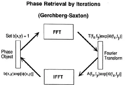
The IFTA was first proposed by Hirsch et al. Gerchberg and Saxton independently dealt with the phase-retrieval problem using a similar algorithm, and thus the IFTA is also called the Gerchberg-Saxton (G-S) algorithm. Fig. 1.4 shows a general flowchart of the IFTA for generating a Fourier hologram. The algorithm consists of the following four simple steps: (1) Fourier transform an estimate of the object; (2) replace the modulus of the resulting computed Fourier transform with the measured Fourier modulus to form an estimate of the Fourier transform; (3) inverse Fourier transform the estimate of the Fourier transform; and (4) replace the modulus of the resulting computed image with the measured object modulus to form a new estimate of the object. The generalized Gerchberg-Saxton algorithm can be used for any problem in which partial constraints (in the form of measured data or information known a priori) are known in each of two domains, usually the object (or image) and Fourier domains.
18
One simply transforms back and forth between the two domains, satisfying the constraints in one before returning to the other.
Fig. 1.4 A flowchart of phase retrieval by iterations for generating a Fourier hologram
1.4 Industrial schemes for CGH design
For many industrial applications, holograms have relatively large sizes, i.e. space bandwidth product (SBWP). Meanwhile, the low fabrication cost of hologram is very important for mass manufacture. Therefore, those conventional optimization algorithms listed above are usually inappropriate for design of industrial holograms. Herein, as two widely used industrial schemes, the dot matrix technology (dot matrix hologram) [46-53] and holographic printer [54-64] are introduced.
1.4.1 Dot matrix hologram
Dot matrix hologram [46-53], as shown in Fig. 1.5, is a type of hologram that is composed of thousands of fine diffraction grating dots with different grating constants and orientation, which can be controlled by computer according to the pattern design. These diffraction grating dots can be exposed onto a photoresist plate forming a relief hologram that is used for mass production with embossing technique. Controlling the angle, exposure, size, shape,
19
and spacing of every grating in the hologram, allows the end-user a wide range of visual effects. When illuminated with white light the gratings split the light into a spectrum of colors and redirect the light at various angles to form a kinetic hologram image. Because of large visual angle, high diffraction efficiency and kinetic visual effect of dot matrix holograms, they are widely used in security printing and anti-counterfeiting.
Fig. 1.5 A dot matrix hologram consisting of fine diffraction grating dots with different grating constants and orientation
Electron beam writers, pattern copiers, and two-beam writers can be used to create dot-matrix holograms. For brightness of dot-matrix holograms, holograms created by e-beam writers are brightest and those created by pattern copiers are darkest. For mastering speeds, pattern copiers are fastest and beam writers are slowest. For machine prices and running costs, e-beam writers are very expensive, but two-e-beam writers and pattern copiers are cheap. Because the performance of two-beam writers is always at the balance position for all the above-mentioned features, two-beam writers are more popular than e-beam writers and pattern copiers.
1.4.2 Holographic printer
Holographic printing technology has been largely reported recently [54-64]. A common feature of all holographic printers is division of the printed hologram into a 2D array of
20
holographic elements (hogels). Information to be recorded in a hogel is displayed on a SLM. Recording of the whole hologram is done by successive exposure of all hogels using a motorized X-Y translation stage, as shown in Fig. 1.6.
Holographic printers can be basically classified into two categories. One is “holographic stereogram printer”. It can be only used for the holographic stereograms, which are synthesized from sequences of closely spaced two-dimensional (2D) perspective views and not faithfully reconstructs wavefront of the recorded object. These series of 2D perspective images are stored in hogels. With an appropriate illumination, each hogel in the holographic stereogram diffracts a fraction of perspective images within a certain viewing angle. The diffracted lights are fractions of the perspective image recorded on the hogels in the holographic stereogram. On the observing plane, relatively large numbers of viewing points are formed by the merged lights diffracted from the hogels. An observer can see a 3D image from these perspective views at the corresponding viewing point. When the observer’s left and right eyes are located at different viewing points, the observer sees stereoscopic images and perceives 3D images.
21
The other one is “holographic printer for CGH”, which can print the hologram that reconstructs wavefront from any kind of CGH and also the computer-generated holographic stereogram. The holographic fringe printer transfers the input CGH into a holographic emulsion forming a thin hologram and thus this printing method lacks color selectivity. The holographic volume printer decodes the 3D object wavefront from the CGH and records it as an analogue volume hologram. Since its wavelength selectivity, it is suitable for while-light reconstruction hologram, particularly for a full-color hologram.
1.5 Fabrication technologies of holograms
1.5.1 Diamond machining
One of the first techniques for fabrication of holograms is diamond machining [65-67], which can generate diffractive microstructures directly through mechanical removal of optical material. It is a process of mechanical machining of precision elements using lathes or derivative machine tools (e.g., turn-mills, rotary transfers) equipped with natural or synthetic diamond-tipped tool bits, as shown in Fig. 1.7.
Diamond machining is a multi-stage process. Initial stages of machining are carried out using a series of computer numerical control (CNC) lathes of increasing accuracy. A diamond-tipped lathe tool is used in the final stages of the manufacturing process to achieve sub-nanometer level surface finishes and sub-micrometer form accuracies. The surface finish quality is measured as the peak-to-valley distance of the grooves left by the lathe.
22
1.5.2 Photolithography
Photolithography, also termed optical lithography or UV lithography, is a process used in microfabrication to pattern parts of a thin film or the bulk of a substrate [68, 69]. It uses light to transfer a geometric pattern from a photomask to a light-sensitive chemical "photoresist" on the substrate. A series of chemical treatments then either engraves the exposure pattern into or enables deposition of a new material in the desired pattern upon the material underneath the photo resist. The process is illustrated in Fig. 1.8.
Firstly, a photoresist layer is deposited on a substrate by spin coating. The thickness of the photoresist layer depends on the viscosity and the spin coating speed. Secondly, a binary mask of alternating transparent and opaque areas is fabricated using some type of pattern generator. The mask is laid on a substrate coated with a thin layer of photoresist, which is exposed to ultraviolet light through the mask. After the resist is developed, a pattern is created in the photoresist layer. The substrate is then etched until the required depth is reached. The photoresist pattern is then removed, resulting in a binary element.
Fig. 1.8 Experimental steps of photolithography: spin coating, exposure, development, etching and removal.
23
Direct laser writing (DLW), also known as Multiphoton lithography, is a three-dimensional (3D) printing technology which allows the construction of readily assembled structures with sub-100 nm resolution [70-72]. Similar to standard photolithography techniques, structuring is accomplished by illuminating photoresists via light of a well-defined wavelength. The fundamental difference, however, is that this method relies on nonlinear photon absorption by photopolymers. The beam of an ultra-fast laser is tightly focused inside the volume of a transparent material, causing it to absorb two or more photons and polymerize locally. Moving the beam according to a path representing a Computer Aided Design (CAD) model, one can fabricate a realistic micromodel of this design.
The experimental procedure for fabricating a 3D structure by DLW is shown in Fig. 1.9. (I) The laser beam is tightly focused into the volume of the material. (II) Either the focused beam or the sample move following a computer-generated pattern. (III) After the laser writing of the structure, the sample is immersed into an appropriate developer. (IV) The freestanding structure is revealed.
Fig. 1.9 Experimental procedure: (I) beam focusing, (II) laser writing, (III) development, (IV) completed structure.
1.5.4 Electron beam lithography
Electron beam lithography (EBL) is a powerful technique [73, 74] for creating nanostructures that are too small to fabricate with conventional photolithography. State of the art EBL
24
systems can achieve resolutions of a few nanometres. The technique works by moving a highly focussed electron beam over a sample to write out a pattern designed with suitable CAD tools.
The pattern is recorded in an electron sensitive film (or resist) deposited on the sample before exposure by spin coating. The electron beam induces a change in the molecular structure and solubility of the resist film. Following exposure to the electron beam, the resist is developed in a suitable solvent to selectively dissolve either the exposed or unexposed areas of the resist. After exposing and developing, the resist layer on top of the sample can be used as a mask or template for transferring the pattern into a more useful medium, as shown in Fig. 1.10.
The advantage of e-beam lithography stems from the shorter wavelength of accelerated electrons compared to the wavelength of ultraviolet (UV) light used in photolithography, while the main drawbacks are the high cost and the slow exposure process of EBL system, resulting in a long writing time (several hours) for relatively small areas (usually a few mm2).
25
Chapter 2 Design of holograms by direct binary search
for structured-light projection system
2.1 Introduction
Three-dimensional (3D) surface imaging [75], as one of the fundamental topics in computer vision, have made tremendous progresses in research, development and commercialization in the recent decades because of its great application demands in a variety of market segments. Some typical examples include industrial inspection, cultural heritage, dental health care or object recognition. One of the most widely used techniques is based on the projection of structured light [76, 77], which is active illumination of the scene with specially designed 2D spatially varying intensity pattern.
As illustrated in Fig. 2.1, a spatially varying 2D structured illumination is generated by a projector. The intensity of each pixel on the structured-light pattern is represented by the digital signal. An imaging sensor, for instance, a camera is used to acquire a 2D image of the scene under the structured-light illumination. If the scene is a planar surface without any 2D surface variation, the pattern shown in the acquired image is similar to that of the projected structured-light pattern. However, when the surface in the scene is nonplanar, the geometric shape of the surface distorts the projected structured-light pattern, as seen from the camera. The principle of structured light 3D surface imaging techniques is to extract the 3D surface shape based on the information from the distortion of the projected structured pattern. As shown in Fig. 2.1, the geometric relationship between an imaging sensor, a structured-light projector and an object surface point can be expressed by the triangulation principle [75]. There are many kinds of structured-light patterns [75, 78] for the surface imaging technique, among which, the binary pattern [79-81] is one of the reliable and simple structured patterns.
In a variety of projection imaging system [82-84], computer-generated holograms (CGHs) are widely used. Such devices can be realized as static structures etched, which are sometimes called diffractive optical elements (DOEs), or displayed on dynamically micro-display devices such as liquid crystal on silicon (LCOS). In both cases, the CGHs can perform the
26
entire functionality associated with optical assembly containing many components like lens, in the imaging system, leading to more compact, convenient, reliable and low-cost scheme. The diffraction property of CGH potentially allows for projection angles much larger than the conventional projection system which are limited by the necessity for a relatively large projection lens. Although being able to enlarge image, the lens assembly may bring severe aberrations, which can only be handled by the corporation of highly complex and expensive lens system. The conventional lens assembly is not a good choice for projection, particularly in the miniaturized projector [84].
Fig. 2.1 Illustration of structured light.
Moreover, compared with the amplitude modulating (AM) technique used in conventional projector, which selectively block incident light to form the desired image, a holographic projector employing a phase modulating (PM) CGH has a transmission of unity, in which the improvement of diffraction efficiency can be expected. A phase-only holographic projector is also able to exert control over the imaging system with a wide projection angle, so that the project system can be built without residual optical aberrations. Besides, extended depth-of-field in holographic projectors is reported as an advantage as well compared with that in conventional projectors [86]. Basically, the pixel size of CGH employed in a holographic projection system should be as small as possible, so that subsequent lens power in the system to achieve the desired projection angle is minimized [84]. Nevertheless, due to the resolution of lithography usually used, design of CGH, fabrication of DOE and construction of a practical projection system with certain specifications need to be comprehensively considered.