HAL Id: hal-00595998
https://hal.archives-ouvertes.fr/hal-00595998
Submitted on 26 May 2011
HAL is a multi-disciplinary open access
archive for the deposit and dissemination of
sci-entific research documents, whether they are
pub-lished or not. The documents may come from
teaching and research institutions in France or
abroad, or from public or private research centers.
L’archive ouverte pluridisciplinaire HAL, est
destinée au dépôt et à la diffusion de documents
scientifiques de niveau recherche, publiés ou non,
émanant des établissements d’enseignement et de
recherche français ou étrangers, des laboratoires
publics ou privés.
A Reconfigurable Multi-core cryptoprocessor for
Multi-channel Communication Systems
Michael Grand, Lilian Bossuet, Guy Gogniat, Bertrand Le Gal, Jean-Philippe
Delahaye, Dominique Dallet
To cite this version:
Michael Grand, Lilian Bossuet, Guy Gogniat, Bertrand Le Gal, Jean-Philippe Delahaye, et al.. A
Reconfigurable Multi-core cryptoprocessor for Multi-channel Communication Systems. IPDPS - 25th
IEEE International Parallel & Distributed Processing Symposium, May 2011, Anchorage, United
States. pp.199-206. �hal-00595998�
A Reconfigurable Multi-core Cryptoprocessor for
Multi-channel Communication Systems
Michael Grand
1, Lilian Bossuet
2, Guy Gogniat
3, Bertrand Le Gal
1, Jean-Philippe Delahaye
4and Dominique Dallet
1 1IMS Laboratory, University of Bordeaux, [email protected]2Hubert Curien Laboratory, University of Lyon, [email protected] 3Lab-STICC Laboratory, University of Bretagne Sud, [email protected]
4CELAR, DGA, [email protected]
Abstract—This paper presents a reconfigurable Multi-Core Crypto-Processor (MCCP) especially designed to secure
multi-channel and multi-standard communication systems. Such com-ponent meets many constraints like high throughput and flexibil-ity. In contrast, a classical mono-core approach either provides limited throughput or does not allow simple management of multi-channel streams. Nevertheless, parallelism is not sufficient for a multi-standard radio. It is therefore essential to increase MCCP flexibility. To achieve these results, our work takes advantage of the Xilinx FPGA hardware reconfiguration. The proposed MCCP can reach a maximum throughput of 1.7 Gbps at 190 MHz with several AES cipher modes. It uses about 4000 slices on a Virtex 4 FPGA.
Index Terms—Software Defined Radio, Crypto-processor,
Multi-core
I. INTRODUCTION
Multiplicity of wireless communication standards (UMTS, WiFi, WiMax) needs highly flexible and interoperable com-munication systems. Software based solutions such as
Soft-ware Defined Radio (SDR) are used to meet the flexibility
constraint. Independently, most of radios have to propose cryptographic services such as confidentiality, integrity and authentication (secure-radio). Therefore, integration of cryp-tographic services into SDR devices is essential.
By using symmetric cipher and hash function, it is possible to propose such services. However, the use of cryptographic functions in secure systems tends to limit their overall through-put. The best performance is achieved by using dedicated hardware cryptographic accelerator to provide cryptographic services [1], [2]. These cores can reach throughput of tens of gigabits per second using loop unrolling, pipelining and channel interleaving mechanisms. Although, these throughput efficient cores are useful for mono-standard communication systems, they do not provide the level of flexibility needed by multi-standard systems (due to their dedicated architec-ture). On the contrary, more flexible crypto-processors do not always provide a sufficient throughput for multi-channel applications [19].
To overcome these issues, this paper presents a reconfig-urable Multi-Core Crypto-Processor (MCCP) especially de-signed to provide both flexibility and high throughput in order to secure multi-standard and multi-channel communication streams. To achieve these results, the MCCP architecture is
a trade-off between a throughput efficient design and a multi-mode design. Moreover, its modular and reconfigurable design (by using FPGA hardware reconfiguration) allows to use any 128-bit block cipher algorithm (e.g. AES, Twofish, Serpent, ...). In this paper, the AES algorithm is used as an illustration. This architecture, which provides a maximum throughput of 1.7 Gbps at 190 MHz on a Virtex4 FPGA, supports most of the block cipher modes of operation such as CTR, CCM, GCCM and CBC-MAC.
The paper is organized as follows: Section 2 introduces multi-channel and multi-standard issues to choose suitable computing architecture. Section 3 presents the top level ar-chitecture of the proposed MCCP. Sections 4 and 5 detail the lower layers of the MCCP architecture (i.e. Cryptographic
Core and Cryptographic Unit). MCCP operation is explained
in section 6 using some didactic examples, according to these examples section 7 provides experimental results. Section 8 discusses the implementation of MCCP operating system. Finally, section 9 concludes this paper.
II. CRYPTOGRAPHICARCHITECTUREDESIGN FOR
INTENSIVECOMMUNICATIONSYSTEMS A. Design Constraints
The design of a multi-standard and multi-channel secure SDR faces two main constraints:
• A multi-standard secure SDR has to provide several cryptographic algorithms.
• A multi-channel secure SDR device handles two or more communication channels at the same time.
In consequence, designers have to choose a trade-off be-tween flexibility, throughput performance and area cost. In this paper, a loosely coupled multi-core crypto-processor is presented as an alternative to mono-core crypto-processors and tightly coupled multi-core crypto-processors. This architecture is designed to improve the flexibility/performance trade-off of communication crypto-processors. The next part briefly describes previously published works dealing with hardware cryptographic architectures.
B. Previous Works
The best performance (in terms of throughput) are pro-vided by pipelined cryptographic accelerators. In such cores,
encryption algorithm is fully unrolled to produce an effi-cient pipelined design. For example, GCM (Galois Counter
Mode [7]) is especially designed to take profit of pipelined
cores. There are several works dealing with hardware im-plementations of AES-GCM core. [1], [11], [12] are few examples of such implementations which allow throughput of tens of gigabits per second. But, this kind of architecture has several drawbacks.
Firstly, algorithm unrolling leads to high hardware re-source consumption. Secondly, data dependencies in some block cipher modes (e.g. CCM for Counter with CBC-MAC
Mode [6]) make unrolled implementations useless. Finally,
complex designs are needed when multiplexed channels use different standards. In consequence, pipelined cores are better suited for mono-standard radio than for multi-standard ones.
In contrast, accelerators based on iterative architectures pro-vide a maximum throughput for a minimum cost. In addition, iterative architectures are compliant with all block cipher modes of operation. However, their maximum throughput is still limited if compared to pipelined core throughput [19]. To solve this problem, several multi-core accelerators have been developed. For example, [3], [13], [14] use two AES sub-cores in order to increase the CCM mode throughput. It is noteworthy that sub-cores are tightly coupled and therefore, they cannot work independently.
A more flexible approach uses programmable crypto-processor architectures. Such architectures give priority to flexibility at the expense of throughput. Nevertheless, pro-grammable architecture often exhibits a degree of parallelism in order to increase throughput. For example, Celator [15] is a programmable crypto-processor composed of several
Pro-cessing Elements (PE). Celator PEs are connected together to
form a matrix like a block cipher state variable. According to PE configuration, cryptographic functions are applied on the value stored in each PE. Celator is able to compute AES, DES or SHA algorithms, providing for example a throughput of 46 Mbps at 190 MHz when computing AES-CBC algorithm.
An other example is Cryptonite [4]. It is a programmable VLIW crypto-processor that supports AES, DES, MD5 and others cryptographic algorithms. Cryptonite is built around two clusters. Each cluster provides cryptographic functions used by block cipher algorithms. This implementation targets ASIC platform and reaches a throughput of 2.25 Gbps at 400 MHz for the AES-ECB algorithm.
Anyway, all these architectures exhibit tightly coupled par-allelisms (i.e. pipelined architecture, VLIW architecture) that need the use of complex software to handle efficiently mutli-channel and multi-standard packet streams. In contrast, the Cryptomaniac architecture [16] has been especially designed to take into account multi-channel and multi-standard issues. Indeed, this processor is based on a loosely coupled multi-crypto-processor architecture (multi-crypto-processors can operate independently of each others) where a scheduler core dis-patches incoming packets to several simple crypto-processors. In this paper, a loosely coupled and reconfigurable multi-cryptoprocessor architecture is presented. Such architecture
provides high performance by using dedicated programmable crypto-processors while it remains flexible by the use of FPGA hardware reconfiguration. Hence, performance/flexibil-ity trade-off is improved compared to Cryptomaniac fixed architecture.
III. MULTI-CORECRYPTO-PROCESSORARCHITECTURE A. General Architecture
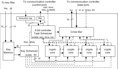
Our crypto-processor (Fig. 1) is built around one task scheduler and several programmable Cryptographic Cores. However, the proposed architecture targets FPGA platform to be as flexible as software components embedded in SDR. By this way, our Multi-Core Crypto-Processor (MCCP) can be updated for security or interoperability reasons. Also, MCCP can take profit of new FPGA partial reconfiguration capabilities to reduce resource consumption and increase its flexibility.
The MCCP is embedded in a much larger platform including one main controller and one communication controller which manages communications going through the radio [17]. MCCP does not generate session keys itself. Keys are generated by the main controller and stored into a dedicated memory. The MCCP is used as a red/black boundary and it provides all necessary cryptographic services needed by an SDR (e.g. se-cure SCA [18]). MCCP architecture is scalable; the number of embedded crypto-core may vary. A four-core architecture has been implemented (Fig. 1). However, more or less than four cores may be implemented according to the communication system requirements.
Proposed MCCP embeds one Task Scheduler which dis-tributes cryptographic tasks to Cryptographic Cores. The Task
Scheduler is implemented using a simple 8-bit controller
which executes the task scheduling software. It manages the
Key Scheduler, the Cross Bar and the Cryptographic Cores. Task Scheduler receives its orders from a 32-bit Instruction Register and returns values to the communication controller
through the 8-bit Return Register. Some signals (Start and
Done) are used to synchronize instruction execution.
Each Cryptographic Core communicates with the commu-nication controller through the Cross Bar, it enables the Task
Scheduler to select a specific core for I/O access. The Key Scheduler generates round keys from the session key stored
in the Key Memory. Before launching the key scheduling, the
Task Scheduler loads the session key ID into the Key Scheduler
which gets the right session key from the Key Memory. To improve system security, the Key Memory cannot be accessed in write mode by the MCCP. In addition, there is no way to get the secret session key directly from the MCCP data port.
Cryptographic Core architecture is further detailed in the
Section 4, the next part deals with the MCCP control protocol.
B. MCCP Control Protocol
As it was explained above, the MCCP receives instructions from the communication controller through the control port. Current release of the MCCP takes a 32-bit instruction as input and returns an 8-bit value as output. Available instruction set
Fig. 1. The MCCP Architecture
allows users to open, close, encrypt or decrypt data packets. When data are available on Crypto Core output FIFOs, the
Task Scheduler sends a Data Available interruption signal to
the communication controller. Once data have been read, the TRANSFER DONE instruction closes the connection.
MCCP executes an instruction in four, non interruptible, steps which are: 1) Write an instruction into the Instruction Register, 2) send a start signal, 3) wait for done signal to be triggered, 4) read returned value from the Return Register. The following list details the available instruction set:
• OPEN Algorithm, Key ID: This instruction is used to open a new channel on the MCCP. It returns either an OK flag and a Channel ID or an error code.
• CLOSE Channel ID: This instruction is used to close an open channel. It returns either an OK flag or an error code.
• ENCRYPT Channel ID, Header Size, Data Size: This instruction is used to encrypt data with a chosen channel.
Header Size and Data Size correspond respectively to
the authenticated only data size and plaintext data size. Before triggering the done signal, the Task Scheduler opens a core fifo in write mode to allow data transmission. It returns either an OK flag and a Request ID or an error flag if no more resources are available.
• DECRYPT Channel ID, Header Size, Data Size: This function works as an inverse-ENCRYPT instruction, since it provides decryption services. It returns either an OK
flag and a Request ID or an error flag if no more resources
are available.
• RETRIEVE DATA: This instruction is used to retrieve data once the Data Available signal has been caught by the communication controller. It returns either an
OK flag or an AUTH FAIL flag if data have not been
authenticated. The Request ID of the corresponding EN-CRYPT/DECRYPT request is also returned. In addition, this instruction configures the Cross Bar to enable I/O
access when an OK flag has been returned.
• TRANSFER DONE: This instruction is used to inform the MCCP that all data have been uploaded/downloaded from/into the fifo after execution of an ENCRYPT, a DE-CRYPT or a successful RETRIEVE DATA instruction.
C. Task Mapping
In the current release of our architecture, incoming packets are processed in their order of arrival as fast as possible. In consequence, no scheduling algorithm are involved in packet processing. Such behaviour allows to maximize the MCCP throughput at the expense of latency in packet processing. However, minimizing latency is essential for real time appli-cations (e.g. voice and video transmission) so this issue will be studied in further works.
Currently, when the Task Scheduler receives either an EN-CRYPT or a DEEN-CRYPT instruction, an incoming packet is forwarded to the first idle core found. If no core is available, it returns an error flag. The improvement of the task mapping algorithm is discussed at the end of this paper.
IV. CRYPTOGRAPHICCORE A. Cryptographic Core Architecture
Architecture of Cryptographic Core is presented on figure 2. On this schematic, dashed lines represent control signals. Each
Cryptographic Core communicates with the communication
controller and other cores through two FIFOs (512× 32bits) and one Shift Register (4×32bits). Cryptographic functions are implemented in the Cryptographic Unit and they can be used through the Cryptographic Unit Instruction Set Architecture. Cipher round keys are pre-computed and stored in the Key
Cache. An 8-bit Controller generates instruction flow
accord-ing to the selected block cipher mode. To save resources, it shares its double port instruction memory with its right neighbouring Cryptographic Core.
Fig. 2. Cryptographic Core Architecture
Inter-Cryptographic Core ports are used to convey tempo-rary data from a core to another. For example, in the case of the CCM mode, the MAC value returned by the CBC-MAC mode needs to be encrypted using the CTR mode. When CBC-MAC and CTR algorithms are computed on two different cores, the inter-Cryptographic Core ports is used to forward the MAC value from the CBC-MAC core to the CTR core.
B. Cryptographic Core 8-bit Controller Design
As said above, Cryptographic Core handles several block cipher operation modes leading to complex control state ma-chines. A more flexible approach is to use a general purpose simple controller to generate instruction flows executed by each Cryptographic Unit. Use of such controller allows us to simplify execution of loop conditions for packet encryption/de-cryption. Because this controller does not perform heavy computations, we use an 8-bit controller providing a simple instruction set. It communicates with the Task Scheduler to receive orders and return execution results.
At prototyping step, a modified 8-bit Xilinx PicoBlaze controller [20] has been used. It embeds a 16× 8-bit register and some arithmetic and logic operators. Each instruction takes two clock cycles to be executed and its instruction memory size is limited to 1024× 18-bit instructions stored into one FPGA ram block. In addition, this controller supports interruption handling. To finish, a custom HALT instruction is used to put the controller into a sleep mode after an instruction is sent to the Cryptographic Unit. The controller wakes up when the Cryptographic Unit triggers the done signal.
C. Packet Processing
Incoming packets are processed in the following way: 1) The Task Scheduler sends an instruction to the 8-bit Controller through the shared memory and triggers a start signal. 2) The
8-bit Controller starts pre-computations needed by the selected
algorithm and loads data from input FIFO once there are
available. 3) Data are processed by blocks of 128 bits and filled into the output FIFO. 4) When all data have been processed, the 8-bit Controller sends a done signal to the Task Scheduler. In order to protect master processor from software attacks (e.g. eavesdropping, spoofing, splicing ), output FIFO is re-initialized if plaintext data does not match the authentication tag. Each FIFO can store a packet of 2048 bytes of data which is sufficient for most of communication protocols.
D. The Available Operation Modes
MCCP can execute GCM, CCM, CTR, CBC-MAC block cipher modes of operation. Available rules for implemented modes of operation are described below:
• Packets from a same channel can be concurrently pro-cessed with different Cryptographic Core.
• Packets from different channels can be concurrently pro-cessed with different Cryptographic Core.
• Any single packet can be processed on any single
Cryp-tographic Core.
• Using inter-core communication port, any single CCM packet can be processed with two Cryptographic Cores. Right mode of operation is selected by the Task Scheduler according to requested channel algorithm and available re-sources. As it is said above, a smartly designed Task Scheduler software must be implemented to use available resources in an efficient way. Further details are given in Section VIII.
V. RECONFIGURABLECRYPTOGRAPHICUNIT A. Cryptographic Unit Architecture
Cryptographic Unit (Fig. 3) provides low level
crypto-graphic primitives. It works sequentially on 128-bit words over a 32-bit datapath. For figure 3 example, a Cryptographic
Unit embeds a 32-bit AES core, a GHASH core and some
arithmetic and logic operators (XOR, adder, comparator). By this way, it can provide support for most block cipher encryp-tion algorithms. In addiencryp-tion, Cryptographic Unit embeds an
Fig. 3. The Cryptographic Unit Architecture
Instruction Decoder and 4× 128 bits Bank Register. A 2-bit counter is also used in order to sequentially reach each four
32-bit sub-word of a Bank Register 128-bit word. A one bit register, S register, is used as a start flag.
On figure 3 example, AES and GHASH cores are both com-pact cores presented in some previously published works. AES
core was developed using P. Chodowiec and K. Gaj work [19]
for FPGA devices. Because AES-CCM and AES-GCM modes only use encryption mode, AES decryption algorithm was not implemented. AES core is implemented using an iterative architecture and the SubBytes transformation [5] uses look up tables. Iterative architecture implies that AES computation time is key size dependant. Computation of one 128-bit block takes 44, 52 or 60 cycles when using respectively 128-bit, 192-bit or 256-bit key sizes.
GHASH core is based on digit-serial multiplier architecture
described in [1]. Digit-serial multiplication is made using 3-bit digits and it is computed in 43 clock cycles. 32-bit Xor/Comparator processing core takes two 16-byte words as input. According to the selected operation mode, it computes either B = (A⊕ B) · mask or set equ flag to 1 if previous result is null. Mask value is a 16-bit word which allows user to mask specific bytes of XOR result.
Inc Core allows 16-bit incrementation by 1, 2, 3 or 4
of a 128-bit word. Finally, 32-bit I/O core manages the communications between FIFOs and the Bank Register.
B. Cryptographic Unit Operation
Cryptographic Unit instructions are executed in seven clock
cycles from start signal rising edge to done signal falling edge. For example, XOR execution steps are detailed below:
1) When Start signal goes high, instruction port value is sampled into the dedicated input register and the S register is set to 1 (i.e. start flag).
2) Decoder immediately decodes the loaded instruction and sends a start signal from the S register to the right processing core start input (i.e. ghash start init,
ghash start finalize, ...). Also, decoder redirects right processing core output to the bank register input and grants read/write access to this core.
3) Processing core sends an Ack signal which validates that
Start signal has been taken into account by resetting the S register.
4) Processing cores rd and/or wr signals go high while data are processed. A high level on rd or wr signals automatically increments the 2-bit counter in order to sequentially reach each 32-bit sub-word of a Bank
Register word. The accessed words are selected by the
two address fields of the instruction register.
5) Once computations are finished a done signal is sent by the processing core to the 8-bit Controller.
Some instructions have a more complex behaviour, the following part deals with the Cryptographic Unit instructions and their particularities.
C. Instruction Set Architecture
Each Cryptographic Unit is controlled thanks to a specific instruction set which is detailed in Table 1. This instruction set provides I/O instructions and low level cryptographic functions such as AES encryption and GHASH algorithm. The 8-bit instructions are composed of a 4-bit operation code and two 2-bit addresses used to address the bank register.
The use of start instructions (i.e. SGFM and SAES) and
finalize instructions (i.e. FGFM and FAES) enables AES and
GHASH algorithms to be computed in background while others instructions (e.g. INC, XOR, ...) are executed. Such mechanism allows to save computation time and therefore improves throughput.
LOAD @A Loads a 128-bit word into the A register.
LOADH @A Loads the computed H constant into the GHASH core.
SGFM @A Computes one iteration of the GHASH algorithm.
FGFM @A Stores the result of the GHASH algorithm into the A register.
SAES @A Encrypts the value stored in the A register.
FAES @A Stores the results of the SAES computation into the A register.
INC @A, I Increments by I the 16 less significant bits of the A register, where I is a 2-bit natural.
XOR @A, @B Computes B = (A XOR B) AND mask.
EQU @A, @B Sets the equ flag to 1 if A = B and 0 else. TABLE I
THECRYPTOGRAPHICUNITISA
VI. IMPLEMENTATION OFCRYPTOGRAPHICALGORITHMS A. General Implementation Rules
Cryptographic algorithms executed by proposed MCCP are implemented with Xilinx PicoBlaze assembler language which is used to generate the Cryptographic Unit instruction flow. Cryptographic Unit instruction is executed in three steps: firstly, the Cryptographic Unit instruction is fetched in the controller, secondly the instruction is written in the
Cryptographic Unit instruction port and finally the controller
waits for execution completion. Performances can be enhanced by pre-fetching the Cryptographic Unit instruction before algorithm execution.
Fetching and pre-fetching steps are made using a LOAD instruction which loads an 8-bit value into the controller bank register. Execution step is made using an OUTPUT instruction which writes an 8-bit value from the bank register to the controller output port. The 8-bit Controller write strobe signal is connected to the Cryptographic Unit start input. To finish, a HALT instruction is used to put the controller in sleep mode until the end of the execution step. Because all the
Cryptographic Unit instructions, except FAES and FGFM,
have a fixed execution time, a HALT instruction may be replaced by two NOP instructions. In this case, the controller does not wait for the predictable done signal and one clock cycle can be saved.
B. Implementation of Block Cipher Modes of Operation
Cryptographic tasks attribution is made in the following way. Firstly, the Task Scheduler selects the cores which will execute the task and generates the needed round keys, then it sends channel and packet parameters to the core (including the algorithm ID, the authenticated only field size, the plaintext field size and the tag length for authenticated channel), finally the Task Scheduler sends a start signal to the cores.
Once an ENCRYPT/DECRYPT instruction has been taken into account, the communication controller sends data into the cores input fifos. Data must be sent in a specific way to be correctly interpreted by the cores. At first, algorithm IV must be filed into the FIFO, then packet data must be filed. To finish, communication controller must append a message authentication tag. Cryptographic Unit only embeds basic operators in addition to AES and GHASH cores, therefore it cannot be used to format the plain text according to the speci-fications of block cipher modes of operation. In consequence,
the communication controller must format data prior to send them to the cryptographic cores.
FIFO buffers can store up to 128 plaintext blocks, so cryptographic algorithm main loops are critical parts of their implementations. Listing 1 shows an example of a piece of code used by cryptographic cores to compute the GCM algorithm main loop. This listing shows how instructions are placed between SAES and SGFM instruction in order to save clock cycles. In this example, OR instructions are used as NOP instructions. To finish, algorithm performances and other results are detailed in the following section.
GCMloop : OUTPUT FAES , i n s t HALT DISABLE OUTPUT SAES , i n s t OR s0 , FF ; NOP OR s0 , FF ; NOP OUTPUT IXOR , i n s t OR s0 , FF ; NOP OR s0 , FF ; NOP OUTPUT SGFM, i n s t HALT DISABLE OUTPUT STORE , i n s t OR s0 , FF ; NOP OR s0 , FF ; NOP OUTPUT INC , i n s t OR s0 , FF ; NOP OR s0 , FF ; NOP OUTPUT LOAD PT , i n s t SUB d l e n g t h , 01 JUMP NZ , GCMloop
Listing 1. GCMloop Body
VII. RESULTS A. Implementation Results
Proposed MCCP has been described with VHDL and syn-thesized using Xilinx ISE Tool. For MCCP hardware imple-mentation, we use a Xilinx Virtex 4 SX35-11 FPGA. With this device, MCCP is able to reach a frequency of 190 Mhz. Only 4084 slices and 26 BRAMs are used.
At lowest level, overall throughput is limited by AES core computation time which depends on AES key size. But, at higher level, throughput is limited by the main loops of block cipher modes. The computation time of these loops may be used to calculate a theoretical maximum throughput for each algorithm. Loop computation times, in cycles, for 128-bit AES-GCM and AES-CCM are equal to:
TGCM loop= TCT R= TSAES+ TF AES= 49
TCCM loop 2cores= TCBC = TSAES+ TF AES+ TXOR= 55
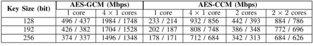
Height cycles must be added to these values for 192-bit keys and height more cycles must be added for 256-bit keys. Then, pre and post loop computations must be taken into account in order to obtain a realistic throughput. It is noticeable that actual throughput depends on packet size, higher throughputs are obtained from larger packets. Table II summarizes these results. For each table II column, the first number denotes the theoretical throughput calculated from loops computation time, while the second number corresponds to the processing time of a 2 KB packet.
Table II shows that AES-CCM 4× 1 cores (4 packets on 4 different cores) provides better throughput than AES-CCM 2× 2 cores (2 packets on 4 cores). This means that packet processing on one core is more efficient than packet processing on two cores. However, latency of the first solution is almost two times greater than latency of the second solution. As a consequence, designers should make scheduling choices ac-cording to system needs in terms of latency and/or throughput. Table III compares architecture performances (i.e. function-alities, area, and throughput) of literature approaches to the proposed one. This table shows that our architecture provides better performances, at the same frequency, than other pro-grammable architectures, while it is still competitive when it is compared to non programmable architectures. In consequence, MCCP architecture seems to provide a good trade-off between flexibility and throughput. The next section presents some preliminary results about MCCP partial reconfiguration.
B. MCCP Partial Re-configuration Preliminary Results
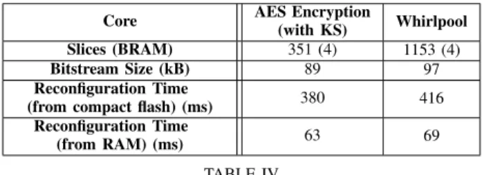
Even if design methodology is not yet mature, most of newest FPGA (Xilinx and Altera) are partially reconfigurable. MCCP flexibility can be further improved through partial reconfiguration of the Cryptographic Unit. At the time of writing this paper, we implemented partial reconfiguration on a Xilinx Virtex 4 FPGA. Implemented cryptographic algorithms are the AES encryption algorithm and the Whirlpool hashing algorithm. The reconfigurable area embeds 1280 slices and 16 BRAM. Table IV details the measured preliminary results.
Core AES Encryption
(with KS) Whirlpool
Slices (BRAM) 351 (4) 1153 (4)
Bitstream Size (kB) 89 97
Reconfiguration Time
(from compact flash) (ms) 380 416
Reconfiguration Time
(from RAM) (ms) 63 69
TABLE IV
PARTIALRECONFIGURATIONRESULTS
Reconfiguration time results show that caching of bitstream is needed to obtain the best performances. In addition, mag-nitude of the reconfiguration times does not allow to consider real-time partial reconfiguration. However, partial reconfigura-tion may be used for occasional reconfigurareconfigura-tions. For example, in a first time, a key exchange algorithm may be loaded into the
Cryptographic Unit then, in a second time, a data encryption
algorithm may be loaded. In addition, the reconfiguration of one part of the FPGA does not prevent others parts to work. This is valuable in the case of on-line hardware updates for example.
VIII. DISCUSSION
Like with classical MPSoC, to allow maximum throughput, incoming data streams have to be assigned to idle
Crypto-graphic Cores. Similarly, CryptoCrypto-graphic Cores have to be
released after a stream has ended. The assignment procedure has also to cover loading of the correct Cryptographic Core program and Cryptographic Unit configuration. Besides sim-ple assignment of streams to idle Cryptographic Cores, it must also be possible to priorize certain streams over others to allow some sort of quality-of-service. Nevertheless, system security has to be continually enforced. As a consequence, significant works have to be done to develop secure operating system able to manage stream assignment and MCCP reconfiguration.
IX. CONCLUSION ANDFUTUREWORKS
This work shows that the multi-core architecture presented in this paper provides a good trade-off between flexibility and throughput. Flexibility and performances are obtained by using a hybrid design where low level cryptographic primitives are implemented in hardware while high level block cipher modes are implemented in software. Its 1.7 Gbps throughput makes it particularly suitable for medium rate multi-channel commu-nication systems. Proposed MCCP supports CTR, CBC-MAC, CCM and GCM block cipher modes which are commonly used in communication systems. AES core may be easily replaced by any other 128-bit block cipher (such as Twofish) according to the user needs. It is noticeable that partial reconfiguration, may be used to do this task.
In future works, task scheduling will be improved and partial reconfiguration will be fully implemented to obtain a highly flexible and efficient architecture.
ACKNOWLEDGEMENT
This work is in part supported by the French DGA (General Armaments Directorate) and by the University of Bordeaux. The views expressed in this paper are those of the authors and cannot be regarded as stating an official position of the DGA or the French DoD.
REFERENCES
[1] S. Lemsitzer, J. Wolkerstorfer, N. Felber, and M. Braendli, “Multi-gigabit gcm-aes architecture optimized for fpgas,” in CHES ’07:
Pro-ceedings of the 9th international workshop on Cryptographic Hardware and Embedded Systems. Berlin, Heidelberg: Springer-Verlag, 2007, pp.
227–238.
[2] A. Hodjat and I. Verbauwhede, “Area-throughput trade-offs for fully pipelined 30 to 70 gbits/s aes processors,” IEEE Transactions on
Computers, vol. 55, pp. 366–372, 2006.
[3] A. Aziz and N. Ikram, “An fpga-based aes-ccm crypto core for ieee 802.11i architecture,” I. J. Network Security, vol. 5, no. 2, pp. 224–232, 2007.
[4] R. Buchty, N. Heintze, and D. Oliva, “Cryptonite - a programmable crypto processor architecture for high-bandwidth applications,” in
Or-ganic and Pervasive Computing - ARCS 2004, ser. Lecture Notes in
Computer Science, S. B. . Heidelberg, Ed., vol. 2981/2004, 2004, pp. 184–198.
Key Size (bit) 1 coreAES-GCM (Mbps)4× 1 cores 1 core 4× 1 coreAES-CCM (Mbps)2 cores 2× 2 cores 128 496 / 437 1984 / 1748 233 / 214 932 / 856 442 / 393 884 / 786 192 426 / 382 1704 / 1528 202 / 187 808 / 748 386 / 348 772 / 696 256 374 / 337 1496 / 1348 178 / 171 712 / 684 342 / 313 684 / 626
TABLE II
MCCP ENCRYPTIONTHROUGHPUTS AT190 MHZ(THEORETICAL/2 KB PACKET)
Implementation Platform Programmable Algorithm Throughput (Mbps/MHz) Frequency (MHz) Slices (BRAMs)
Cryptonite [4] ASIC Yes ECB 5.62 400 —
Celator [15] ASIC Yes CBC 0.24 190 —
Cryptomaniac [16] ASIC Yes ECB 1.42 360 —
A. Aziz et al. [3] x3s200-5 No CCM 2.78 247 487 (4)
S. Lemsitzer et al.[1] v4-FX100 No GCM 32.00 140 6000 (30)
Our work v4-SX35-11 Yes (AES modes) GCM/CCM 9.91 / 4.43 190 4084 (26)
TABLE III PERFORMANCECOMPARISON
[5] FIPS-197, NIST Std., 2001. [Online]. Available: http://csrc.nist.gov/ [6] Special Publication 800-38C, NIST Std., 2004. [Online]. Available:
http://csrc.nist.gov/
[7] Special Publication 800-38A, NIST Std., 2001. [Online]. Available: http://csrc.nist.gov/
[8] FIPS 113, NIST Std., 1985.
[9] D. Whiting, R. Housley, and N. Ferguson, “Counter with cbc-mac (ccm), submission to nist,” NIST, Tech. Rep., 2002.
[10] Special Publication 800-38D, NIST Std., 2007. [Online]. Available: http://csrc.nist.gov/
[11] A. Satoh, Takeshi, and T. Aoki, “High-speed pipelined hardware archi-tecture for galois counter mode,” in Information Security, ser. Lecture Notes in Computer Science, S. B. . Heidelberg, Ed., vol. 4779/2007, 2007, pp. 118–129.
[12] S. Wang, “An architecture for the aes-gcm security standard,” Master’s thesis, University of Waterloo, 2006.
[13] K. Vu and D. Zier, “Fpga implementation aes for ccm mode encryption using xilinx spartan-ii,” Oregon State University, Tech. Rep., 2007. [14] E. L´opez-Trejo, F. Rodr´ıguez-Henr´ıquez, and A. D´ıaz-P´erez, “An fpga
implementation of ccm mode using aes,” in ICISC, 2005, pp. 322–334. [15] D. Fronte, A. Perez, and E. Payrat, “Celator: A multi-algorithm cryp-tographic co-processor,” in Proc. International Conference on
Recon-figurable Computing and FPGAs ReConFig ’08, Dec. 3–5, 2008, pp.
438–443.
[16] L. Wu, C. Weaver, and T. Austin, “Cryptomaniac: a fast flexible architecture for secure communication,” in ISCA ’01: Proceedings of the
28th annual international symposium on Computer architecture. New York, NY, USA: ACM, 2001, pp. 110–119.
[17] M. Grand, L. Bossuet, G. Gogniat, B. L. Gal, and D. Dallet, “A reconfig-urable crypto sub system for the software communication architecture,” in Proceedings MILCOM2009, 2009.
[18] Security Supplement to the Software Communications Architecture
Specification, April 30, 2004, JTRS Std. 2.2.1, April 2004. [Online].
Available: http://sca.jpeojtrs.mil/
[19] P. Chodowiec and K. Gaj, “Very compact fpga implementation of aes algorithm,” in CHES 2003. Berlin Heidelberg: Springer-Verlag, 2003, pp. 319–333.
[20] Picoblaze user resources. Xilinx. [Online]. Available: http://www.xilinx.com