Thèse de Maitrise
Mahsa Naghavi
Studying the cytomechanic aspects of pollen tube growth
behavior using Lab-On-Chip technology
Membres du comité conseil: Mohamed Hijri Anja Geitmann Muthukumaran Packirisamy Printemps 2014 Université de Montréal Faculté des arts et des sciences Département de sciences biologique
Table of content
List of figures ………..4
Literature review ………..……6
1. Plant cell morphogenesis ………...6
1.1. Tip Growth ………...……….…...10
1.2. Directional Polar Growth ………..………...14
2.1. Cytoarchitecture of the pollen grain ………...……….18
2.2. The pollen tube ………...20
3. Sexual plant reproduction ………24
4. Invasive growth ………...………26
5. Objectives ………28
Chapter 1. Development of the microfluidic platform TipChip ……….….29
Summary ……….30
1.1. Introduction ………..30
1.1.1. Microfluidic devices imitating in-vivo conditions ……….……...33
1.1.2. Design and Fabrication ………..……….. 34
1.2. Design and fabrication of LOC platform ……….40
1.4. Effects of microchannel dimensions on pollen tube growth ………..……..43
Chapter 2: Invasive force ……….………...45
Summary ……….45
2.1. Introduction ……….……….46
2.1.1. Device design ……….………...49
2.2. Material and methods ……….………..51
Pollen collection and germination . ……….…….….…..51
Fabrication of microfluidic device ……….……….52
Microscopy ………..………52
2.3. Results and Discussion ………..………...53
Fabrication of the microfluidic platform and invasion of narrow spaces ……....53
Pollen tube navigation via microgaps ………..………54
Effect of mechanical constraint on growth rate ………..……….58
2.5. Calculation of the dilating force of the pollen tube
Finite Element Simulation ………..………...….60
2.6. Discussion ………...………..61
Chapter 3: Compatibility of LOC devices for high-resolution microscopy ………..65
Summary ……….……65
3.1. Introduction ……….……….……66
3.2. Material and methods ……….…..68
Microfluidic network design ………....………….…..68
Pollen culture and germination ……….……..68
Imaging ………..………..69
Vesicle labeling ………..…….69
3.3. Results ………..………70
TipChip and high-resolution imaging with Nomarski and fluorescence microscopy ………..……….70
3.4. Discussion ………...73
6. Future work ……….………75
6.1. The ability of pollen tubes to pass through the air–liquid interface and elongate in air ……….………75
6.2. Directional memory ………..77
7. General Discussion & Perspectives ………..…...80
Invasion of narrow spaces ………..……….81
List of figures
Figure 1. Schematic taken from Kroeger et al (2009) illustrating the directional movement of vesicles and the orientation of the actin filaments in the apical region of a pollen tube.
Figure 2. Schematic presentation of pollen grain wall.
Figure 3. Scanning electron micrograph of Arabidopsis thaliana pistil with false colors (Bou Daher, 2011).
Figure. 4. The pistil of Camellia and the pollen tube passageway from stigma to ovule. Figure 5. Cellular structure of the pollen tube.
Figure 6. Micro-device for growing pollen tube.
Figure 7. Basic design of the multichannel TipChip platform.
Figure 8. Microchannel fabrication using two high-resolution methods. Figure 9. LOC fabrication.
Figure 10. Presentation of LOC.
Figure 11. Micrographs of the designs used to investigate the effect of microchannel width and depth on the growth of pollen tube (Agudelo, et al., 2013a).
Figure 12. Fabrication of platform for measuring invasion by pollen tubes using microgaps. Figure 13. Schematic presentation of interaction between pollen tube and microgap.
Figure 14. Growth of Camellia pollen tube through microgaps.
Figure 15. Different behavior of Camellia pollen tube through microgap.
Figure 16. Changing the growth velocity of Camellia pollen tube in the microgaps. Figure 17. The male germ passage across a microgap.
Figure 18. Testing of the TipChip with Nomarski optics and fluorescence. Figure 19. Growth of Camellia pollen tube in air chamber of TipChip device. Figure 20. Presentation of the LOC for tip memory of pollen tube.
Literature review
1. Plant cell morphogenesis
There are several structural differences between animal and plant cells, one of the most significant being the presence of a polysaccharide wall outside of the plasma membrane of plant cells. Plant development is based on three fundamental processes of cell expansion, cell division and cell differentiation. Since walled cells such as those of plants, algae and fungi do not crawl or migrate; the overall expansion of the cell is the only way for a cell to reach other locations in the organism. Cellular expansion is also fundamental in the generation of the phenotype of the adult plant (Fowler and Quatrano, 1997; Smith and Oppenheimer, 2005; Geitmann and Ortega, 2009). During expansive growth, both the cell size and the shape of the cell change. During differentiation of the cell, the volume of meristem cells increases between 10-1000-fold up to 30 000-fold (in xylem vessels), depending on the type of the cells (Veytsmann and Cosgrove, 1998; Cosgrove, 2005). The expansion is the result of a mechanical procedure that balances the external and internal forces and causes the cell wall to be deformed (Geitmann and Ortega, 2009). It is driven by the hydrostatic pressure called turgor, which is generated through differences in osmotic pressure. Turgor pressure is non-vectorial and hence is applied onto the cell wall equally in all directions (Mathur, 2006; Geitmann and Ortego, 2009). Therefore, cell expansion in cells with uniform and isotropic cell walls will always result in a spherical shape. Any other shapes are generated by modulating cell wall properties to be either non-uniform, anisotropic or both. The regulation of cell wall mechanical properties is therefore crucial for the generation of complex shapes such as those of the jigsaw puzzle shaped cells of the leaf epidermis or the longitudinal shape of shoot and root cells (Mathur, 2006). These cylindrical cell shapes are generated by a largely diffuse growth pattern, as is the case in the roots and shoots (Castle, 1955; Green, 1963; Chen, 1973; Shaw et al., 2000). However, in this case
growth has to occur in highly anisotropic manner.
In plant cell morphogenesis, expansive growth is regulated by three important features; (i) the polysaccharidic network forming the cell wall in plants and fungi providing the mechanical structure, (ii) agents modulating the mechanical properties of this network such as newly added polysaccharides, proteins, pH and Ca2+). (iii) the magnitude of the internal hydrostatic pressure
caused by turgor (Dumais et al., 2006; Geitmann and Ortega, 2009).
The morphogenesis of plant cells with more complex geometry typically entails the formation of localized outgrowths. These are generated through local modulation of the cell wall properties (Cosgrove, 2000), which in turn is regulated by the underlying cytoskeletal mesh which controls local cell wall assembly (Hepler et al., 2001; Mathur, 2004). A spatially confined softer region of the cell wall causes will result in a local swelling which can be the beginning of polar cell expansion and formation of a protuberance (Mathur, 2006). The local cell wall softening and expansion leads morphogenetic processes such as leaf development at the shoot apical meristem and root hair formation from the root epidermis (Hamant et al., 2008).
The best examples of local wall expansion are the tip-growing cells, such as fungal hyphae, root hairs, and pollen tubes. In these cells, growth at the tip happens when the material for the cell wall and membrane expansion are secreted and discharged at the very tip or apex of the cells (Fowler and Quatrano, 1997; Bove et al., 2008). In plant tip-growing cells that are immobile, morphogenesis and development is regulated at the cortical area. The spatial control of cell expansion and cell division are established in these cortical domains. In plant tip-growing cells, cortical domains are the main keys of directional signals for cell polarity and cell division. Typically, a directional signal helps (causes) the stimulation of an asymmetrical cortex or membrane-associated, called a cortical domain, where the cell wall material is delivered via the cytoskeletal arrays (Fowler and Quatrano, 1997). Therefore, the spatial regulation of plant
cell morphogenesis is mediated by the cytoskeleton, plasma membrane and the secretion of material to the targeted region of cell wall for expansion (Fowler and Quatrano, 1997; Kropf, 1992).
Cell expansion is the result of both the increase in cell size and the change in cell shape (Cosgrove, 2005). In the initiation of polarized growth, actin plays a key role which has clearly been illustrated during rhizoid initiation in spherical fucoid zygotes (Alessa et al., 1999), as well as the actin accumulation in tip growing cells (pollen grain germination and root hairs) (Baluska et al., 2000; Gu et al., 2003), during the initiation of trichomes (leaf hairs) (Mathur et al., 1999). Consistent with this notion, the application of an actin inhibitor leads to diffusive and abnormal rhizoid formation in fucus zygotes (Habel et al., 2003), inhibition of pollen tube formation in germinated pollen grains (Vidali et al., 2001), as well as failing to launch the tip domain in Arabidopsis trichoblasts (Baluska et al., 2000).
In plant cell morphogenesis, the interaction between the cytoskeleton, plasma membrane and the cell wall was studied to observe cell expansion triggered by directional light in the zygotes of fucoid algae (Kropf, 1992). The signal from the directional light causes an interaction between actin microfilaments and the plasma membrane. This interaction assists in the transmission of a directional trigger in the polar growth reorientation of the cell. This directional signal builds a cortical site for redirection of secretory vesicles from a symmetrical pattern to an asymmetrical distribution (Fowler and Quatrano, 1997).
Studies report that in tip-growing cells of bacteria, budding yeast and animal cells (neurons) the expansion occurs in response to directional triggers of internal or external origins (Horvitz & Herskowitz, 1992; Drubin & Nelson, 1996; Gönczy & Hyman, 1996). In these types of cells, as well, the directional signal requires the asymmetrical exocytosis of material required for cell growth at either a cortex or a membrane. The macromolecules to be targeted (such as proteins) are shipped to the cortex or membrane via a cytoskeletal system. The cytoskeleton has a central
role for controlling both the growth of plant cell and its spatial regulation in directing the cell wall material deposition. In higher plants, as in yeast and Fucus (a marine brown algae), the localized cellular expansion could be as follow, firstly by chosen a cortical site, which this site would help to guide the expansion of the neighbouring cell wall. Secondly, the secretion that is necessary for the modification of the wall at this cortical site (Fowler and Quatrano, 1997).
The major structural component in the cell wall that regulates expansion is cellulose, which is synthesized by complexes of enzymes located in plasma membrane. The cellulose microfibril arrangement is important for determining the pattern of cell wall expansion, and it has an important relationship with cortical microtubule organization in growing cells. The arrangement of the microtubules is parallel to the main orientation of the microfibrils, in most plant cells (Pierson et al., 1986). The orientation of the cortical microtubules and cellulose microfibrils controls the anisotropic expansion (Wiedemeier et al., 2002). When pharmacological agents or mutation disrupts the cortical microtubules, the deposition pattern of cellulose microfibrils is also interrupted. This disrupts the normal deposition pattern, where might cause the breakdown of the tissue boundaries (Wiedemeier et al., 2002). The parallel alignment of cellulose causes anisotropic expansion since it reduces expansion in the direction parallel to the fibrils (Green, 1980; Taiz, 1984). Therefore, when cellulose microfibrils are not aligned in parallel any longer, the anisotropic expansion changes to isotropic expansion (Wiedemeier et al., 2002).
Unlike cellulose and callose (a related polymer), all other components required for cell wall assembly are delivered to the wall through secretion. These secreted components include a variety of carbohydrates, needed for cross-linking of the cellulose microfibrils; and the enzymes that catalyze both breakage and reforming of cross-links (Schopfer, 2006; Chebli and Geitmann, 2007; Geitmann and Ortega, 2009; Keegstra, 2010). The cytoskeleton is important for cell expansion as it controls secretion in space and time (Smith and Oppenheimer, 2005; Schopfer, 2006; Geitmann and Ortego, 2009; Bove et al., 2008).
1.1. Tip Growth
In plant cells, two main types of growth can be distinguished: diffuse and tip growth. In diffuse growth the surface of walled cells expands uniformly over the entire cell surface resulting in a spherical or polyhedral shape (such as potato tuber parenchyma), whereas the growth region of tip growing cells is confined to the extremity of the cell, resulting in a more complex cell shape that in this case is cylindrical. Tip growth is extremely polarized, and the incorporation of new cell wall material as well as the wall expansion is localized. Typical tip-growing cells in plants are pollen tubes and root hairs, and in animals are neurons. The investigation of the mechanical principles governing tip growth has helped us to understand how plant cell morphogenesis functions in general (Mathur, 2006).
In general, plant cell growth relies on interplay between turgor pressure, water absorbance and changes in mechanical properties of the cell wall through modulation of its composition. The turgor pressure applies the necessary force to deform the existing cell wall, which causes the expansion of the cell (Geitmann and Ortega 2009). Simultaneously to wall expansion, new cell wall material needs to be inserted to prevent bursting that would eventually result from the turgor induced stretching of the existing wall. In tip-growing cells the assembly must occur at very fast rates to sustain this rapid process. Cell wall material is quickly transported to and secreted at the tip by secretory vesicles (Bove et al., 2008).
As is typical for tip growing cells, the apical cytoplasm of a pollen tube contains a huge number of secretory vesicles (Chebli and Geitmann, 2007; Bove et al, 2008). This spatially confined deposition mechanism together with the application of the turgor pressure inside the cell causes the non-uniform mechanical deformation of the cell wall materials, which in turn generates directed cell expansion (Dumais et al, 2006). The wall expansion involves simultaneous secretion of new material and wall deformation driven by the turgor pressure (Dumais et al., 2006). These two main processes are combined in a model of cell
morphogenesis for tip growing cells (Dumais et al. 2006). The turgor driven expansion of the cell wall in tip growing cells is limited to a very small region of the cellular surface, the apex. Since turgor pressure is a scalar factor, this spatial confinement is ensured by a spatial gradient of wall deformability (Chebli and Geitmann, 2007; Fayant et al., 2010). As is the case for diffusely growing cells, tip-growing cells have a stiff wall in the non-growing region to maintain the shape of cell (Cosgrove, 2000) caused by the polar distribution of the cell wall material. The distal deposition of cellulose and callose contribute to the rigidification of the wall, forming the cylindrical shank of the tube. The bulk of the wall material delivered by vesicles is in the form of methyl esterified pectins which, after their exocytosis mature through de-methyl esterification by pectin methylesterase and their subsequent gelation by calcium ions in the shoulders of the apex. This gelation increases the mechanical strength of the pectic material (Geitmann and Steer, 2006, Chebli and Geitmann, 2007). Therefore, the apical cell wall of the pollen tube is rich in methylesterified pectin, while the shank is constructed by two or three cell wall layers of callose, cellulose and de-esterified pectins (Geitmann and Steer, 2006; Aouar et al., 2010; Fayant et al., 2010). The callose layer is deposited between the plasma membrane and the pectin layer in the distal region of the tube (Parre and Geitmann, 2005). The continuous and highly targeted exocytosis of methyl esterified pectin yields to the turgor pressure (Geitmann and Steer, 2006; Chebli and Geitmann, 2007; Fayant et al., 2010). This gradient of (esterified/de-esteried) pectin in mechanical properties and the spatially controlled process of exocytosis are crucial for morphogenesis of a perfectly cylindrical cell (Fayant et al. 2010).
The stiffening in the shank region ensures that the pollen tube expands and elongates only at the tip of the cell (Fayant et al., 2010). In walled cells it is possible to stop cell enlargement while wall deposition is maintained for some time leading to local thickening of the cell wall (Roy et al., 1999). These authors studied the uncoupling of exocytosis and elongation, via
cytoplasmic calcium concentration and extracellular calcium in Lilium longliflorum pollen tubes. The growing pollen tubes were treated with phenylglycoside ((β-D-Glc)3), which inhibits
growth but not secretion. The arabinogalactan proteins (AGPs) secrete into the tip of pollen tube through Golgi vesicles, the binding of phenylglycoside ((β-D-Glc)3) to these proteins blocks the
fusion of new cell wall materials. This phenomenon changes the balance of the exocytosis process from the extension growth in the pollen tube (Roy et al., 1999). Although the extension of pollen tubes in lily is inhibited, the cell wall components build up, and the exocytosis continues with a disorganized pattern that was suggested to be a result of dynamic changes of calcium ion (Roy et al., 1999).
Germination and elongation of pollen in vitro requires the presence of calcium in the medium (Bou Daher et al., 2009; Brewbaker and Kwack, 1963). The calcium ion is taken up primarily at the apex of the tube, and as a consequence, growing pollen tubes, but not non-growing tubes, display a steep gradient of cytosolic free calcium extending from the apex (high Ca2+ concentration) towards the shank (low concentration) (Malhó et al., 1995; Pierson et al., 1994). To investigate the role of calcium, the pollen tubes also were treated with caffeine, a growth inhibitor that reduces the influx of calcium (Ca2+) ion ([Ca2+]i). Ca2+ is a fundamental element in the growth of pollen tube, and the elongation of a pollen tube depends on cytosolic gradient of [Ca2+]i (Malhó et al., 1994; Miller et al., 1992; Pierson et al., 1994). Roy et al. (1999) observed the elongation inhibition of tubes and slight thickening of the cell wall at the apex of tube when they treated the pollen tubes with both substances (caffeine and phenylglycoside). In the treated cells, the calcium gradient of the tip collapses and the calcium influx decreases at the tip, where cell wall thickening occurs (Roy et al., 1999). Inversely, if exocytosis is inhibited while turgor is maintained, the wall may rupture (Dumais et al. 2006).
Disruption of this cytosolic calcium gradient through BAPTA buffer (1,2-bis(o-aminophenoxy)ethane- N,N,N',N'-tetra acetic acid)) and blockage of calcium channels result in
growth inhibition (Pierson et al. 1994). In lily pollen tubes, the calcium gradient has been measured to decrease from 3.0 µM at the apex to almost 0.2 µM within the distance of 20 µm. The influx of calcium was measured to be between 1.4-14 pmol/cm2/s (Pierson et al., 1994). The decrease of the calcium concentration in the shank of the tube has been attributed to the uptake by the endoplasmic reticulum or mitochondria (Pierson et al., 1994; Geitmann and Emons, 2000; Chebli and Geitmann, 2007; Battey and Blackbourn, 1993).
Because of the extremely rapid growth in pollen tubes, all processes involved in regulating it must be precisely regulated and fine-tuned. Turgor needs to be maintained and growth rate regulated, while the delivery of vesicles must be controlled to ensure sufficient pectin molecules are available to sustain expansion (Chebli and Geitmann, 2007, Bove et al., 2008, Fayant et al., 2010). Cell wall mechanical resistance controls expansion and therefore the self-similar pattern of shape generation that ensures the geometry of the apex remains constant in time despite its continuous advancement. However, the control of the externally positioned cell wall and its non-uniformly distributed properties eventually lie in the process that is responsible for material delivery. The delivery and targeting of vesicles carrying cell wall material by the actin cytoskeleton has been found to be crucial (Taylor and Hepler, 1997; Geitmann and Emons, 2000; Kovar et al., 2000; Vidali et al., 2001). Actin filaments have to continuously polymerize in order to keep up with the elongating tip. In addition to delivering vesicles, actin filaments organize the apical cytoplasm (Vidali et al., 2001). Remarkably, pharmacological inhibition of actin polymerization inhibits pollen tube growth at drug concentrations that are lower than those required to inhibit long-distance organelle transport (Gibbon et al., 1999; Vidali et al., 2001; Geitmann and Emons, 2000). These findings indicate that actin dynamics is essential for the process of pollen tube expansive growth. The actin cytoskeleton is a key element linking signal perception pathways and subsequent cellular response. Therefore, there is a potential connection
between cell wall expansion, vesicle trafficking and biochemical pathways of all which are involved in the response triggered by a directional signal.
The cytoskeleton of the pollen tube mainly consists of actin filaments and microtubules. These filamentous proteins are oriented in approximately longitudinal or slightly helical manner relative to the long axis of the cell (Geitmann and Emons, 2000; Chebli and Geitmann, 2007). Both cortical cytoplasm and endoplasm contain actin and transport occurs in opposite directions in these two cellular regions (Geitmann and Emons, 2000; Chebli and Geitmann, 2007). Consistent with the fact that myosin moves only in one direction of the polar actin filaments, the opposite movement directions are caused by opposite arrangement of the actin arrays in the central and cortical cytoplasm (Lenartowska and Michalska, 2008; Kroeger et al., 2009). Microtubules are typically located in cortical arrays that are arranged longitudinally (Pierson & Cresti, 1992). In most tip-growing cells, such as pollen tubes and hyphae, nuclear organization, migration and position are controlled by the microtubules (Joos et al., 1994; Owens and Morris, 1991; Ǻström et al., 1995; Kaminskyj and Heath, 1996). It was found that microtubule degradation (by oryzalin or colchicine) had no significant effect on the capability of pollen tubes to grow or to invade a mechanical obstacle (Gossot and Geitmann, 2007). However, actin destabilization by latrunculin-B (Lat-B) decreases the ability of pollen tube to invade a stiff medium (Gossot and Geitmann, 2007).
1.2. Directional Polar Growth
To reach their targets, tip-growing cells have to change their direction of growth on their path. Neuron cells need to reach targets that are millimeters or centimeters away through other tissues (Dickson, 2002). Root hairs elongate inside the complex geometry of the soil particles to uptake water and minerals for nourishing the plants (Pei et al., 2012). Pollen tubes need to reach the ovary for releasing the sperm cells for fertilization (Taylor and Hepler, 1997; Erbar, 2003;
Shukla et al., 1998). This path can be many centimeters long.
Changing the directional growth of the tip-growing cell requires a deviation from the radially symmetrical assembly pattern of the cell wall at the tip (Geitmann and Steer, 2006), which is thought to be achieved by targeting secretory vesicles asymmetrically. The logistics of vesicle transport, mediated by the actin cytoskeleton (Shimmen and Yokota, 2004), a crucial element in the cellular response to an external signal. The role of actin cytoskeleton is fundamental for the turning events in all these tip-growing cells (Mattila and Lappalainen, 2008; Isbister and O’Connor, 2000; Zheng et al., 1996; Baluska et al., 2000; Cheung and Wu, 2008; Bou Daher and Geitmann, 2011).
Neurons consist of an axon and dendrites to pass chemical or electrical signals through an organism. Axons are able to extend to remote targets by making branches and dendrites are thinner branches that elongate for few hundred micrometres. The signals are transferred to another dendrite or target via synapses. The extension of axons and dendrites occurs at the extremity, the growth cone (Dickson, 2002; Mattila and Lappalainen, 2008). Growth cones can find the correct path toward their targets and they are able to change the direction during elongation. Turning requires the motility of the actin cytoskeleton. There are two groups of actin filaments in the neuronal growth cone: dense parallel bundles of outward oriented filaments (in the plasma membrane of the cell) called filopodia, and a network of loose actin filaments (Dickson, 2002). Filopodia are very important in cell motility in dendritic spines (Dickson, 2002; Mattila and Lappalainen, 2008). During turning, the filopodia extend asymmetrically prior to the growth cone reorientation (Isbister and O’Connor, 2000). In the absence of filopodia, the growth cone is disoriented (Zheng et al., 1996).
In plants, root hairs develop in four steps: selections of a bulge site on the surface of the trichoblast, bulge initiation, tip growth of the hair and maturation. The actin cytoskeleton has an important role in all these steps (Pei et al., 2012). At the location on the trichoblast surface,
where initiation of the bulge occurs, the actin filaments accumulate and extend extremely toward the bulging apex to form the actin meshwork (Baluska et al., 2000). The elongation of root hairs also is limited to the tip, to which secretory vesicles are shipped via the actin cytoskeleton. The role of actin filaments is therefore similar as in pollen tubes (Cheung and Wu, 2008) with an important function in vesicle and organelles movement (Pei et al., 2012). Consistent with the inverse fountain streaming pattern, the cytoplasmic structures in the pollen tube appear to be aligned parallel to the long axis of the tube except in the tip region, where they are more randomly distributed (Kroeger et al., 2009). Contrary to the high stability of actin in muscle cells (Vartiainen et al., 2000; Vartiainen et al., 2002), the actin cytoskeleton in rapidly growing plant cell (pollen tubes) is very dynamic.
The organization of the cortical cytoplasm and the regulation of vesicle trafficking in the tip of the pollen tube are controlled by the apical and subapical actin arrays (Kroeger et al., 2009) (Figure 1) which continuously polymerizes to keep up with pollen tube elongation. Remarkably, in the pollen tube, only a small portion of the actin is present in filamentous form and a huge pool of polymerizable monomers are available for the continuously ongoing polymerization of the actin array at the growing end of the cell (Staiger et al., 2010).
The vesicle transfer and movement in the pollen tube from the Golgi bodies to the tip is a myosin-mediated process that requires energy in form of ATP (Bove, et al., 2008; Shimmen and Yokota, 2004), whereas microtubules are not required for organelle transport in the pollen tube (Åström et al., 1995).
The activity of calcium channels, actin dynamics and the concentration of cytosolic calcium are symmetrically distributed around the central axis going through the pole of the tube, in a growing pollen tube (Bou Daher and Geitmann 2011, Malhó et al., 1992). Bou Daher and Geitmann (2011) analysed the temporal sequence of events leading up to a change in growth direction, using a galvanochamber setup. Both the vesicle pool and actin fringe were found to tilt prior to a visible change in growth geometry suggesting the actin polymerization occurs at different speeds in the two sides of the pollen tube. Actin polymerization seemed either to be slowed down in the cathodal side or enhanced in the anodal side to allow the tube to bend
Figure 1. Schematic taken from Kroeger et al., (2009) illustrating the directional movement of vesicles and the orientation of the actin filaments in the apical region of a pollen tube. Vesicles are delivered on actin cables and the finer actin filaments of the apical fringe into the apical region, where they are released into the annulus-shaped zone of apical cytoplasm (vesicle delivery zone). Those vesicles that contact the plasma membrane will undergo exocytosis, whereas unsuccessful vesicles will be moved backwards towards the centre of the cone-shaped vesicle pool. Solid arrows represent the movement of actin-myosin-guided vesicles, and dashed arrows represent those movements most probably governed by diffusion. This schematic is not drawn to scale and no other organelle or the cell wall is shown.
towards the cathode (Bou Daher and Geitmann 2011). This asymmetric growth activity is likely regulated by actin binding proteins, for example ADF7 and ADF10 (Bou Daher et al., 2011).
2.1. Cytoarchitecture of the pollen grain
Pollen grains vary in size (from 10 to 100 µm); shape (round, oval, disc, bean-shaped and filamentous); color (ranging from white, cream, yellow or orange to green and blue); surface structure of the cell wall (from smooth to spiky) and the number and position of germinating apertures (Wodehouse, 1928; Sporne, 1972; Hill and Lord, 1987; Moore et al., 1991). In angiosperms (flowering plants), the mature pollen grain is comprised of two or three cells, depending on the species. Most of the volume of the grain is occupied by the vegetative cell and surrounded by its cytoplasm is either a generative cell (two-celled pollen) or two sperm cells (three-celled pollen). In two-celled pollen the generative cell will divide into two sperm cells during pollen tube growth. The pollen grain is the result of meiosis followed by several mitotic cell divisions and all cells are therefore haploid (Edlund et al., 2004; Yang and Sundaresan, 2000).
The pollen grain is surrounded by a wall that in the mature pollen grain consists of three principal strata (layers) (Figure 2). 1) The external layer is comprised of several ingredients including lipids, pigments, proteins and scented complexes, which cover the holes on the pollen grain exine. 2) The outer wall (exine) is thick, rigid, multilayered and composed of the chemically a resistant polymer, sporopollenin. This layer is interrupted at the germination pores, the apertures. The thick outer layer of the exine lies over the inner layer that extends around whole pollen grain surface and is cutinized all over the pores. The outer exine layer consists mainly of stable biopolymers containing fatty acids. The inner layer of the exine is composed of callose, cellulose and hemicelluloses. The inner layer is cutinized, relatively thick, and uniformly structured except for the germinal aperture where it is broken into granules or
platelets. These layers protect the vegetative and generative cell against mechanical and chemical damage, as well as from environmental conditions such as ultraviolet radiation of the sun. 3) The inner wall of pollen grain (intine) is sometimes multilayered and consists mainly of cellulose. It can be of varying thickness, depending on the species, and it typically is much thicker in the apertural region. Although a thin layer of pectin covers most of the pollen grain surface, around the aperture region a thicker layer of pectin exists. The pectic layer is important during pollen grain hydration since it aids with water absorption. The resulting swelling of the grain can fracture the exine at the aperture during the initial phase of germination (Edlund et al., 2004; Zinkl et al., 1999; Nakamura and Miki-Hirosige, 1985; Ehrlich, 1959; Wodehouse, 1928).
Figure 2. Schematic presentation of pollen grain wall. The thick exine forms the outer wall of pollen grain. A thin layer of intine is located beneath the exine. (http://www.tutorvista.com/content/biology/biology-iv/flowering-plants-reproduction/sexual-reproduction.php)
2.2. The pollen tube
The pollen tube delivers the male gametes into the ovule to reach the female gametophyte. Successful growth and tube elongation, therefore, provides a fundamental link between fertilization and seed setting during reproduction. The distance between the stigma and ovule varies depending on the species and can be tens of centimeters (Figure 3 and 4) (Erbar, 2003). Given that the speed of pollen tube growth counts as a competitive factor, which directly affects the probability of successful fertilization, the growth rates of pollen tube are rather impressive and range up to 1 cm/h (Bou Daher, 2011; Taylor and Hepler, 1997).
Figure 3. Scanning electron micrograph of Arabidopsis thaliana pistil with false colors (Bou Daher, 2011). The schematic representation of the pollen tube (red) shows the pathway of pollen tube through style to reach the micropyle of ovule.
Figure. 4. The pistil of Camellia and the pollen tube passageway through the pistil from stigma to ovule. The length of Camellia pistil is about ∼30 mm (image taken by stereomicroscopy of live samples (color images). The elongating pollen tube (green tube) has to enter and penetrate the style toward the ovary. The Camellia pistil has a hollow style (E, scanning electron micrograph of fixed samples (gray scale)) that does not represent a mechanical obstacle. At the transition between style and ovary, the elongating pollen tube reaches mechanical barriers such as the micropyle opening of the ovule, the nucellus, and the filiform apparatus of the synergids. Scale bars: A, C, E, D = 0.5mm. B=3mm. F=1mm.
Pollen tubes are formed following rehydration from the pollen grain by emerging from the aperture. Pollen tube expansion occurs at a very small region of apex to reduce the friction with the tissue through which it passes during its invasive growth (Sanati Nezhad and Geitmann, 2013).
Consistent with polarized growth of the pollen tube, the cytoplasm displays distinct zones: the apical growth zone, the smooth ER (endoplasmic reticulum) zone, the rough ER zone, the vacuolation zone, and the deterioration zone (Uwate and Lin, 1980; Mascarenhas, 1993; Malho, 2006). The cytoplasm of a pollen tube in growing tip region contains a huge number of secretory vesicles and no larger organelles are usually present. Most of the other organelles (mitochondria, dictyosomes and ER) are located in the subapical (non-growing) and distal regions moving along the longitudinal axis of the cell at the rate of micrometers per second (Chebli and Geitmann, 2007; Bove et al, 2008). Each minute, tens of thousands of vesicles deliver their material and components required for cell elongation to the apical pool of secretory vesicles. It has been calculated that for a lily pollen tube growing at 7 µm/min, approximately 24,000 vesicles per minute are required to deliver the necessary cell wall material to the apical region (Bove et al., 2008). The location of the apical vesicle pool also corresponds to the proximal end of actin fringe, which represents the scaffold along which all organelles are transported (Bove et al., 2008).
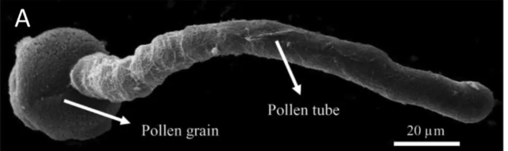
As it is shown on Figure 5, the arrangement of endomembrane, mitochondria, vesicles, and other organelles seem to follow the cytoplasmic streaming pattern that, in angiosperm pollen is organized in the shape of an inverse fountain (Mascarenhas, 1993; Malho, 2006).
Figure 5. Cellular structure of the pollen tube. A) Scanning electron micrograph of Camellia japonica pollen tube germinated in vitro. Scale bar = 20 µm). B) Schematic representation of the pollen tube cytoarchitecture and polar cellular structure; apical cell wall of the pollen tube contains pectin polymers (methylesterified pectin) and the shank is composed of two or three cell wall layers comprising mainly callose, cellulose and de-esterified pectins (Aouar et al., 2010). When pectin methyl esterase is secreted at the apex of the tube via vesicle exocytosis, methylesterified pectin becomes de-esterified (Geitmann and Steer, 2006). Orange arrows represent cytoplasmic streaming parallel to the longitudinal axis, forward movement in the cortex and rearward in the centre of pollen tube. The red arrows represent vesicle trafficking and movement of secretory vesicles (green spheres) accumulating in the apical region shows the exocytosis process and endocytosis (yellow vesicles) taking place at the base of apex. The white arrow represents growth direction of pollen tube to the axis length in normal cells. Objects are not drawn to scale.
3. Sexual plant reproduction
On the way to the female gametophyte, the male gametophyte enters into contact with numerous tissues of the sporophyte (Figure 1). The pollen grain adheres to the stigmatic papilla. During elongation the tube comes into contact with the stylar transmitting tissue and the placenta cells of the ovary (Geitmann and Palanivelu, 2007; Lord and Russell, 2002; Cheung and Wu, 2001; Esau, 1977). Because of the complexity of the path through which the pollen tube has to grow, it needs to follow the guidance cues provided by the pistillar tissues and the female gametophyte. These cues are both of mechanical and chemical nature. The ability of the pollen tube to turn in response to chemical triggers emitted by the female gametophyte has been demonstrated using the in-vitro system of Torenia (Higashiyama and Hamamura, 2008). In vitro growing pollen tubes were exposed to isolated ovules and even when these were relocated, the tubes followed. The precise target area for tubes grown in this setup was the micropylar end of the protruding embryo sac (Yetisen et al., 2011; Higashiyama and Hamamura, 2008; Geitmann and Palanivelu, 2007; Palanivelu and Preuss, 2000; Hülskamp et al., 1995). These in vitro experiments are relevant, since in vivo, the tube repeatedly has to change its growth direction to find its target. Pollen tube growth is therefore an effective model system to study tropic growth behaviour at the cellular level. Numerous studies have attempted to identify the nature of the signalling agents emitted by the pistil and female gametophyte, such as sterols and lipids (Major et al., 2009; Chantha et al., 2007; Germain et al., 2006). Recently peptides, azadecalin-like molecules produced by Arabidopsis pistils that promote rapid fertilization by suitable pollen and germination (Qin et al., 2011), but the behaviour of the pollen tube proper upon perception of these signals is poorly characterized.
The pollen tube elongates inside the pistil at rates that vary between micrometers/hour to centimeters/hour. The in-vitro growth of pollen tubes from commonly used species shows
different growth rate in Arabidopsis (13.20 µm/h) (Gebert et al., 2008), Camellia (1-2 mm/h) (data from our lab), Nicotiana tabacum (1.7 mm/h) (Sanchez et al., 2004), Colchicum autumnale (2.75 cm/h) and maize (1 cm/h), (Sanati Nezhad et al., 2013a and d; Taylor and Hepler, 1997). In Lilium longiflorum, the growth rate varies between 2 mm/h (in vivo) (van der Woude and Morré, 1968) and 0.5 mm/h (in vitro) (Bou Daher et al. 2011). The range of growth rates of taxa in ancient angiosperms (Amborella, Nuphar, and Austrobaileya) is 80 to 600 µm/h. The growth rate of pollen tube in gymnosperms is generally <20 µm/h. The calculated maximum growth rates for gymnosperms in vivo are ≈1µm/h in Zamia (Cycadales), 2 µm/h in Ginkgo (Ginkgoales), 5 µm/h in Gnetum (Gnetales), and 6 µm/h in Agathis (Coniferales). In vitro growth rates of other various gymnosperms, however, are in the same range of <1 µm/h in Pinus to 10–20 µm/h in various other gymnosperms (Williams, 2008).
The cellular mass of transmitting tissue represents the pathway for pollen tube, after the pollen grain lands on the stigma and germinates. After penetration inside the transmitting tissue, the tube reaches the ovary and passes to the internal surface of placenta (Erbar, 2003). The signals emitted from the female gametophyte guide the pollen tube toward the funiculus, where the ovule attaches to the placenta. Then the pollen tube targets the micropyle, the aperture of the shell that covers the ovule. The pollen tube then has to pass another gate in order to reach the female gametes. Invading the micropyle allows the pollen tube to cross the tissue layer called nucelleus that covers the female gametophyte. After invading, the pollen tube will meet the synergid cells adjacent to the egg cell. When the tube penetrates the filiform apparatus of one synergid, it bursts to release two sperm cells. One fertilizes the egg cell to generate a zygote that will develop into the embryo, and the other combines with the central cell to give rise to the endosperm that is responsible for nourishing the embryo (Taylor and Hepler, 1997).
4. Invasive growth
Tip-growing cells typically have to invade and penetrate the surrounding area to reach their destination. Root hairs extend through the soil to uptake water and mineral nutrients to feed the plant. Fungal hyphae either absorb the nutrients from a biotic host or penetrate abiotic substrate in search for nutrients and water (Takemot et al., 2006; Harris, 2008; Haling et al., 2013). In our model system, the pollen tube is challenged by different cell structures from the dry or glandular stigma toward the stylar transmitting tissue and the placenta tissue of the ovary and finally the surface of the funiculus and ovule (Cheung and Wu, 2001; Esau, 1977) (Figure 3 and 4). The pollen tube therefore encounters a series of mechanical obstacles while it attempts to reach its target and accomplish its tasks.
The type of style that pollen tube passes through to reach the ovary could be either hollow or solid depending on the species. In the case of solid style pollen tube needs to invade the apoplast of the transmitting tissue. The transmitting tissue contains an intercellular matrix containing ingredients required for pollen tube growth such as sugars, glycoproteins, and amino acids (Cheung and Wu, 2001; Lord, 2003; Geitmann and Palanivelu, 2007). During the passage of the pollen tube via the transmitting tissue matrix, it has to push and overcome the mechanical obstacle represented by the apoplast. The secretion of digestive enzymes such as hydrolytic enzymes, glycosidases, and the wall loosening protein expansin, by the pollen tube can assist its penetration (Graaf and Derksen, 2001; Cosgrove, 2000).
To transfer the sperm cells safely to the ovary, especially in the case of a solid style, the pollen tube has to withstand the lateral pressure exerted by the transmitting tissue and keep its tubular shape to enable the sperm cells to continue moving forward within the tube. The ability to invade a matrix and avoid collapse makes tip-growing cells interesting objects to study invasive growth. Understanding the mechanical aspects of invasion helps us to understand the biological principles governing the functioning of these cells.
From earlier experiments we know that the pollen tube's ability to penetrate a stiffened matrix is affected upon pharmacological manipulation of the cytoskeleton (Gossot and Geitmann, 2007). However, this test was done using agarose, the mechanical properties of which are not calibrated. Here we wanted to use an in vitro system that imitates the in vivo conditions better and in more calibrated manner of mechanical forces.
Measuring the invasive force of the pollen tube is technically challenging. The invasive force of fungal hyphae, however, was measured using a miniature strain gauge (Money, 2004), but the huge size of cantilever (100µm thickness and 10 mm width compared to the size of the cell 10µm) was its greatest disadvantage as imaging is challenging. In a different approach the invasive force of infection hyphae was measured using a synthetic membrane as a waveguide (Bechinger et al., 1999). However, this requires the adhesion of an appressorium to the membrane and can thus not be used for pollen tubes. To measure the forces exerted by growing pollen tubes we developed an experimental set-up using Lab-On-Chip (LOC) technology.
5. Objectives
The principal goal of my project is to characterize the mechanisms that enable the pollen tube to navigate the mechanical obstacles presented by the pistillar tissues and to respond to directional triggers. The following are the detailed objectives:
1. Developing the Lab-On-Chip platform to study the mechanical aspects of individual pollen tubes.
2. Studying the invasive growth of pollen tubes using the Lab-on-Chip platform 2.1. Quantifying the dilating force of pollen tubes to invade narrow spaces 2.2. Studying the ability of pollen tubes to navigate mechanical obstacles
3. Assessing the suitability of the Lab-On-Chip platform for high-resolution and fluorescence microscopy.
Chapter 1. Development of the microfluidic platform
TipChip
This chapter explains our collaboration with the laboratory of Professor Packirisamy at the Mechanical and Industrial Engineering Department, Concordia University. Three graduate students (A. Sanati Nezhad, M. Ghanbari, and C. Agudelo) of the Packirisamy lab fabricated the TipChip devices using soft lithography techniques. I performed experimental tests in collaboration with the Packirisamy lab members. The data were published in four papers (Agudelo et al., 2012, 2013a and b; Sanati Nezhad et al, 2013a, b and d). The present chapter focuses on the aspects in which I was directly involved. I contributed Figures 7i, 8c, 8d in this chapter while the other figures were prepared by the co-authors.
Summary
Studying the mechanical aspects of plant tip-growing cells in-vitro is challenging since the size of the measuring device needs to be in the same dimension as that of the cell. To be able to simulate the growth conditions that a pollen tube encounters in the in vivo situation, in collaboration with the laboratory of Dr. Packirisamy, Concordia University, we developed a series of microchips that mimic mechanical obstacles and serve to measure the biomechanical properties of growing pollen tubes. We developed TipChip microfluidic devices system based on Lab-On-Chip technology. These microfluidic devices are made from PDMS (polydimethylesiloxane) with soft-lithography. Our developed TipChip micro devices allowed us to study the growth behaviour and mechanical features of pollen tubes. To ensure reproducible growth conditions we studied the effects of varying the growth medium flow rate, the depth and the width of microchannels on the growth velocity of pollen tubes. Through our collaboration, the LOC devices considering the basic design of channels were fabricated and
tested for fluid flow rate. I contributed to several of the experimental assays and I tested the compatibility of LOC devices with fluorescence microcopy.
1.1. Introduction
The walled cells of plants have a stiff extracellular matrix outside of the plasma membrane that influences growth, division and differentiation of the cells. The polarized growth of certain walled cells is therefore an interesting phenomenon, since in addition to growing in size, the cell actually exerts forces against the surrounding substrate. Well investigated tip-growing cells include root hairs, fungal hyphae and pollen tubes (Money, 2004; Brand and Gow, 2008; Palanivelu and Johnson, 2011; Winship et al., 2011).
Growth and morphogenesis of walled cells are a result of cellular expansion involving the deformation of the cell wall driven by water uptake. In pollen tubes, the cellular expansion occurs at the very end of the cell and at the same location new cell wall material is assembled resulting in a cylindrical protuberance with oval or hemispherical shaped apex. The delivery of new cell wall material and the turgor pressure applying stress on the cell wall are necessary to generate the actual growth process (Rojas et al., 2011; Geitmann and Ortega, 2009; Geitmann and Dumais, 2009; Geitmann and Steer, 2006; Harold et al., 1995).
Besides growing rapidly (up to 1 cm/h in pollen tubes and fungal hyphae), tip growing cells are able to control the direction of growth, a skill that they share for example with neurons (Palanivelu and Preuss, 2000). To answer many of the open questions regarding these cell types, we need to develop methods that enable us to carry out more complex experiments, as well as large-scale phenotyping. Here I describe the microfluidic platform developed in collaboration with our colleagues at Concordia University with the aim to investigate single tip growing cells in highly reproducible manner. This TipChip platform has been tested and optimized for pollen, but it could easily be used for other tip-growing cells such as hyphae (fungal) and moss
protonemata (moss spores).
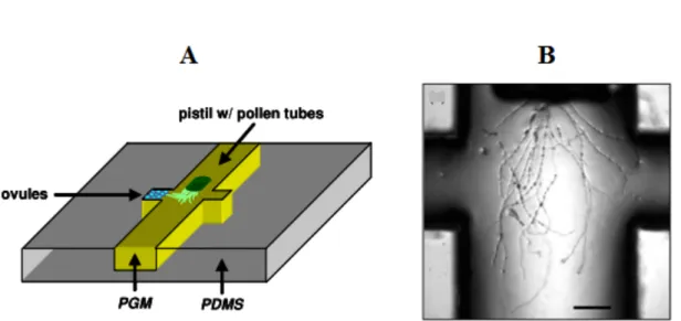
Since the pollen grains are easy to collect, store, and germinate, we chose the pollen tube as a model system to optimize our technology of Lab-On-Chip (LOC) and study the mechanical behaviour of tip-growing cells. This technology allows the construction of miniature devices that can be designed to simulate certain properties of the tissues through which pollen tubes have to grow in the plant. Yetisen et al (2011) were the first to use such a micro-device in order to analyze the behaviour of pollen tube in response to isolated ovules. However, their micro-device design is very simple, consisting of a main central groove and side chambers in one of which the ovules were placed (Figure 6) and the dimensions of the structures are orders of magnitudes bigger than the cells.
Figure 6. Micro-device for growing pollen tube. (A) Schematic of micro-device showing the overall setup of the system. (B) Close-up of grown pollen tubes inside the system. Provided by Yetisen et al., (2011). Scale bar =200µm.
Malho, 2006; Cheung and Wu, 2007, 2008; Geitmann and Palanivelu, 2007; Brand and Gow, 2008; Palanivelu and Tsukamoto, 2011; Qin and Yang, 2011). In the past, pollen tube performance has typically been assessed based on quantification of seed set (in vivo), quantification of germination percentage (in vitro), average growth rate (in vivo and in vitro), and on cell morphology (in vitro). While these approaches provide excellent quantitative information using bulk samples (e.g. Bou Daher et al. 2008) more detailed information can be gained from more specific approaches. Among these are the vibrating probe, a technique that allows monitoring ion fluxes (Feijò et al., 1995; Messerli and Robinson, 1997, 1998, 2003), a microindenter to measure the biomechanical properties of pollen tubes (Geitmann et al., 2004; Parre and Geitmann, 2005a,b; Zerzour et al., 2009), and microstructured obstacles and directional triggers to investigate invasive and tropic growth (Malhò et al., 1992; Palanivelu and Preuss, 2000; Lord, 2003; Gossot and Geitmann, 2007; Higashiyama and Hamamura, 2008; Amien et al., 2010; Bou Daher and Geitmann, 2011; Palanivelu and Tsukamoto, 2011).
A miniature strain gauge has successfully been used to measure the invasive force of fungal hyphae (Money, 2004). The size of the silicon beam used (a cantilever of 100 µm thickness and 10 mm width) compared to the size of the cell (10 µm) is the disadvantage of this method as it renders precise imaging of the process difficult and the silicon beam is not soft enough to sense the cellular force with sufficient precision. In addition, the parameters such as the shape of cell, growth inhibition, or a shift in growth direction cause the data to be rather variable. Money (2004) also measured the hyphal force using an indentation technique based on a synthetic membrane used as a `waveguide` (Bechinger et al., 1999). This method requires the fungal appressorium to adhere to the membrane. Germlings of pathogens typically secrete an adhesive along the elongating germ hypha that allows them to attach to the surface (Money (2004). In vivo grown pollen tube of lily are also known to produce clusters of F-actin as a sort of internal structure that might connect to external attachments (Pierson et al, 1986), when the tube passes
through the pistil from stigma to ovary. However, this configuration and adhesion was not detected in vitro (Park et al., 2000). Pollen grains or tubes do not adhere to artifical membranes and hence this method would not work.
These techniques, although useful, are time-consuming, since only one cell can be tested at a time and results are highly variable. Our newly designed platform allows us to examine several tip-growing cells at the same time, and in highly reproducible manner. Since the platform's design is flexible, it makes an ideal system for both phenotyping and developing new experimental methodologies for the investigation of tip-growing cells.
The TipChip platform is based on microelectromechanical systems (MEMS) technology. This technology has been exploited in biological and medical applications to simplify sophisticated functions such as chemical reactions, drug development and bioassays by integrating them within a single micro-device, called a Lab-on-a-Chip (LOC; Cheung and Renaud, 2006; Giouroudi et al., 2008; Nuxoll and Siegel, 2009).
In this chapter I briefly describe the geometry and fluid flow conditions of the LOC as developed and optimized by our collaborators in the Packirisamy lab (A. Sanati Nezhad, M. Ghanbari, and C. Agudelo). The versatility of the device is illustrated by several experimental assays. This work has been published (Sanati Nezhad, et al., 2013a, b, c and d, and Agudelo, et al., 2013, 2014). I was involved in testing most of these devices and I performed my experiments using bright field and confocal laser scanning microscopy (Figures, 7i, 8c, and d,).
1.1.1. Microfluidic devices imitating in-vivo conditions
In nature, the pollen grain on the stigma germinates after hydration and then the pollen tube grows through the stylar tissue to reach to the ovary (Lord and Russell, 2002). On this path, the pollen tube faces different structures from the dry or glandular stigma, the stylar transmitting tissue, the placenta tissue of the ovary and finally the surface of the funiculus and ovule (Cheung and Wu, 2001; Esau, 1977) (Figure 3). The ability to invade the apoplast of the transmitting tissue is a requirement for successful pollen tube growth, since the appoplast acts as a mechanical obstacle for passing pollen tube. Furthermore, the tube has to resist any lateral pressure exerted by the transmitting tissue to keep its tubular shape and permit the passage of the sperm cells. The purpose of the microfluidic device was to mimic this situation in the transmitting tissue in order to understand the mechanism that allows the pollen tube to exert its delivery function against the impedance of the pistillar structures. We achieved this by a variety of design features. An overview of the designs and fabrication methods is represented in section 1.3. Agudelo et al. (2012) described in detail the fabrication of the LOC devices.
1.1.2. Design and Fabrication
The TipChips were fabricated using soft lithography technique (Agudelo et al., 2012). This entails the production of a photomask that is used to project a pattern onto the photoresist. Tests done by Agudelo et al (2013) for photomask production methods (digital printing at 3600 dpi and direct writing laser (DWL) lithography), revealed that using the DWL lithography technique the surface of microchannels are smoother. This more precise technique is expensive, but is necessary to ensure that the microstructured features have a resolution that is precise enough for the dimensions of pollen tube (see Figure 8 for examples of both techniques).
mold and the microfluidic designs are adapted to meet the criteria of individual experimental approaches. The PDMS at the entrance and exits of the microfluidic network was punched to make an inlet and outlets. The final fabricated microfluidic network of PDMS was sealed by a cover slip (Squares No. 2; Thickness: 0.17 to 0.25mm; Size: 25mm, http://www.fishersci.com; Harrick Plasma PDC-001, http://www.harrickplasma.com) to make the devices compatible for microscopy using high numerical aperture objectives. Plastic tubes were inserted at the inlet and outlets. The pollen grain suspension and growth medium was injected into the device via the inlet, and the circulation through the microfluidic network and
Figure 7. Basic design of the multichannel TipChip platform.
(a) Image of the TipChip showing the PDMS layer attached to a cover slip, with inlet and outlets. (b) Design of the microfluidic network in the TipChip. The pollen suspension is injected via the inlet; laminar flow moves the pollen grains through the distribution chamber, where the grains are trapped at the entrances of the microchannels. Excess fluid and pollen grains are evacuated through the distribution chamber outlet. (c) Rectangular portion of distribution chamber of the TipChip as shown in (b), illustrating various types of microchannel geometries. Scale bar = 500 µm (dark gray in lower left corner). (d) Alternative design with central barrier. (e) Fluid flow streamlines within the distribution chamber. (f) Detail of image (e) providing the simulated streamlines detail (red) with the movement of experimentally observed pollen grain (blue) through the distribution chamber. (g) Micrographs of trapping a pollen grain at the microchannel entrance. A single pollen grain is shown at three different times as it is driven by fluid flow indicated by the arrow. Scale bar = 100µm. (h) Scanning electron micrograph of a trap entrance. Scale bar = 100 µm, from Agudelo et al., (2013); (i) Pollen tube growing in an LOC and labeled with FM1-43 to reveal vesicles is shown in fluorescent mode (left), in brightfield mode (middle) and in an overlay of both (right). Scale bar = 20 µm.
the exit of the growth medium was controlled at the outlets.
For simultaneous observation of multiple cells, the set-up needed to contain multiple microchannels. Ungerminated pollen grains in growth medium solution are injected and only upon placement the pollen grains germinate to form the tubes. Using laminar fluid flow, the pollen grains are guided toward the microchannel entrances where they are trapped. The main platform of microfluidic network contains an inlet, a distribution chamber with access to eight microchannel entrances, and two different kinds of outlets - one for the evacuation of excess pollen grains from the chamber and others to drain liquid from the ends of the microchannels to allow a continuous flow of liquid. The enclosed microchannels prevent evaporation of the growth medium surrounding the cells. Evaporation is a technical problem in open microchannel systems (Yetisen et al. 2011).
The height of the distribution chamber was normally between 1.2 and 1.5 times the pollen grain diameter to avoid the accumulation of the grains inside the chamber, which would create a mechanical barrier for the fluid as well as preventing microscopical observation. The pollen grain of the species used in this study, Camellia japonica, is 60 µm wide. Therefore, the height of the microfluidic network was set to 80 µm. The width of pollen tube of this species is 14 to 20 µm and it has a very fast and straight growth. These characteristics of Camellia japonica make it a perfect model system for cytomechanical research as established previously (Bou Daher and Geitmann, 2011). However, while the current version of the TipChip is optimized for Camellia, it can easily be adapted for the use with either pollen from other species or fungal spores.
The design of the microfluidic network had to provide for the particular challenges associated with our cellular system. We wanted to trap pollen grains and immobilize them in the presence of continuous fluid flow and the emerging pollen tubes were supposed to grow into narrow microchannels in which experimental design features could be incorporated. Earlier
devices (Tan and Takeuchi, 2007; Kobel et al. 2010) trap a relatively small number of particles in short microchannels. In contrast we wanted to trap individual pollen grains at one end of long channels, and to observe many growing pollen tubes in the device. Also, we wanted to ensure that only one or few pollen grains would be trapped at each microchannel entrance, since accumulations of pollen grains would build a mechanical barrier for the circulation of fluid flow potentially affecting the experimental conditions and the reproducibility of the experiments.
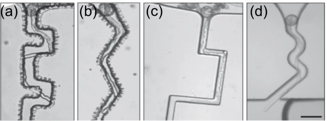
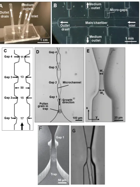
Two different geometries were tested for the distribution chamber (Agudelo et al., 2013): a simple rectangular shape (Figure 7b, c) and an oval shape containing a central barrier (Figure 7d). Pollen grains were trapped at entrances through transportation of laminar fluid flow created by slow injection of pollen suspension (Sanati Nezhad et al., 2013d). To trap the grains at the entrance, the end of the mirochannel was designed as a curved notch, smaller than the size of pollen grains (30 µm). The pollen tubes are then guided through the narrow canals of the microchannels. Depending on the desired experimental conditions, the microchannels could be equipped with mechanical obstacles, chemical gradients, electric fields, and biosensors (Figure 7c) (Agudelo et al., 2013).
Figure 8. Microchannel fabrication using two high-resolution methods. (a, b) The fabrication of microchannels provided by a transparency film photomask, which is taken by high-resolution digital printing (3600 dpi). (c, d) Microchannels is fabricated using a high-resolution glass mask created by direct-write lithography. The smooth surface of PDMS in (c) and (d) is the reason for choosing this higher-resolution technique in the microchannel fabrication. Scale bars = 100 lm. Image is from Agudelo et al (2013).
1.2. Design and fabrication of LOC platform
The design of the channels has to take into consideration the size of the pollen grain and the pollen tubes of the species to be used. The selected species for this study is Camellia japonica. The pollen grains germinate very quickly (20 to 30 minutes after imbibition) and the tubes grow very fast (0.2 µm/sec) thus minimizing experiment timeAlso, compared to other species (such as Arabidopsis), the tubes have a large diameter (approximately 18 µm), making Camellia an excellent model species to study the mechanical properties of the pollen tube. This species will be used for those portions of the project that pertain to cell mechanics.
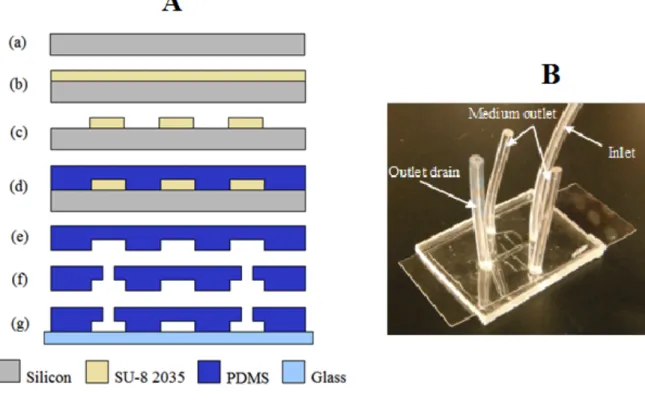
Figure 9. LOC fabrication. (A) (a) Schematic representation of a LOC: Silicon wafer standard clean, (b) SU-8 2035 Photoresist spin coating, (c) Lithographic patterning and photoresist development, (d) PDMS pouring and curing, (e) PDMS pouring and curing, (f) Fluidic access punching, (g) PDMS-glass bonding. (B) Fabricated LOC on a cover slip. Image is from Agudelo et al. (2014)
The fabrication of the LOC is explained in detail by Agudelo et al. (2014). Briefly, the LOC was designed using computer-aided design (CAD) and the design was transferred to a transparent film using digital printing or to glass using DWL lithography. To make a mold for the LOC, a silicon wafer was coated with the negative photoresist S8 to the desired thickness (usually 80 µM), covered with the film or glass pattern and exposed to UV light, and developed. A mixture of PDMS base and curing agent were poured on the resulting mold. After curing, the PDMS was removed from the mold and inlet and outlets were punched. A glass coverslip was then bonded to the device.
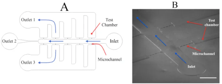
Figure 10. Presentation of LOC. (A) Schematic illustration of basic design for microchannels (LOC). (B) Scanning electron microscopy of LOC for narrow spaces. Pollen grains and medium are injected through the inlet tube. Untrapped pollen grains exit via outlet 2 and growth medium flowing through channels exits via outlets 1 and 3. Scale bar for (B) is 1mm.
The general design of the microfluidic network of the TipChip is explained in detail in Agudelo et al (2013, 2014) and Sanati Nezhad et al (2013a, b and d). The microfluidic network comprises a distribution chamber for injected pollen grains, and microchannels along which pollen tubes grow (Figure 8, provided by Agudelo et al, 2013). To ensure normal grain germination any mechanical obstacles are placed a minimum of 100 µm from the microchannel entrance.
Chapter 2: Invasive force
Amir Sanati Nezhad and I did the experimental work for this chapter and our data were published in PNAS (2013a), Royal Society of Chemistry (2013), and Biomedical Microdevices (2013). All the tests and experiments relating to the mechanical behaviour of pollen tubes during passage through narrow gaps were done in our laboratory at IRBV, The images were analyzed using ImageJ software in order to measure the changes in diameter of the pollen tube. Amir Sanati Nezhad did the chip design, most calculations and the modeling.
Summary
The growth of the pollen tubes inside the stylar transmitting tissue of the pistil has been studied from the point of view of the guidance signals emitted from the sporophytic pistillar tissues and female gametophyte (Yetisen et al., 2011; Higashiyama and Hamamura, 2008). Since the pollen tube meets different types of cells, from dry stigma to the stylar transmitting tissue, it has to invade and penetrate inside the apoplast of all these cells to finally reach the surface of ovule (Lord and Russell, 2002; Cheung and Wu, 2001; Esau, 1977). The mechanical behaviour of pollen tubes during growth is not well understood. To determine the invasion force of the pollen tube, we used the novel technology of lab-on-chip (LOC) as in vitro condition to mimic the in vivo situation. In this study our model system is the pollen tube of Camellia japonica. Our results showed changes in growth velocity, when pollen tubes passed through narrow spaces during penetration. Also during invasion, the time necessary to pass the obstacle increased with decreasing the available space.