HAL Id: hal-00751755
https://hal.inria.fr/hal-00751755
Submitted on 14 Nov 2012
HAL is a multi-disciplinary open access
archive for the deposit and dissemination of
sci-entific research documents, whether they are
pub-lished or not. The documents may come from
teaching and research institutions in France or
abroad, or from public or private research centers.
L’archive ouverte pluridisciplinaire HAL, est
destinée au dépôt et à la diffusion de documents
scientifiques de niveau recherche, publiés ou non,
émanant des établissements d’enseignement et de
recherche français ou étrangers, des laboratoires
publics ou privés.
Target tracking in 3D ultrasound volumes by direct
visual servoing
Caroline Nadeau, Hongliang Hen, Alexandre Krupa, Pierrre Dupont
To cite this version:
Caroline Nadeau, Hongliang Hen, Alexandre Krupa, Pierrre Dupont. Target tracking in 3D ultrasound
volumes by direct visual servoing. Hamlyn Symposium on Medical robotics, Jul 2012, London, United
Kingdom. �hal-00751755�
Target Tracking in 3D Ultrasound Volumes
by Direct Visual Servoing
Caroline Nadeau
1, Hongliang Ren
2,3, Alexandre Krupa
1, and Pierre Dupont
21
Inria Rennes-Bretagne Atlantique, France, IRISA, (Caroline.Nadeau,Alexandre.Krupa)@inria.fr.
2
Children’s Hospital Boston and Harvard Medical School, Boston, MA, USA
2(hongliang.ren, pierre.dupont)@childrens.harvard.edu.
3
Department of Bioengineering, National University of Singapore, Singapore
INTRODUCTION
Three dimensional ultrasound (3DUS) guided robotic beating heart surgery is an emerging computer-assisted surgical technique. Motion tracking of both the robot and the heart tissue is one of the key open problems in these procedures and the use of 3DUS imaging offers the possibility to extract, intra-operatively and in real time, the motion of one or more targets.
In this paper, we present a visual servoing approach to track the motion of a single target that can consist of either the surgical robot or cardiac tissues. To deal with the low quality of the 3DUS volumes, the proposed intensity-based approach requires no primitive extraction or image segmentation. This approach does not involve time consuming processing steps and can be applied to a wide range of tissue types and medical instruments.
Unlike previous work [1] where the motion compen-sation task was realized physically by moving the probe attached to a robotic arm to compensate for abdominal organ motion, we propose here to track the motion of the target using a 3D region of interest (ROI) which is automatically moved within the 3D US volume to compensate for both target and probe motion. This is a new method compared with conventional 3DUS-based target motion tracking or imageless motion tracking as surveyed in [4]. In-vivo animal experiments were conducted to validate the tracking approach.
MATERIALS AND METHODS
3DUS guided robotic beating heart surgical procedure
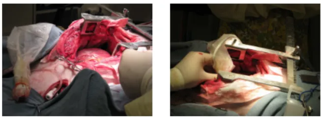
Image volume sequences were acquired during an in-vivo porcine robotic surgery using a concentric tube robot [3]. The 3D image acquisition system was a Philips IE33 system manufactured by Philips Medical (www.philips.com). The robot was inserted through a small incision in the jugular vein on the neck and then steered inside the right atrium. The surgeon positioned the matrix-array 3D probe epicardially on the heart to image the robotic instrument tip and the intracardiac tissue (Fig. 1). The system was used to acquire US volumes at a frame rate of 25 Hz for durations of 10 sec. These volumes were then loaded in a rendering software
we have developed and the tracking was performed off line. Standard settings of the imaging parameters were used during image generation, including 50% overall gain, 50% compression rate, high density scan line spacing, 6 cm image depth, and zero dB power level.
Fig. 1. Beating-heart intracardiac surgery with 3DUS probe manually positioned on the epicardial surface.
Intensity-based visual servoing
In this procedure, the US probe is not actuated and motion tracking is performed in the acquired US vol-ume by moving a ROI to compensate for probe and target motion. An image-based visual servoing strategy is considered for minimizing the error e(t) = s(t) − s∗ between a current set of visual features s and a desired one s∗ by applying an instantaneous velocity vc to
the ROI. To observe an exponential decrease of this visual error, the classical control law [2] is given by: vc= −λ cLs
+
(s(t) − s∗), where λ is the gain involved in the exponential decrease of the error and cLs
+
is the pseudo-inverse of an estimation of the interaction matrix Ls that relates the variation of the visual features to the
velocity vc.
To deal with the low quality of the 3D US images, we consider as visual features s the intensity values of the voxels of the 3D ROI:
s= {I1,1,1, ...,Iu,v,w, ...,IL,M,N},
where L, M and N are respectively the width, the height and the depth of the ROI and where Iu,v,wrepresents the
intensity of the voxel of 3D coordinates(u,v,w) in the US volume. The interaction matrix associated to these intensity features has been modeled in [1] and depends only on the 3D image gradient and the coordinates of the voxels in the US volume.
RESULTS
We conducted experiments to evaluate the ability of the algorithm to track cardiac tissue and to track the robot. The results of the soft tissue tracking task are displayed in Fig. 2. In the first volume provided by the 3D probe, the central image of the volume is displayed to allow the user to delineate the desired anatomic structure by a bounding box used as a basis for the 3D ROI considered in the control law. Then, during the subse-quent volumes, the velocity computed by visual servoing is applied to this ROI. Compensated tissue motion is due predominantly to the cardiac cycle. To validate visually the tracking task, we display during the cardiac motion the interpolated US image going through the center of this ROI, first without compensation (c), then with compensation (e). In both cases, the corresponding difference images (d,f) with the desired US view are also computed. The efficiency of the compensation is shown on the difference image (f) where the ROI is roughly gray with no strong gradient, compared to the difference image (d). Moreover a visual error is defined as the Euclidean norm of the visual vector and is displayed on the curve (b). (a) (b) 0 1000 2000 3000 4000 5000 0 50 100 150 200 250 iteration Visual error Cardiac motion Compensation (c) : No compensation (d) : No compensation
(e) : With compensation (f) : With compensation
Fig. 2. Tracking results for cardiac tissue. The desired anatomic
target is delineated on the central view of the initial US volume (a). The motion compensation is validated by the decrease in visual error (b) and by the difference images (d,f) corresponding to the central image extracted from the ROI at iteration 240, respectively without (c) and with (e) compensation.
Experiments were also performed to evaluate intensity-based visual servoing for tracking robot motion during surgery. In this case, we defined the desired ROI to include the tip of the concentric tube robot, as it was navigated inside the right atrium of the beating porcine heart [3]. Robot tip motion is automatically tracked by the proposed intensity approach during its movement. The results are presented in Fig. 3. In each of the acquired 3DUS volumes, the ROI remains centered on
the tool tip, which validates the tracking task. Fig. 3(e) shows the decrease of the visual error with the tracking and Fig. 3(f) gives an estimate of the tool motion. This motion corresponds to a forward and backward translation along the direction of the tool shaft.
(a) : vol. 0 (b) : vol. 70
(c) : vol. 140 (d) : vol. 250 (e) 0 1000 2000 3000 4000 5000 6000 7000 8000 0 50 100 150 200 250 iteration Visual error Cardiac motion Compensation (f) -1 -0.8 -0.6 -0.4 -0.2 0 0.2 0.4 0.6 0.8 0 50 100 150 200 250 iteration
Probe pose error (mm, deg) tx ty tz rx ry rz
Fig. 3. Tracking results for the robot. The robot tip indicated by
the surgeon in the initial US volume (a) is tracked in the successive ones (b,c,d). The tracking task allows the reduction of the visual error (e) and the estimation of the tool pose (f) (the θ u representation is considered to describe the orientation, where u= (uxuyuz)⊤is a unit vector representing the rotation axis and θ is the rotation angle.)
DISCUSSION
We have presented a new direct visual servoing method for the estimation and compensation of rigid motions using 3DUS volume sequences and illustrated its effectiveness using data from robotic beating-heart surgery. These experiments validated the approach both for tracking the rigid motion of robotic tools and also for tracking the quasi-rigid motion of heart tissue.
As a next step, we will investigate extending the method to deal with the non-rigid motions of heart tissue using a deformable grid instead of the rigid ROI.
Acknowledgment: This work was supported by the National Institutes of Health under grants R01HL073647 and R01HL087797 and by the ANR project US-Comp of the French National Research Agency.
REFERENCES
[1] C. Nadeau, A. Krupa, Intensity-based direct visual servoing of an ultrasound probe. IEEE Int. Conf. on Robotics and Automation,
ICRA’11, Shanghai, China, May 2011.
[2] B. Espiau, F. Chaumette and P. Rives, A new approach to visual servoing in robotics. IEEE Trans. on Robotics, vol. 8(3): 313-326, 1992.
[3] Gosline A, Vasilyev N, Butler E, Folk C, Cohen A, Chen R, Lang N, del Nido P, Dupont P. Percutaneous Intracardiac Beating-heart Surgery using Metal MEMS Tissue Approximation Tools. Int J
Robotics Research 2012; in press.
[4] H. Ren, N. V. Vasilyev, and P. E. Dupont, Detection of curved robots using 3d ultrasound, IEEE/RSJ International Conference