Science Arts & Métiers (SAM)
is an open access repository that collects the work of Arts et Métiers Institute of
Technology researchers and makes it freely available over the web where possible.
This is an author-deposited version published in: https://sam.ensam.eu Handle ID: .http://hdl.handle.net/10985/8360
To cite this version :
Corinne NOUVEAU, Chafik LABIDI, Jean-Pierre FERREIRA-MARTIN, Robert COLLET, Mohamed Abdou DJOUADI - Application of CrAlN coatings on carbide substrates in routing of MDF - Wear - Vol. 263, p.1291-1299 - 2007
Any correspondence concerning this service should be sent to the repository Administrator : [email protected]
Application of CrAlN coatings on carbide substrates
in routing of MDF
C. Nouveau
a,∗, C. Labidi
a, J.-P. Ferreira Martin
b, R. Collet
a, A. Djouadi
c aLaBoMaP, ENSAM, Rue Porte de Paris, F-71250 Cluny, FrancebISOROY, Paris, France
cInstitut des Mat´eriaux Jean Rouxel, UMR 6502, 2 rue de la Houssini`ere, B.P. 32229, F-44322 Nantes Cedex 3, France
Abstract
This study deals with the development of Chromium Aluminium Nitride (CrAlN) hard coatings (by varying the nitrogen content in the plasma, the target bias voltage, the working pressure and the deposition time) and their characterization by physical and mechanical techniques (XRD, nanoindentation, Young’s modulus, stress, scratch-test, composition, etc.) in order to determine the optimal deposition conditions to apply the coatings to carbide substrates.
Moreover, in order to improve the adhesion of the same optimal hard coatings and as it was efficient with Diamond Like Carbon (DLC) coatings, we tried to modify the carbide inserts by chemical attacks with Murakami’s agent before machining.
The coated tools (with and without Murakami’s attack) were then tested in routing of Medium Density Fibreboard (MDF). A comparison of the abrasion and shock resistance of the conventional tools with the treated ones, was made. The efficiency of Murakami’s agent was also studied. It was obvious that the coated carbide tools had greater tool life than the untreated ones. Besides, Murakami’s attack was not optimized or not a solution to improve the adhesion of nitride coatings on carbide inserts.
Keywords: CrAlN; Magnetron sputtering; Routing; MDF; Murakami; Abrasion and shock resistance
1. Introduction
Nowadays, hard coatings are commonly used to increase the wear resistance of cutting tools in metal machining[1]. In wood machining, the application of coatings as wear or corrosion pro-tection of cutting knives is not common, though previous works
[2,3]have shown their potential in peeling and routing. Even if the coatings caused an increase in the service life of the cut-ting tools, their adhesion was not sufficient especially on carbide inserts. This could limit their use. Nevertheless, the solution to increase the adhesion of hard coatings such as CrAlN on car-bide substrates could be a surface preparing by the Murakami’s agent which showed an improvement of the adhesion of
Dia-mond Like Carbon coatings in other studies [4]. The aim of
this work was first to develop CrAlN layers with optimal phys-ical and mechanphys-ical properties to apply them to carbide inserts.
∗Corresponding author. Tel.: +33 3 85 59 53 35; fax: +33 3 85 59 53 70.
E-mail address:[email protected](C. Nouveau).
The coatings were then tested by routing MDF with carbides previously attacked or not with Murakami’s agent.
2. Experimental details
2.1. Treatments and characterizations
The deposition of the CrAlN coatings was carried out by a dual RF magnetron sputtering system (NORDIKO type 3500–1356 MHz). A pure sintered CrAl target was used (25% at of Al in weight). We studied the variation of parameters such as the nitrogen content in the plasma (10, 17.5, 25, 35,
50 and 100%), the working pressure (2, 4, 8 and 12bar), the
target voltage (−300, −500, −700 and −900 V) and the depo-sition time (60, 90, 120, 180 and 240 min). Different kinds of
substrates were employed: silicon 10 mm× 10 mm (for internal
stress and thickness measurements), SiO210 mm× 10 mm (for
nanoindentation: NHT from CSM Instruments with a Berkovich indenter, sinus mode employed (1 Hz of frequency and 1 mN of amplitude), max load 10 mN, load and unload rate 5 mN/min)),
Fig. 1. Routing process principle.
90CMV8 steel samples frequently used for tools in wood
machining[5]20 mm× 20 mm to realize pin-on-disk tests and
10 mm× 10 mm for scratch-test (increasing load, Rockwell C
indenter with an angle of 120◦ and a radius of 200m,
lin-ear load and constant displacement speed of the sample) and
carbide inserts 50 mm× 12 mm × 1.5 mm (for the morphology,
composition, structure by SEM + EDS (Jeol JSM-5900 LV) and
crystallinity by XRD (SIEMENS D500, K␣(Co) radiation)). The
steel samples were ground with a roughness a Ra of
approxi-mately 0.2m and Rt of approximately 1m to be similar to
the carbide’s roughness provided by LEITZ composed of 98% of WC and 2% of Co. All the substrates were ultrasonically cleaned in ethanol. Before deposition, the CrAl target and the samples
were etched 5 min in an Ar plasma by RF and DC (−1000 V)
discharges, respectively. The carbide tools were CrAlN-coated on both sides (thickness of 1–1.5m).
The attack by Murakami’s agent (K3[Fe(CN)6]:KOH/H2O =
1/1/10) lasted 5 min and followed by ultrasonic cleaning of the carbides. The tools were then put into a H2O2/H2SO4mixture
for 5 s. After each bath, the substrates were rinsed in deionized
Table 1
Routing parameters
Feed rate Vf= 15 m/min Rotation rate N = 18,000 rpm = 300 r/s
Tool diameter D = 40 mm
Number of tools Z = 2 (a used carbide insert is placed opposed
to our tested treated carbide to equilibrate the tool-holder)
Cutting rate Vc≈ 38 m/s Radial engagement ae= 2 mm Axial engagement ap= 5.5 mm Feed per tool fz= 0.83 mm/tool Average thickness of the chip e = 0.19 mm
Machining mode 90◦/0◦
WC–Co carbide insert LEITZ reference TM 405 0 (reversible insert with two cutting edges)
Edge angle β = 55◦ Clearance angle α = 10◦ Linear cutting path machined
per 1 MDF sample
3× 57 m = 171 m
water. A final cleaning of 10 min in Hydro Fluoride acid (HF) in an ultrasonic bath permitted to remove some impurities observed after the attack (probably Co particles).
2.2. Wood machining tests
The experiment was performed using a three-axis indus-trial RECORD1 SCM S.p.A. CNC route. The routing process
principle is shown in Fig. 1. The materials subjected to the
cutting experiments were Medium Density Fibreboard (MDF)
samples (600 mm× 197 mm × 19 mm) provided by ISOROY
France. This composite material was chosen because of its high abrasive properties. The cutting parameters are summarized in
Table 1andFig. 2shows the tools’ geometry and the tool-holder. The quantification of the wear of the cutting edge (called “Vb”)
was evaluated according to the method defined in a previous
study[6] and is represented inFig. 3. Twenty measures were
taken after each routing step and an average value of Vbwas
calculated.
Fig. 3. (A) Quantification of the Vbwear of the cutting edge; (B) observation system (Olympus microscope and “ANALYSIS” software).
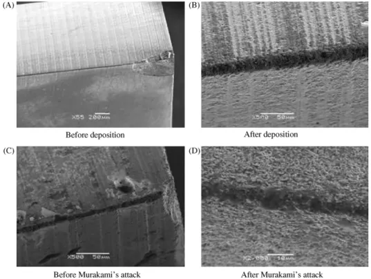
Fig. 4. SEM image of: (A) an uncoated and (B) CrAlN-coated carbide insert’s edge; (C) an unattacked and (D) Murakami’s attacked carbide insert’s edge.
3. Results and discussion
3.1. Physico-chemical characterization of CrAlN coatings 3.1.1. Morphology by SEM
The condition of the edges of the carbide tooling provided by LEITZ was observed. Most of them were already damaged espe-cially at the edges’ corner as shown inFig. 4A. It is obvious that the coating “follows” the roughness of the carbide substrate. In fact, we can still observe the grinding marks after deposition. On the cutting edge, the coatings made in two steps (clear-ance face and then rake face), are well superposed (Fig. 4B). As a consequence, the radius of the edge did not increase too much.
The influence of Murakami’s attack is observed inFig. 4C–D: the WC grains are clearly visible after attack, where the Co was dissolved, particularly near the cutting edge. This attests to the efficiency of this attack.
3.1.2. Composition’s analysis by EDS
According to the EDS analysis, we obtained a constant atomic
composition of 38% of N2, 25% of Al, 25% of Cr and 10%
of O2as shown inFig. 5above 15% of nitrogen in the plasma
during the CrAlN layers deposition. The other deposition
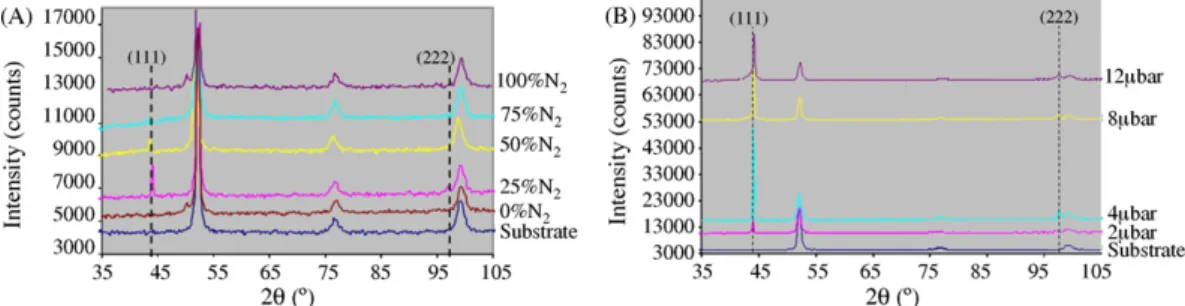
Fig. 6. XRD patterns of CrAlN coatings as a function of: (A) the nitrogen content in the plasma; (B) the working pressure.
eters (working pressure, deposition time, target voltage) had no influence on the coatings’ composition.
3.1.3. Analyses by XRD
The XRD analyses were made on ground steel samples which presented a roughness similar to the one of the carbide inserts. This choice was justified by a previous study in which we observed the same structure of the coatings on steel and carbide substrates[6].
First, we studied the influence of the nitrogen content in the plasma: we observe a minor diffraction peak at 44◦on the XRD patterns ofFig. 6A except for the coatings obtained with 25 and 50% of N2. In the case of the layer obtained with 25% of N2
we have an intense and thin peak at 44◦and a minor one at 98◦ not detected for the other nitrogen contents, which means that we have a well crytallized phase (CrN in an AlN matrix? AlN in a CrN matrix? Or a ternary, a quaternary system such as pure CrAlN or CrAlNO because of the presence of 10% of oxygen? Some complementary analyses (EBSD, XPS, SIMS in progress) are necessary to define the type of phase in presence. Above 25% of N2, the diffraction peaks are smaller and broader. This could
be explained by the fact that higher nitrogen content interferes in the sputtering process and is negative for a good crystallinity. As a conclusion, to obtain well crystallized coatings, we have to work with nitrogen content around 25%.
We verified then the influence of the working pressure (Fig. 6B): only the intensity of the diffraction peaks at 44◦and 98◦varied. It seems that the optimal working pressure is 4bar. When the pressure increases, there are a lot of species in the plasma and so the growth of the layers is disturbed because of the decrease of their rate and energy. Below 4bar, contrarily, there are not enough species and the sputtering rate is decreased as well as the species energy necessary to obtain a well crystallized coating. In these cases, the layers are amorphous.
We also verified the influence of the thickness of the layers: as expected, it was obvious that thicker the layer was, the higher the intensity of the diffraction peak was. All the layers were well crystallized.
Finally, the influence of the target voltage was studied (Fig. 7): the optimal voltage is the highest one. Indeed, we observed that when the target voltage increases, the intensity of the diffraction peaks at 44◦and 98◦increases and the layers are more crystallized. When we work at lower voltage (−300 V), the layers are amorphous. The optimal target voltage is−900 V in our case.
Fig. 7. XRD patterns of CrAlN coatings as a function of the target voltage. 3.2. Mechanical characterizations of CrAlN coatings 3.2.1. Stress and thickness
The stresses were determined by profilometry using Stoney’s
equation[6]and Newton’s rings methods. It is worthy of note
that only the method by profilometry permits to determine if the stress is in tension or compression. We applied the same sign to the stresses obtained by both methods.
We can observe inFig. 8that we obtained a similar behaviour with both methods: a curve presenting a different optimum
(−4 GPa in the case of profilometry and −12 GPa in the case
of Newton’s rings method). Nevertheless, these results permit to determine an optimal time of deposition to get coatings with the lower stresses.
Below 40 min of deposition (layers 400 nm thick), the stresses are too high. As we are looking for a proper adhesion of the lay-ers on cutting tools, we are also looking for the smallest stresses that means those obtained above 60 min (layers > 600 nm thick).
Nouveau[6]obtained similar results for PVD CrN layers
com-pared with TiN, c-BN, etc. and explained this behaviour in previous studies[6–8].
Fig. 9. Examples of damages after scratch-tests on CrAlN layers obtained in different deposition conditions. 3.2.2. Adhesion
The adhesion of the layers was studied by scratch-tests, SEM observations of the damages and calculation of the critical load
Lc2. For all samples, four scratches were realized. Different kind
of damages were observed: small scratches into the track (1), delamination at the side of the track (2), delamination into the
track (3), a beginning of a transversal scratch (4) and a transversal scratch, perpendicularly to the scratch direction (5). Some of these damages are represented inFig. 9.
We observe in Fig. 10A that according to scratch-test, the most adherent layers are obtained for medium or low target volt-ages, which is not in accordance with the XRD results. We should
Table 2
Hardness and Young’s modulus of CrAlN coatings Working pressure
(bar)
Deposition time Target voltage (V) N2content in the plasma (%)
Presputtering time (min)
Hardness (GPa) Young’s modulus E (GPa) 4 90 700 35 5 19.7 270 17.5 22.7 365 900 35 21.4 307 17.5 23.5 402 8 25 8.2 153 12 6.4 121 4 20.3 283 30 26.7 380 60 20.2 350 10 5 25.8 315 180 25 18.35 370
therefore find a compromise to get a well crystallized, hard and also adherent coatings. Besides, as in XRD, we see that the adhe-sion is better for lower working pressure (Fig. 10B). Indeed, for a high working pressure, the load needed to remove the coating from the substrate is almost zero which means that it is not at all adherent.
As the nitrogen content is concerned (Fig. 10C), we can con-clude that higher it is, the better the adhesion of the layers is. Theoretically, we should work with the highest nitrogen content but according to the XRD and other results, good properties are obtained for around 25% of nitrogen, which content permits to get reasonable adherent and well crystallized layers.
3.2.3. Nanoindentation
The results are summarized inTable 2. We observe the influ-ence of the working pressure, the nitrogen content and the target voltage. In fact, the lower the working pressure is, the higher the hardness and the Young’s modulus of the layers are. These results are in accordance with the previous ones: working at low working pressure seems to be optimal. Nevertheless, we cannot work at 2bar because of an unstable RF discharge, that is why 4bar seems to be the optimal working pressure to obtain hard coatings with a reasonable Young’s modulus.
Concerning the nitrogen content, it has a lower influence in comparison to the working pressure, on the hardness of the coat-ings. But it permits to improve it when it decreases to 10–20%. The improvement of the Young’s modulus is obtained for a nitrogen content of 17.5% which is the same as the hardness.
These results tend to confirm the previous ones obtained by XRD where we determined an optimal nitrogen content around 25%: it seems now, that 17.5% of nitrogen is the optimal nitrogen content in the plasma.
The last parameter studied was the target voltage: whatever the deposition conditions, working at high target voltage
(espe-cially −900 V) permitted to obtain the highest hardness and
Young’s modulus. These results confirm the previous ones con-cerning the optimal target voltage to get coatings with good mechanical properties.
As a conclusion, the results obtained by nanoindentation con-firm and complete the XRD analyses: when the layers are well crystallized, they are also hard. The optimal deposition
condi-tions to obtain well crystallized and hard coatings are a working pressure of 4bar, a nitrogen content of 17.5%–25% and a target
voltage of−900 V.
3.3. Application in routing of MDF
First, we tested carbide inserts only CrAlN-coated to verify the efficiency of the layers in routing of MDF. Secondly, we tested the same carbide inserts but before the CrAlN deposition, they were attacked by Murakami’s agent. Then, we studied the efficiency of this pre-treatment of the carbide on the coatings’ adhesion in the same cutting conditions.
3.3.1. Routing of MDF with CrAlN-coated carbide inserts
During this study, we applied the previous determined
opti-mized deposition conditions (4bar, 90 min, −900 V) but we
also wanted to verify the influence of the nitrogen content on the abrasive wear resistance of the coatings in routing. The routing of MDF, a very abrasive composite, was then perfectly adapted. We tested four different tools: an unmodified tool tested only
on one edge, a CrAlN-coated tool with 10% of N2tested twice
(on its both edges), a CrAlN-coated tool with 25% of N2tested
twice (on its both edges) and a CrAlN-coated tool with 35% of N2tested only on one edge.
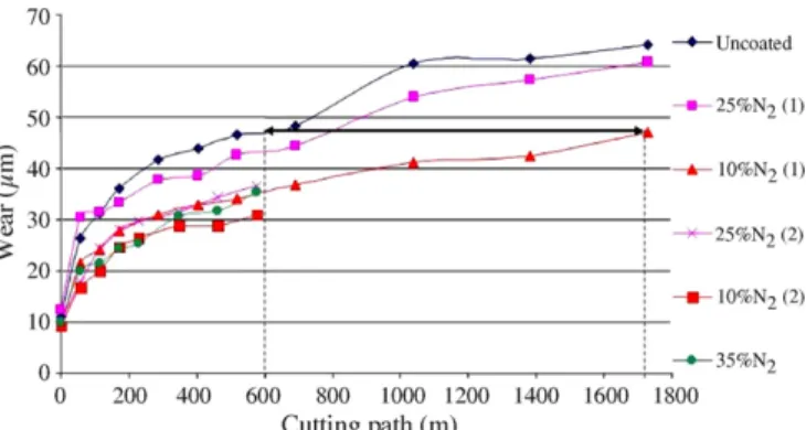
The results are summarized inFig. 11. First, we can notice that the coated tools perform better than the unmodified one. We
Fig. 11. Wear of the cutting edge vs. the cutting path in routing of MDF with CrAlN-coated carbide tools.
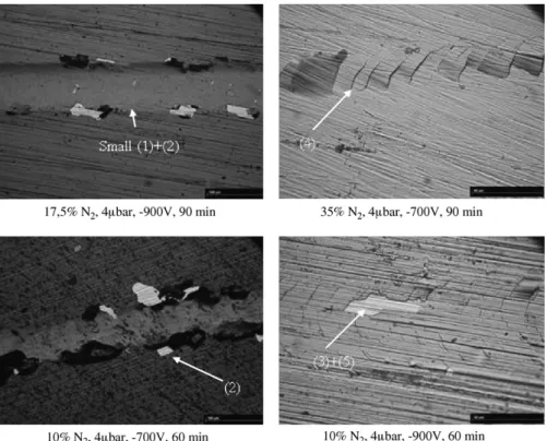
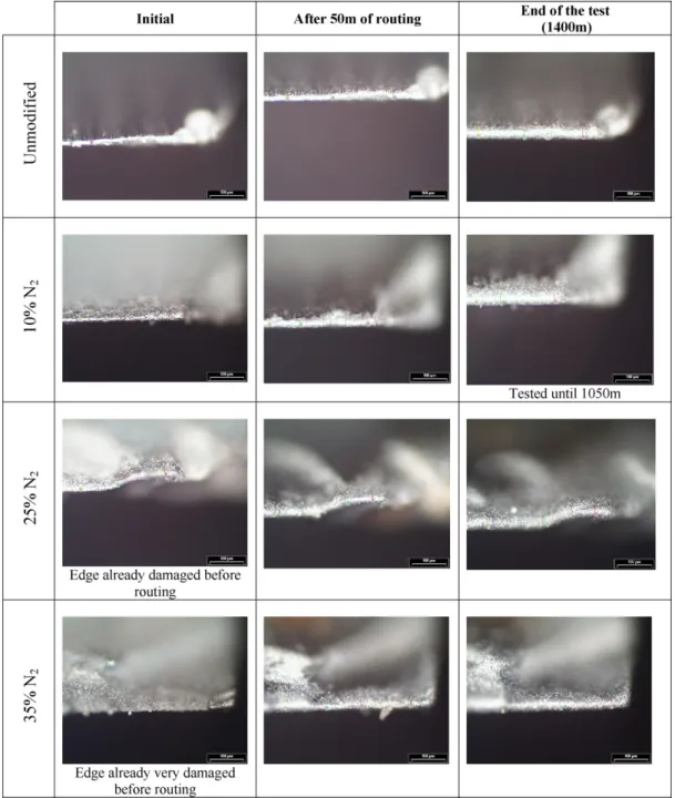
Fig. 12. Optical observations of the cutting edges during routing of MDF (magnification×20) with CrAlN-coated tools.
also see the importance of the lapping (first 150 m of machining): on the one hand, if a tool performed well during this period, it will have good results at the end of the test. On the other hand, like the first test with the carbide coated with 25% of N2, the tool
will not be efficient during the routing process. But as we can see onFig. 11, the best tool is the one coated with 10% of N2
which permitted to machine 2.5 times more than the unmodified tool, for equal wear.
The first edge of the tool coated with 25% of N2presented
a bad surface state observed by SEM which can explain its bad performances.
Another parameter to be studied is the shape of the different curves: during the lapping period and after, the coated tools
always present lower shape than the unmodified one (except for the first edge of the tool coated with 25% of N2).
Besides, we observed by optical microscopy the cutting edges to verify the adhesion of the coatings during the routing process (Fig. 12). We only observed the rake face because this face is the only one in contact with the veneer during the routing pro-cess which means that it is the more stressed during the wood
machining. InFig. 12 we note that the more adherent coating
seems to be the one obtained with 25% of N2in the plasma.
Besides, the one obtained with 10% of N2in the plasma is the
less adherent while it is the most efficient in wear resistance. This probably means that after 1700 m of routing, this tool must lose its efficiency. These results could also be explained by the
Fig. 13. Wear of the cutting edge vs. the cutting path in routing of MDF with Murakami’s attacked and CrAlN-coated carbide tools.
highest hardness so a highest fragility of this coating which were verified in scratch-test (Fig. 10C).
As a conclusion, according to these results we should employ coatings with around 20% of nitrogen for routing instead of 10 or more than 25%.
3.3.2. Routing of MDF with Murakami’s attacked and CrAlN-coated carbide inserts
Secondly, we tested CrAlN-coated tools previously attacked with Murakami’s agent in routing of MDF. We also verified the influence of the nitrogen content while the other parameters were fixed. The results are shown inFig. 13. As we can see they are not at all positive: during the lapping period or even after, the pre-treated tools behaved worse than the unmodified one. It seems
clear that Murakami’s attack weakened the carbides: maybe a 5 min attack was too long, which resulted in a too deep cobalt dissolution and to the removal of the WC grains at the tools surfaces? SEM observations showed before machining that the attack was especially concentrated near the cutting edge which could explain the fast degradation of the tools. After removal of the surface attacked of the cutting edges, the tools behaved like the unmodified one, as if they had not been treated at all. The degradation seems to be higher in the case of the tool coated
with 35% of N2in the plasma which always behave worse than
the other ones.
As we observe inFig. 14, the fast wear of the pre-treated tools came from the WC grains removal: we see on all optical images that the coating is still present at the end of the test (dark zone) even on very damaged cutting edges.
4. Conclusions
During this study, we optimized the deposition conditions by RF magnetron sputtering of CrAlN coatings in view to apply them on carbide inserts for routing of MDF. The optimal physico-chemical and mechanical properties were obtained for a working pressure of 4bar, a target voltage of −900 V, a depo-sition time of 90 min (around 1.5m) and a nitrogen content in the plasma of around 20%.
In these conditions, we obtained coatings with hardness of around 20 GPa and adherent on carbide tools. The coatings are also low stressed and permit to machine up till 2.5 times more than unmodified ones after 1700 m of routing.
Nevertheless, Murakami’s agent attack failed even if the coat-ings were efficient which means that this is perhaps not a solution to improve the adhesion of nitride coatings on carbide inserts. An optimization of the attack is necessary and is in progress.
Acknowledgements
We wish to thank the Regional Council of Burgundy for its financial support of the study. We also thank ISOROY France who provided us MDF panels for routing. Finally we wish to thank all colleagues (from Dijon, Angers, Besanc¸on) who helped us for the characterizations of our layers.
References
[1] M. Van Stappen, M. Kerkhofs, L.M. Stals, C. Quaeyhaegens, State of the art for the industrial use of ceramic PVD coatings, Surf. Coat. Technol. 74–75 (1995) 629–633.
[2] C. Nouveau, M.-A. Djouadi, R. Marchal, M. Lambertin, Applications de revˆetements durs (CrxNy) obtenus par m´ethodes P.V.D. `a l’usinage du bois:
Applications of hard coatings (CrxNy) obtained by P.V.D. methods in wood
machining, M´eca. Indus. 3 (2002) 333–342.
[3] C. Labidi, R. Collet, C. Nouveau, P. Beer, S. Nicosia, M.-A. Djouadi, Surface treatments of tools used in industrial wood machining, Surf. Coat. Technol. 200 (1–4) (2005) 118–122.
[4] T. Morita, J. Sheikh-Ahmad, K. Banshoya, T. Tsutsumoto, Y. Murase, Forest Products J. 50 (1) (2000) 67–73.
[5] C. Labidi, R. Collet, C. Nouveau, M.-A. Djouadi, S. Nicosia, P. Beer, Behaviour of modified canter and peeling knives in primary wood transfor-mation, in: Proceedings of the Second International Symposium on Wood Machining, July 5–7, 2004, pp. 475–480.
[6] C. Nouveau, Etude de revˆetements durs (CrxNy) obtenus par m´ethodes PVD:
r´ealisation et caract´erisations, applications `a l’usinage du bois, Ph.D. (n◦ 21-2001), CER ENSAM Cluny France.
[7] C. Nouveau, M.-A. Djouadi, O. Banakh, R. Sanjin´es, F. L´evy, Stress and structure profiles for chromium nitride coatings deposited by r.f. magnetron sputtering, Thin Solid Films 398–399 (2001) 490–495.
[8] M.-A. Djouadi, C. Nouveau, O. Banakh, R. Sanjin´es, F. L´evy, G. Nouet, Stress profiles and thermal stability of CrxNyfilms deposited by magnetron